EP1157751B1 - Elektrodynamischer Wandler für Unterwasserakustik - Google Patents
Elektrodynamischer Wandler für Unterwasserakustik Download PDFInfo
- Publication number
- EP1157751B1 EP1157751B1 EP01401347A EP01401347A EP1157751B1 EP 1157751 B1 EP1157751 B1 EP 1157751B1 EP 01401347 A EP01401347 A EP 01401347A EP 01401347 A EP01401347 A EP 01401347A EP 1157751 B1 EP1157751 B1 EP 1157751B1
- Authority
- EP
- European Patent Office
- Prior art keywords
- transducer
- air
- pole pieces
- dome
- winding
- Prior art date
- Legal status (The legal status is an assumption and is not a legal conclusion. Google has not performed a legal analysis and makes no representation as to the accuracy of the status listed.)
- Expired - Lifetime
Links
- 230000005520 electrodynamics Effects 0.000 title claims description 7
- 239000012528 membrane Substances 0.000 claims description 10
- 238000004880 explosion Methods 0.000 claims description 7
- 230000035939 shock Effects 0.000 claims description 6
- 238000004804 winding Methods 0.000 claims description 6
- 229910052782 aluminium Inorganic materials 0.000 claims description 3
- XAGFODPZIPBFFR-UHFFFAOYSA-N aluminium Chemical compound [Al] XAGFODPZIPBFFR-UHFFFAOYSA-N 0.000 claims description 3
- 239000004411 aluminium Substances 0.000 claims 1
- 238000001816 cooling Methods 0.000 description 3
- 230000006866 deterioration Effects 0.000 description 3
- 241000251468 Actinopterygii Species 0.000 description 2
- 230000009471 action Effects 0.000 description 2
- 238000004891 communication Methods 0.000 description 2
- 230000000694 effects Effects 0.000 description 2
- 239000012530 fluid Substances 0.000 description 2
- 230000017525 heat dissipation Effects 0.000 description 2
- 238000010438 heat treatment Methods 0.000 description 2
- 239000000463 material Substances 0.000 description 2
- 229910052751 metal Inorganic materials 0.000 description 2
- 239000002184 metal Substances 0.000 description 2
- 238000000034 method Methods 0.000 description 2
- 239000013535 sea water Substances 0.000 description 2
- 238000007789 sealing Methods 0.000 description 2
- 235000001674 Agaricus brunnescens Nutrition 0.000 description 1
- 229920000049 Carbon (fiber) Polymers 0.000 description 1
- 238000004026 adhesive bonding Methods 0.000 description 1
- 230000016571 aggressive behavior Effects 0.000 description 1
- 230000002238 attenuated effect Effects 0.000 description 1
- 238000005452 bending Methods 0.000 description 1
- 230000005540 biological transmission Effects 0.000 description 1
- 239000004917 carbon fiber Substances 0.000 description 1
- 230000015556 catabolic process Effects 0.000 description 1
- 239000004020 conductor Substances 0.000 description 1
- 238000006731 degradation reaction Methods 0.000 description 1
- 238000010586 diagram Methods 0.000 description 1
- 238000006073 displacement reaction Methods 0.000 description 1
- 239000004744 fabric Substances 0.000 description 1
- 229940020445 flector Drugs 0.000 description 1
- 230000004907 flux Effects 0.000 description 1
- 239000006260 foam Substances 0.000 description 1
- 230000002706 hydrostatic effect Effects 0.000 description 1
- 238000007654 immersion Methods 0.000 description 1
- 230000003993 interaction Effects 0.000 description 1
- 230000002427 irreversible effect Effects 0.000 description 1
- 238000010030 laminating Methods 0.000 description 1
- 238000003754 machining Methods 0.000 description 1
- 238000004519 manufacturing process Methods 0.000 description 1
- 239000011159 matrix material Substances 0.000 description 1
- VNWKTOKETHGBQD-UHFFFAOYSA-N methane Chemical compound C VNWKTOKETHGBQD-UHFFFAOYSA-N 0.000 description 1
- 238000003801 milling Methods 0.000 description 1
- 230000004048 modification Effects 0.000 description 1
- 238000012986 modification Methods 0.000 description 1
- 230000008439 repair process Effects 0.000 description 1
- 239000011347 resin Substances 0.000 description 1
- 229920005989 resin Polymers 0.000 description 1
- 238000005096 rolling process Methods 0.000 description 1
- 239000007787 solid Substances 0.000 description 1
- XLYOFNOQVPJJNP-UHFFFAOYSA-N water Substances O XLYOFNOQVPJJNP-UHFFFAOYSA-N 0.000 description 1
Images

Classifications
-
- G—PHYSICS
- G10—MUSICAL INSTRUMENTS; ACOUSTICS
- G10K—SOUND-PRODUCING DEVICES; METHODS OR DEVICES FOR PROTECTING AGAINST, OR FOR DAMPING, NOISE OR OTHER ACOUSTIC WAVES IN GENERAL; ACOUSTICS NOT OTHERWISE PROVIDED FOR
- G10K11/00—Methods or devices for transmitting, conducting or directing sound in general; Methods or devices for protecting against, or for damping, noise or other acoustic waves in general
- G10K11/004—Mounting transducers, e.g. provided with mechanical moving or orienting device
- G10K11/006—Transducer mounting in underwater equipment, e.g. sonobuoys
-
- B—PERFORMING OPERATIONS; TRANSPORTING
- B06—GENERATING OR TRANSMITTING MECHANICAL VIBRATIONS IN GENERAL
- B06B—METHODS OR APPARATUS FOR GENERATING OR TRANSMITTING MECHANICAL VIBRATIONS OF INFRASONIC, SONIC, OR ULTRASONIC FREQUENCY, e.g. FOR PERFORMING MECHANICAL WORK IN GENERAL
- B06B1/00—Methods or apparatus for generating mechanical vibrations of infrasonic, sonic, or ultrasonic frequency
- B06B1/02—Methods or apparatus for generating mechanical vibrations of infrasonic, sonic, or ultrasonic frequency making use of electrical energy
- B06B1/04—Methods or apparatus for generating mechanical vibrations of infrasonic, sonic, or ultrasonic frequency making use of electrical energy operating with electromagnetism
- B06B1/045—Methods or apparatus for generating mechanical vibrations of infrasonic, sonic, or ultrasonic frequency making use of electrical energy operating with electromagnetism using vibrating magnet, armature or coil system
Definitions
- the present invention relates to transducers of the electrodynamic type which make it possible to emit acoustic waves in the sea, more particularly sound waves. These transducers are particularly useful in sonar technique.
- Underwater acoustics are used for towed fish with electronic devices and various transducers that can operate in transmission, reception and possibly in both modes.
- transducers of the electrodynamic type which comprise a flag driven by a voice coil located in an air gap.
- This transducer according to the prior art, represented on the Figures 1 and 2 appended, comprises a body formed of a base 101 on which is fitted a shirt 102 surmounted by a cup 103. These different parts fit into each other so as to define cylindrical cavities of revolution around the l axis of the transducer, in which are inserted the other parts forming the transducer.
- a first cylindrical cavity delimited between the base and the liner makes it possible to maintain a magnetic circuit formed of first and second pole pieces 104 and 105 in the form of rings centered on the axis of the transducer.
- the first pole piece 104 is L-shaped with the inner branch of the L that overflows inside the central chamber of the transducer.
- the second pole piece 105 is in the form of a flat washer. Both are kept separated by a set of magnets 106 on which they are tightened by the adjustment of the liner 102 in the base 101. In this way, a magnetic circuit is obtained which is only interrupted by a thin air gap 107 presenting the shape of a cylinder centered on the axis of the transducer and coming flush with the inner lateral surface of the cup 103.
- the central space of the transducer body forms a second cylindrical cavity in which a mushroom-shaped core 108 is embedded by its central rod in the central circular opening of the pole piece 104.
- the moving element of the transducer is formed by a hollow piece 109 having the shape of a dome covering a cylindrical portion which engages in the air gap 107. So that this piece is at the same time very solid, very light and very rigid, it is for example formed by a carbon fiber fabric embedded in a resin matrix.
- the upper surface of the dome 109 is covered with a part 110 whose upper surface is substantially flat and which forms the radiative flag of the transducer. It is performed to be itself very light, for example syntactic foam.
- Crown 110 therefore behaves like a piston whose lateral outer surface is cylindrical. This piston slides in a cylinder formed by the lateral inner surface of the cup 103, itself substantially cylindrical. These two parts, and more particularly the roof 110, are made to have an extremely small adjustment play, of the order of 0.2 mm for example. A mechanical filter is thus formed which slows down the propagation of the shock wave that may come from an eventual external explosion, by rolling in this gap the fluid in which the flag is bathed.
- the upper part of the central space of the transducer body is filled with a fluid, an oil for example, adapted to both this protection and the propagation of acoustic waves.
- a fluid an oil for example, adapted to both this protection and the propagation of acoustic waves.
- the space 113 is closed at its upper part by a membrane 112, which is fixed on the periphery of the cup 103.
- the lower part of the central space, opposite the part where the oil is, is filled with air.
- another sealing membrane 115 made of rubber for example, which is much more flexible than the membrane 112 and which is a part fixed on the outer side wall of the roof 110 and secondly on the inner side wall of the cup 103. This attachment is made by pinching between the cup 103 and the shirt 102.
- the external lateral surface of the flag is machined at this level to present a withdrawal relative to the nozzle 111, which has the reduced clearance described above, and form a free space for the membrane 115.
- this assembly is stiffened by using a set of radial ribs 116 which are distributed on the inner periphery of the dome 109 and meet in a star below the lower part of the mushroom rod forming the core 108. These ribs slide in grooves 117 formed in the core 108 and in the first pole piece 104. These grooves are relatively wide at the core and are narrower at the pole piece to minimize the loss of magnetic flux, which can be reduced to a very low value. low of a few percent.
- An axis 118 joins the center of the upper part of the dome 109 in the center of the star formed by the reunion of the ribs 116, below the lower face of the core 108.
- This axis makes it possible at the same time to stiffen the assembly and to ensure its vertical centering with respect to the axis of the transducer.
- the axis is fixed by its lower part in the center of a flat spring 119 itself fixed circumferentially in the lower part of the base 101.
- This spring of the type known as "flector Is formed of a flexible and resilient washer carrying circumferential openings for allowing air to pass freely in the lower part of the central space of the transducer, between the two parts delimited by the plane of this spring. This spring ensures not only the centering, but it avoids the rotational movements of the moving element that would rub the ribs against the walls of the grooves in which they slide.
- the driving action that makes it possible to move the dome / horn assembly along the axis of the transducer, to emit the acoustic waves, is obtained by the interaction between the magnetic field which circulates between the pole pieces and that delivered by a coil 120 wound on the lateral flanks of the lower cylindrical portion of the dome 109.
- This coil is thus immersed in the air gap existing between the two pole pieces, which realizes the conventional diagram of an electrodynamic transducer, this coil is powered by means not shown in the figure and which are known in the art.
- the ribs 116 also serve as a heat sink over the entire height of the coil 120, to dissipate the heat generated at this level by directing it to the other parts of the transducer.
- the internal portion 114 delimited by the dome 109, the base 101 whose bottom is closed, the jacket 102 and the sealing membrane 115 is filled with air to allow the movement of the moving assembly, as has been seen above.
- the mobile assembly When the transducer is immersed, under the effect of the hydrostatic pressure, the mobile assembly is sinking towards the bottom of the base 101 by compressing the spring 119 and the volume of air included in this portion 114.
- This movement of course, to modify the electroacoustic characteristics of the transducer, in particular by modifying the respective positions of the coil and the pole pieces,
- a compensation tank, or air chamber, 121 formed of a flexible bag, of rubber for example, subjected to the pressure of the marine environment and communicating with the part 114 by 122.
- this inner tube is of toroidal shape and is located in another internal cylindrical cavity 123 which is delimited to the interior of the transducer by the walls of the jacket 102 and the cup 103. This cavity is itself toroidal and closed and surrounds the location of the flag 110.
- openings 124 which allow the seawater to enter the cavity 123 and to compress the air chamber.
- the inner tube is protected against mechanical external aggression by the walls of the cavity where it is located.
- the diameter of the openings 124 is provided so that the shock waves from an eventual external explosion is attenuated through these openings, so that they do not present any danger of overpressure at the level of the inner tube.
- These openings being round, their diameter may be greater than the thickness of the nozzle 111.
- Such a transducer works perfectly, and resists for example the explosion of a ton of TNT located 30m from it.
- the large current which then flows in the coil 120 causes a strong local heating which can not be dissipated properly by the means provided to date, in particular by the fins 116.
- an electrodynamic transducer for underwater acoustics of the type comprising a body provided with pole pieces defining an air gap, a moving element provided with an extended dome by a cylinder supporting a sliding winding in this air gap, a flexible membrane ensuring the seal between the mobile equipment and the body by determining an inner part filled with air, and a flag overlying said dome and sliding in said body forming with it is a nozzle whose play value is set so as to protect said membrane against shock waves from explosions external to the transducer by laminating these shock waves in said nozzle, mainly characterized in that one said pole pieces is provided with at least one opening for the circulation of air inside the inner part for effectively cooling said winding.
- it further comprises a conductive mass of the heat located between said pole pieces for draining the heat generated by the winding towards the outside of the transducer.
- it further comprises a set of magnets placed between the pole pieces, characterized in that it further comprises a set of heat conductive masses interposed between the magnets.
- said heat-conducting masses are made of aluminum.
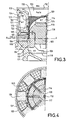
- the invention therefore proposes to eliminate the confinement of the air in this part 130 where the lower part of the coil 120 is immersed by forming holes 131 in the magnetic circuit 104.
- These holes which are in this embodiment substantially vertical, therefore put in communication the portion 130 of the cavity 114 with the portion 126 of the same cavity, located at the bottom of the transducer under the core 108.
- the communication additional created thus between the portion 125 of the cavity 114, located above the core 108 and this portion 126, allows a flow of air.
- the latter having heated in contact with the coil 120 comes up in the part 125, cools by contact with the different massive parts of the transducer, then returns to the portion 126 of the cavity 114 down through the various orifices located in the central part of the transducer.
- the invention proposes, in the exemplary embodiment shown on the Figures 3 and 4 , machining the lower portion of the housing 101, inside thereof at the portion 126 of the cavity 114, milling the interior thereof so as to disengage a circular shoulder 132 so that the holes 131 may themselves be machined vertically while opening into the portion 126 of the cavity 114.
- the invention proposes, to improve the transfer of heat between the inside of the transducer, more particularly since the volume of air flowing at the portion 130 of the cavity 114, to place between the magnets 106 metal masses 135 which form thermal drains between the inside of the transducer and the external environment, by the intermediate of the shirt 102.
- These metal masses are machined to provide a maximum thermal path to the heat released by occupying as much space as possible between the magnets. They are made of a material that is as much as possible heat conductor while remaining light enough not to weigh down the mass of the transducer. Among the most suitable materials for this use include aluminum. They are held, for example by gluing, on the pole piece 104, or possibly by pinching between the pole pieces 104 and 105 in the same manner as the magnets 106.
- a transducer made in this way can withstand a current that can be at least 4 times higher than the admissible current in a transducer according to the prior art, without it being necessary to make any modification to the rest of the transducer, in particular to the coil, and obtaining identical performance without any degradation.
Landscapes
- Physics & Mathematics (AREA)
- Engineering & Computer Science (AREA)
- Acoustics & Sound (AREA)
- Multimedia (AREA)
- Electromagnetism (AREA)
- Mechanical Engineering (AREA)
- Audible-Bandwidth Dynamoelectric Transducers Other Than Pickups (AREA)
Claims (4)
- Elektrodynamischer Wandler für Unterwasser-Akustik, von der Art mit einem Körper (101-103), der mit Polteilen (104, 105) versehen ist, die einen Luftspalt (107) definieren, mit einem beweglichen Organ, das mit einer Kuppel (109) versehen ist, die sich in einem eine Wicklung (120) tragenden Zylinder fortsetzt, der in diesem Luftspalt gleitet, mit einer flexiblen Membran (115), die für die Dichtheit zwischen dem beweglichen Organ und dem Körper sorgt, indem sie einen mit Luft gefüllten inneren Bereich (114) bestimmt, und mit einem Schalltrichter (110), der die Kuppel (109) überragt und in dem Körper gleitet, indem er mit diesem eine Düse (111) bildet, deren Wert für ihr Spiel so festgelegt wird, dass er es gestattet, die Membran vor den Stoßwellen zu schützen, die von Explosionen außerhalb des Wandlers kommen, indem diese Stoßwellen in der Düse gedrosselt werden, dadurch gekennzeichnet, dass eines der Polteile (104) mit mindestens einer Öffnung (131) versehen ist, die die Luftzirkulation im Inneren des inneren Bereichs (114) ermöglicht, um die Wicklung wirksam zu kühlen.
- Wandler nach Anspruch 1, dadurch gekennzeichnet, dass er außerdem mindestens eine wärmeleitende Masse (135) aufweist, die sich zwischen den Polteilen (104, 105) befindet, um die von der Wicklung (120) abgegebene Wärme nach außerhalb des Wandlers abzuziehen.
- Wandler nach Anspruch 2, der einen Satz von Magneten (106) aufweist, die zwischen den Polteilen (104-105) angeordnet sind, dadurch gekennzeichnet, dass er außerdem einen Satz von wärmeleitenden Massen (135) aufweist, die zwischen die Magnete eingeschoben sind.
- Wandler nach einem der Ansprüche 2 und 3, dadurch gekennzeichnet, dass die wärmeleitenden Massen (135) aus Aluminium hergestellt sind.
Applications Claiming Priority (2)
| Application Number | Priority Date | Filing Date | Title |
|---|---|---|---|
| FR0006766A FR2809580B1 (fr) | 2000-05-26 | 2000-05-26 | Transducteur electrodynamique pour acoustique sous-marine |
| FR0006766 | 2000-05-26 |
Publications (2)
| Publication Number | Publication Date |
|---|---|
| EP1157751A1 EP1157751A1 (de) | 2001-11-28 |
| EP1157751B1 true EP1157751B1 (de) | 2009-05-06 |
Family
ID=8850663
Family Applications (1)
| Application Number | Title | Priority Date | Filing Date |
|---|---|---|---|
| EP01401347A Expired - Lifetime EP1157751B1 (de) | 2000-05-26 | 2001-05-22 | Elektrodynamischer Wandler für Unterwasserakustik |
Country Status (4)
| Country | Link |
|---|---|
| US (1) | US6515940B2 (de) |
| EP (1) | EP1157751B1 (de) |
| DE (1) | DE60138588D1 (de) |
| FR (1) | FR2809580B1 (de) |
Families Citing this family (5)
| Publication number | Priority date | Publication date | Assignee | Title |
|---|---|---|---|---|
| FR2809580B1 (fr) * | 2000-05-26 | 2002-08-30 | Thomson Marconi Sonar Sas | Transducteur electrodynamique pour acoustique sous-marine |
| US7408842B2 (en) * | 2006-03-30 | 2008-08-05 | Materials Sciences Corporation | Sonar dome |
| FR3015785B1 (fr) * | 2013-12-20 | 2015-12-25 | Thales Sa | Antenne omnidirectionnelle compacte pour sonar trempe |
| CN108301820B (zh) * | 2018-05-02 | 2023-04-21 | 重庆科技学院 | 一种地层钻孔内声波探测装置及其探测方法 |
| CN119565895B (zh) * | 2024-12-03 | 2026-01-06 | 哈尔滨工程大学 | 一种圆周辐射的多元振子高效电动式换能器 |
Family Cites Families (21)
| Publication number | Priority date | Publication date | Assignee | Title |
|---|---|---|---|---|
| BE757591A (fr) | 1969-11-25 | 1971-03-16 | Thomson Csf | Perfectionnements aux domes de systemes sonars et procede de leur fabrication |
| FR2290812A1 (fr) | 1974-11-08 | 1976-06-04 | Thomson Csf | Transducteur electroacoustique pour immersion profonde |
| GB1518138A (en) | 1974-12-17 | 1978-07-19 | Thomson Csf | Cooling device for components which dissipate large amounts of heat |
| FR2431419A1 (fr) | 1978-07-18 | 1980-02-15 | Thomson Csf | Bouee aeroportee largable |
| FR2450193A1 (fr) | 1979-02-27 | 1980-09-26 | Thomson Csf | Bouee aeroportee largable a declenchement inertiel |
| FR2464179A2 (fr) | 1979-08-28 | 1981-03-06 | Thomson Csf | Bouee aeroportee largable |
| US4736350A (en) * | 1986-02-24 | 1988-04-05 | Fred M. Dellorfano, Jr. | Electromagnetic transducers for underwater low-frequency high-power use |
| US5062089A (en) * | 1987-04-17 | 1991-10-29 | Argotec Inc. | Sonar projector with liquid mass loading for operation at lower frequency |
| FR2622333B1 (fr) | 1987-10-27 | 1990-01-26 | Thomson Csf | Revetement anechoique pour ondes acoustiques |
| FR2640455B1 (fr) | 1988-07-08 | 1991-05-17 | Thomson Csf | Transducteur electroacoustique, utilisable notamment comme source d'ondes acoustiques pour les applications sous-marines |
| FR2639786B1 (fr) | 1988-11-04 | 1991-07-26 | Thomson Csf | Transducteur flextenseur |
| GB2231153B (en) * | 1989-04-29 | 1992-11-18 | Ferranti Int Signal | Electromechanical transducer |
| FR2656971B1 (fr) | 1990-01-05 | 1992-09-04 | Thomson Csf | Hydrophone basse frequence et antenne sonar comportant de tels hydrophones. |
| FR2662099B1 (fr) * | 1990-05-18 | 1994-08-05 | Mecanique Magnetique Sa | Vibreur basse frequence a grande amplitude. |
| FR2672179B1 (fr) | 1991-01-25 | 1993-04-16 | Thomson Csf | Transducteur acoustique flextenseur pour immersion profonde. |
| FR2725684A1 (fr) | 1994-10-18 | 1996-04-19 | Thomson Csf | Bouee aeroportee largable |
| FR2730894B3 (fr) | 1995-02-21 | 1997-03-14 | Thomson Csf | Procede de fabrication d'une carte electronique a refroidissement par conduction thermique |
| FR2744870B1 (fr) | 1996-02-13 | 1998-03-06 | Thomson Csf | Procede pour controler la navigation d'une antenne acoustique lineaire remorquee, et dispositifs pour la mise en oeuvre d'un tel procede |
| FR2764160B1 (fr) * | 1997-05-27 | 1999-08-27 | Thomson Marconi Sonar Sas | Transducteur electrodynamique pour acoustique sous-marine |
| FR2776161B1 (fr) | 1998-03-10 | 2000-05-26 | Thomson Marconi Sonar Sas | Antenne d'emission acoustique annulaire demontable |
| FR2809580B1 (fr) * | 2000-05-26 | 2002-08-30 | Thomson Marconi Sonar Sas | Transducteur electrodynamique pour acoustique sous-marine |
-
2000
- 2000-05-26 FR FR0006766A patent/FR2809580B1/fr not_active Expired - Lifetime
-
2001
- 2001-05-22 DE DE60138588T patent/DE60138588D1/de not_active Expired - Lifetime
- 2001-05-22 EP EP01401347A patent/EP1157751B1/de not_active Expired - Lifetime
- 2001-05-25 US US09/864,313 patent/US6515940B2/en not_active Expired - Lifetime
Also Published As
| Publication number | Publication date |
|---|---|
| DE60138588D1 (de) | 2009-06-18 |
| FR2809580A1 (fr) | 2001-11-30 |
| EP1157751A1 (de) | 2001-11-28 |
| FR2809580B1 (fr) | 2002-08-30 |
| US6515940B2 (en) | 2003-02-04 |
| US20020034124A1 (en) | 2002-03-21 |
Similar Documents
| Publication | Publication Date | Title |
|---|---|---|
| EP3414756A1 (de) | Akustischer absorber, akustische wand und verfahren zur konstruktion und herstellung | |
| EP1157751B1 (de) | Elektrodynamischer Wandler für Unterwasserakustik | |
| EP2177047B1 (de) | Elektrodynamischer wandler, insbesondere nach art eines lautsprechers mit einer ferrofluid-aufhängung und entsprechende vorrichtungen | |
| EP2908023A1 (de) | Steuerbares hydraulisches schwingungsdämpfendes Lager | |
| EP3677051B1 (de) | Wasserschallgehäuse | |
| CA2101053C (fr) | Transducteur acoustique flextenseur pour immersion profonde | |
| EP0317380A1 (de) | Bekleidung mit niedriger Schallrefektion | |
| EP0881001B1 (de) | Elektrodynamischer Wandler für Unterwasser-Akustik | |
| EP3029351B1 (de) | Steuerbares hydraulisches schwingungsdämpfendes lager | |
| FR2628805A1 (fr) | Structure de montage elastique a remplissage de fluide a elements mobiles et a orifices | |
| FR3054628A1 (fr) | Dispositif antivibratoire hydraulique | |
| FR3054629A1 (fr) | Dispositif antivibratoire hydraulique | |
| EP4674139A1 (de) | Architektur zur montage eines elektrodynamischen trägheitswandlers | |
| EP0600758B1 (de) | Dichtungsvorrichtung für elektro-akustische Motoren | |
| FR2504520A1 (fr) | Materiau formable d'isolation et d'absorption acoustiques et son procede de formage | |
| FR2833450A1 (fr) | Antenne acoustique a grande puissance d'emission | |
| EP2392151B1 (de) | Bewegliches teil und mit einem solchen beweglichen teil ausgestatteter elektrodynamischer wandler | |
| FR2709343A1 (fr) | Bouche d'aération auto-réglable, acoustiquement isolante. | |
| FR2739521A1 (fr) | Transducteur electroacoustique et antenne de sonar equipee d'un tel transducteur | |
| EP2567387A1 (de) | Elektrische anlage mit mehreren vorrichtungen zur unterdrückung des rauschens der wellen aus dem aktiven induktionsteil mit abgesicherter vakuumdichtigkeit | |
| FR2548477A1 (fr) | Moteur electrique immergeable en presence d'appareillages affectes par les bruits transmis par l'eau | |
| EP0313462B1 (de) | Hydraulische Antischwingungslager | |
| FR2720590A1 (fr) | Antenne acoustique passive absorbante. | |
| EP0596763A1 (de) | Verfahren und Wandler zum Aussenden von niederfrequenten akustischen Wellen, welcher in einer Flüssigkeit unbeschränkt eingetaucht ist | |
| WO2012107682A1 (fr) | Dispositif de moteur magnétique de transducteur électrodynamique |
Legal Events
| Date | Code | Title | Description |
|---|---|---|---|
| PUAI | Public reference made under article 153(3) epc to a published international application that has entered the european phase |
Free format text: ORIGINAL CODE: 0009012 |
|
| AK | Designated contracting states |
Kind code of ref document: A1 Designated state(s): BE DE GB IT NL Kind code of ref document: A1 Designated state(s): AT BE CH CY DE DK ES FI FR GB GR IE IT LI LU MC NL PT SE TR |
|
| AX | Request for extension of the european patent |
Free format text: AL;LT;LV;MK;RO;SI |
|
| 17P | Request for examination filed |
Effective date: 20020221 |
|
| AKX | Designation fees paid |
Free format text: BE DE GB IT NL |
|
| GRAP | Despatch of communication of intention to grant a patent |
Free format text: ORIGINAL CODE: EPIDOSNIGR1 |
|
| GRAS | Grant fee paid |
Free format text: ORIGINAL CODE: EPIDOSNIGR3 |
|
| GRAA | (expected) grant |
Free format text: ORIGINAL CODE: 0009210 |
|
| RAP1 | Party data changed (applicant data changed or rights of an application transferred) |
Owner name: THALES UNDERWATER SYSTEMS SAS |
|
| AK | Designated contracting states |
Kind code of ref document: B1 Designated state(s): BE DE GB IT NL |
|
| REG | Reference to a national code |
Ref country code: GB Ref legal event code: FG4D Free format text: NOT ENGLISH |
|
| REF | Corresponds to: |
Ref document number: 60138588 Country of ref document: DE Date of ref document: 20090618 Kind code of ref document: P |
|
| NLV1 | Nl: lapsed or annulled due to failure to fulfill the requirements of art. 29p and 29m of the patents act | ||
| BERE | Be: lapsed |
Owner name: THALES UNDERWATER SYSTEMS SAS Effective date: 20090531 |
|
| PG25 | Lapsed in a contracting state [announced via postgrant information from national office to epo] |
Ref country code: NL Free format text: LAPSE BECAUSE OF FAILURE TO SUBMIT A TRANSLATION OF THE DESCRIPTION OR TO PAY THE FEE WITHIN THE PRESCRIBED TIME-LIMIT Effective date: 20090506 |
|
| PLBE | No opposition filed within time limit |
Free format text: ORIGINAL CODE: 0009261 |
|
| STAA | Information on the status of an ep patent application or granted ep patent |
Free format text: STATUS: NO OPPOSITION FILED WITHIN TIME LIMIT |
|
| 26N | No opposition filed |
Effective date: 20100209 |
|
| PG25 | Lapsed in a contracting state [announced via postgrant information from national office to epo] |
Ref country code: BE Free format text: LAPSE BECAUSE OF NON-PAYMENT OF DUE FEES Effective date: 20090531 |
|
| PG25 | Lapsed in a contracting state [announced via postgrant information from national office to epo] |
Ref country code: IT Free format text: LAPSE BECAUSE OF FAILURE TO SUBMIT A TRANSLATION OF THE DESCRIPTION OR TO PAY THE FEE WITHIN THE PRESCRIBED TIME-LIMIT Effective date: 20090506 |
|
| PGFP | Annual fee paid to national office [announced via postgrant information from national office to epo] |
Ref country code: DE Payment date: 20140515 Year of fee payment: 14 |
|
| REG | Reference to a national code |
Ref country code: DE Ref legal event code: R119 Ref document number: 60138588 Country of ref document: DE |
|
| PG25 | Lapsed in a contracting state [announced via postgrant information from national office to epo] |
Ref country code: DE Free format text: LAPSE BECAUSE OF NON-PAYMENT OF DUE FEES Effective date: 20151201 |
|
| PGFP | Annual fee paid to national office [announced via postgrant information from national office to epo] |
Ref country code: GB Payment date: 20170511 Year of fee payment: 17 |
|
| GBPC | Gb: european patent ceased through non-payment of renewal fee |
Effective date: 20180522 |
|
| PG25 | Lapsed in a contracting state [announced via postgrant information from national office to epo] |
Ref country code: GB Free format text: LAPSE BECAUSE OF NON-PAYMENT OF DUE FEES Effective date: 20180522 |
|
| P01 | Opt-out of the competence of the unified patent court (upc) registered |
Effective date: 20230606 |