EP1156978B1 - Drive for a lifting device - Google Patents
Drive for a lifting device Download PDFInfo
- Publication number
- EP1156978B1 EP1156978B1 EP00916852A EP00916852A EP1156978B1 EP 1156978 B1 EP1156978 B1 EP 1156978B1 EP 00916852 A EP00916852 A EP 00916852A EP 00916852 A EP00916852 A EP 00916852A EP 1156978 B1 EP1156978 B1 EP 1156978B1
- Authority
- EP
- European Patent Office
- Prior art keywords
- drive
- brake
- reduction gear
- gear unit
- elevator drive
- Prior art date
- Legal status (The legal status is an assumption and is not a legal conclusion. Google has not performed a legal analysis and makes no representation as to the accuracy of the status listed.)
- Expired - Lifetime
Links
Images

Classifications
-
- F—MECHANICAL ENGINEERING; LIGHTING; HEATING; WEAPONS; BLASTING
- F16—ENGINEERING ELEMENTS AND UNITS; GENERAL MEASURES FOR PRODUCING AND MAINTAINING EFFECTIVE FUNCTIONING OF MACHINES OR INSTALLATIONS; THERMAL INSULATION IN GENERAL
- F16H—GEARING
- F16H1/00—Toothed gearings for conveying rotary motion
- F16H1/28—Toothed gearings for conveying rotary motion with gears having orbital motion
-
- B—PERFORMING OPERATIONS; TRANSPORTING
- B66—HOISTING; LIFTING; HAULING
- B66B—ELEVATORS; ESCALATORS OR MOVING WALKWAYS
- B66B11/00—Main component parts of lifts in, or associated with, buildings or other structures
- B66B11/04—Driving gear ; Details thereof, e.g. seals
- B66B11/043—Driving gear ; Details thereof, e.g. seals actuated by rotating motor; Details, e.g. ventilation
- B66B11/0453—Driving gear ; Details thereof, e.g. seals actuated by rotating motor; Details, e.g. ventilation with planetary or epicycloidal gear, e.g. differential gear
-
- H—ELECTRICITY
- H02—GENERATION; CONVERSION OR DISTRIBUTION OF ELECTRIC POWER
- H02K—DYNAMO-ELECTRIC MACHINES
- H02K7/00—Arrangements for handling mechanical energy structurally associated with dynamo-electric machines, e.g. structural association with mechanical driving motors or auxiliary dynamo-electric machines
- H02K7/10—Structural association with clutches, brakes, gears, pulleys or mechanical starters
- H02K7/1004—Structural association with clutches, brakes, gears, pulleys or mechanical starters with pulleys
-
- H—ELECTRICITY
- H02—GENERATION; CONVERSION OR DISTRIBUTION OF ELECTRIC POWER
- H02K—DYNAMO-ELECTRIC MACHINES
- H02K7/00—Arrangements for handling mechanical energy structurally associated with dynamo-electric machines, e.g. structural association with mechanical driving motors or auxiliary dynamo-electric machines
- H02K7/10—Structural association with clutches, brakes, gears, pulleys or mechanical starters
- H02K7/102—Structural association with clutches, brakes, gears, pulleys or mechanical starters with friction brakes
- H02K7/1021—Magnetically influenced friction brakes
- H02K7/1023—Magnetically influenced friction brakes using electromagnets
-
- H—ELECTRICITY
- H02—GENERATION; CONVERSION OR DISTRIBUTION OF ELECTRIC POWER
- H02K—DYNAMO-ELECTRIC MACHINES
- H02K7/00—Arrangements for handling mechanical energy structurally associated with dynamo-electric machines, e.g. structural association with mechanical driving motors or auxiliary dynamo-electric machines
- H02K7/10—Structural association with clutches, brakes, gears, pulleys or mechanical starters
- H02K7/116—Structural association with clutches, brakes, gears, pulleys or mechanical starters with gears
Definitions
- the invention relates to a hoist drive with a driving Motor, planetary gear and brake after Preamble of the first claim.
- Hoist drives for people and goods are widespread, z. B. as lifts, winches, etc. Since the Moving elevators at low speeds is that Speed of the output shaft of the hoist drive accordingly low.
- the required torques can vary from Electric motors with low efficiency are not directly available Be made available, but require a downstream Reduction gear.
- the brakes that the The task of braking the hoist drive should be without Reduction gear to be able to reduce the output torque to brake or hold and would be a significant Require installation space.
- Noises arising from the elevator car reinforced, the hoist drive is particularly quiet to design. All components of the drive are often in difficult to access conditions in a confined space to install. There is the possibility of the hoist drive To install in the elevator shaft, the otherwise necessary Machine room is eliminated.
- These hoist drives for machine room-less elevators must have an extremely short overall length exhibit. When servicing, at least the electric motor should be degradable without the complete hoist drive from the elevator car must be separated.
- a drive of the type described above is in the DE 31 12 090 A1 discloses.
- This drive consists of one high gear ratio with small tooth difference between the fixed fixed wheel and the driven wheel of the pulley.
- This type of reduction gear requires one turn of the sheave a variety of meshes. Because each tooth engagement in the hoist drive is one Vibration excitation and thus noise are generated this hoist drive special noise-damping measures required.
- the high gear ratio is in axial direction an internal rotor electric motor and Brake connected downstream, the winding of the inner rotor motor directly on the partition of the motor to the reduction gear is arranged. This will make the reduction gear additionally by the heat loss of the motor winding heated. This leads to an unfavorable temperature development in the transmission.
- Motor housing and the bearing of the traction sheave on the other hand are attached to the gear housing, is the axial extent this hoist drive is big.
- DE 197 39 001 C1 discloses an elevator drive, where the brake of the elevator drive is not that Drive motor is arranged downstream, but within the axial extension of the drive on a drum acts. Because this drum also serves as the external rotor of the electric motor is in this drive a constant degree of effectiveness is not given because of the heat from the brake heats the external rotor drum and there is a gap between the winding and the external rotor changed.
- the present invention is based on the object to create a hoist drive, which is in axial Length is characterized by a compact design, little noise emission generates a constant efficiency and accessible with little effort in the event of service is.
- a reduction gear is used Planetary gear with double planet used, which is characterized in that the required translation with a low number of meshes and thus a small number Noise emission is achieved.
- the brake of the hoist drive is axial between the electric motor and the Reduction gear arranged, the brake the Electric motor surrounds bell-shaped and the friction surface of the Brake yourself within the axial extension of the electric motor located.
- the brake is connected to the Drive motor shaft.
- the brake By the brake the inner central wheel of the reduction gear brakes and thus the Reduction gear is connected upstream, the brake be dimensioned smaller. Since the brake is between the reduction gear and the drive motor, the friction surface of the brake is in the area of the drive motor is prevented that the drive motor Gives off heat loss to the gearbox.
- the friction surface By making the friction surface the brake within the axial extension of the Drive motor, it is possible to have a very compact To create drive unit. Because the brake regardless of Electric motor is arranged, it is ensured that the Gap between rotor and stator even when the Brake constant and therefore constant efficiency of the electric motor is given.
- the reduction gear is screwed to a stand housing, which on the one hand the actuator of the brake receives and on the other hand Possibilities for fastening the hoist drive, preferably in the elevator shaft. In the stand housing the drive motor is inserted and can be serviced, without the hoist drive from the elevator car must be taken out.
- the drive motor is on its side facing away from the reduction gear executed such that a speed sensor, preferably an incremental encoder, within the axial extension of the Drive motor on the output shaft of the drive motor can be attached.
- the end wall of the reduction gear to the brake is designed so that the forces of Traction sheave of the hoist drive added via a bearing can be and that this end wall the ring gear teeth the double planetary stage and that this End wall sealing and mounting the drive shaft of the reduction gear includes. Warehousing the traction sheave is radial over the radial Extend the double planetary stage, so that they in axial direction in the area of the double planetary stage, at least however part of the traction sheave storage within the axial extension of the double planetary stage can be.
- the drive shaft of the reduction gear which with the output shaft of the drive motor is connected, can also be made in one piece with this his. All forces that act on the end wall become transferred to the stator housing, which with the end wall communicates.
- the stand housing can be in have two opposite openings in the radial direction, through which two brake shoes on the spring force Brake drum act or the brake shoes are actuated can. In the event of service, these brake shoes can then be adjusted can be removed from the outside without further essential parts of the hoist drive must be removed.
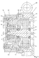
- Fig. 1 shows a hoist drive, in which a Internal rotor electric motor 1 drives an output shaft 2, which in turn has a drive shaft 3 with an inner central wheel 4 drives a planetary gear.
- the output shaft 2, the drive shaft 3 and the inner central wheel 4 can be made individually or in one piece.
- the electric motor 1 is with a cover 5, which the Winding 6 of the electric motor 1 takes up in a stator housing 7 inserted and fixed in a rotationally fixed manner.
- the cover 5 has a bearing 8, by means of which one side of the Output shaft 2 is mounted.
- the lid 5 has an opening 9, in which a speed sensor within the axial Extension of the hoist drive can be installed.
- the stator housing 7 has openings shown in FIG.
- the brake 11 is in connection with the output shaft 2 and encloses the electric motor 1 bell-shaped.
- the brake 11 is in axial direction between the winding 6 of the electric motor 1 and the end wall 12 of the reduction gear arranged.
- the brake can also be designed as a disc brake his.
- the end wall 12 is rotatably connected to the stator housing 7 connected and takes the storage 13 Forces of the pulley 14.
- the inner central wheel 4 drives double planet wheels 15, which are in meshing connection stands with a fixed ring gear 16.
- the planetary stage is designed with helical teeth, to enable quiet operation.
- the Bridge 17 is the output of the double planetary stage and stands in connection with the pulley 14.
- the reduction gear has a closed oil chamber, which by Sealing means 18 is sealed.
- the end wall 12 on the one hand and the cover 5, on the other hand, form the outer borders of the space containing the brake 11 and the electric motor 1 include.
- the stator housing 7 has an actuating device 20 for the brake on and fasteners, around the hoist drive on and at stationary Attach documents.
- FIG. 2 shows the arrangement of the brake, in which springs 23 press the brake shoes 22 onto the friction surface 10.
- the brake shoes 22 can be released against the spring force via the actuating means 20.
Landscapes
- Engineering & Computer Science (AREA)
- Power Engineering (AREA)
- General Engineering & Computer Science (AREA)
- Mechanical Engineering (AREA)
- Civil Engineering (AREA)
- Structural Engineering (AREA)
- Physics & Mathematics (AREA)
- Electromagnetism (AREA)
- Connection Of Motors, Electrical Generators, Mechanical Devices, And The Like (AREA)
- Cage And Drive Apparatuses For Elevators (AREA)
- Braking Arrangements (AREA)
Description
Die Erfindung betrifft einen Hebezeugantrieb mit antreibendem Motor, Planetengetriebe und Bremse nach dem Oberbegriff des ersten Anspruches.The invention relates to a hoist drive with a driving Motor, planetary gear and brake after Preamble of the first claim.
Ein derartiger Hebezeugantrieb ist bereits aus der FR-A-2 260 526 bekannt.Such a hoist drive is already known from FR-A-2 260 526.
Hebezeugantriebe für Personen und Güter sind weit verbreitet, z. B. als Aufzüge, Seilwinden usw. Da sich die Aufzüge mit niedrigen Geschwindigkeiten bewegen, ist die Drehzahl der Abtriebswelle des Hebezeugantriebs entsprechend niedrig. Die erforderlichen Drehmomente können von Elektromotoren mit günstigem Wirkungsgrad nicht direkt zur Verfügung gestellt werden, sondern erfordern ein nachgeschaltetes Untersetzungsgetriebe. Die Bremsen, welche die Aufgabe haben, den Hebezeugantrieb abzubremsen, müßten ohne Untersetzungsgetriebe in der Lage sein, das Abtriebsdrehmoment zu bremsen bzw. zu halten und würden einen erheblichen Bauraum benötigen. Da die Aufzugkabine entstehende Geräusche verstärkt, ist der Hebezeugantrieb besonders laufruhig zu gestalten. Alle Bestandteile des Antriebs sind oftmals unter schwierig zugänglichen Bedingungen auf engstem Raum zu installieren. Besteht die Möglichkeit, den Hebezeugantrieb im Aufzugschacht zu installieren, kann der sonst notwendige Maschinenraum entfallen. Diese Hebezeugantriebe für maschinenraumlose Aufzüge müssen eine extrem kurze Baulänge aufweisen. Im Servicefall sollte zumindest der Elektromotor abbaubar sein, ohne daß der komplette Hebezeugantrieb von der Aufzugkabine getrennt werden muß.Hoist drives for people and goods are widespread, z. B. as lifts, winches, etc. Since the Moving elevators at low speeds is that Speed of the output shaft of the hoist drive accordingly low. The required torques can vary from Electric motors with low efficiency are not directly available Be made available, but require a downstream Reduction gear. The brakes that the The task of braking the hoist drive should be without Reduction gear to be able to reduce the output torque to brake or hold and would be a significant Require installation space. Noises arising from the elevator car reinforced, the hoist drive is particularly quiet to design. All components of the drive are often in difficult to access conditions in a confined space to install. There is the possibility of the hoist drive To install in the elevator shaft, the otherwise necessary Machine room is eliminated. These hoist drives for machine room-less elevators must have an extremely short overall length exhibit. When servicing, at least the electric motor should be degradable without the complete hoist drive from the elevator car must be separated.
Ein Antrieb der eingangs beschriebenen Art ist in der DE 31 12 090 A1 offenbart. Dieser Antrieb besteht aus einem hoch übersetzenden Getriebe mit geringer Zahndifferenz zwischen dem befestigten Festrad und dem Abtriebsrad der Seilscheibe. Diese Art des Untersetzungsgetriebes erfordert bei einer Umdrehung der Seilscheibe eine Vielzahl von Zahneingriffen. Da jeder Zahneingriff im Hebezeugantrieb eine Schwingungsanregung und somit Geräusch erzeugt, sind bei diesem Hebezeugantrieb besondere geräuschdämpfende Maßnahmen erforderlich. Dem hoch übersetzenden Getriebe ist in axialer Richtung ein Innenläufer-Elektromotor und eine Bremse nachgeschaltet, wobei die Wicklung des Innenläufer-Motors direkt an der Trennwand des Motors zum Untersetzungsgetriebe angeordnet ist. Dadurch wird das Untersetzungsgetriebe zusätzlich durch die Verlustwärme der Motorwicklung erwärmt. Dies führt zu einer ungünstigen Temperaturentwicklung im Getriebe. Indem die Bremse einerseits am Motorgehäuse und die Lagerung der Treibscheibe andererseits am Getriebegehäuse angebracht sind, ist die axiale Erstrekkung dieses Hebezeugantriebs groß.A drive of the type described above is in the DE 31 12 090 A1 discloses. This drive consists of one high gear ratio with small tooth difference between the fixed fixed wheel and the driven wheel of the pulley. This type of reduction gear requires one turn of the sheave a variety of meshes. Because each tooth engagement in the hoist drive is one Vibration excitation and thus noise are generated this hoist drive special noise-damping measures required. The high gear ratio is in axial direction an internal rotor electric motor and Brake connected downstream, the winding of the inner rotor motor directly on the partition of the motor to the reduction gear is arranged. This will make the reduction gear additionally by the heat loss of the motor winding heated. This leads to an unfavorable temperature development in the transmission. By the brake on the one hand Motor housing and the bearing of the traction sheave on the other hand are attached to the gear housing, is the axial extent this hoist drive is big.
Aus der DE 197 39 001 C1 ist ein Aufzugantrieb offenbart, bei welchem die Bremse des Aufzugantriebs nicht dem Antriebsmotor nachgeschaltet angeordnet ist, sondern innerhalb der axialen Erstreckung des Antriebs auf eine Trommel wirkt. Da diese Trommel gleichzeitig die Aufgabe des Außenläufers des Elektromotors wahrnimmt, ist bei diesem Antrieb ein gleichbleibender Wirkungsgsrad nicht gegeben, da durch die Wärmeeinwirkung der Bremse die Außenläufertrommel erwärmt wird und sich der Spalt zwischen Wicklung und Außenläufer verändert.DE 197 39 001 C1 discloses an elevator drive, where the brake of the elevator drive is not that Drive motor is arranged downstream, but within the axial extension of the drive on a drum acts. Because this drum also serves as the external rotor of the electric motor is in this drive a constant degree of effectiveness is not given because of the heat from the brake heats the external rotor drum and there is a gap between the winding and the external rotor changed.
Der vorliegenden Erfindung liegt die Aufgabe zugrunde, einen Hebezeugantrieb zu schaffen, welcher sich in axialer Länge durch eine kompakte Bauform auszeichnet, wenig Geräuschemission erzeugt, einen gleichbleibenden Wirkungsgrad aufweist sowie im Servicefall mit geringem Aufwand zugänglich ist.The present invention is based on the object to create a hoist drive, which is in axial Length is characterized by a compact design, little noise emission generates a constant efficiency and accessible with little effort in the event of service is.
Die Aufgabe wird mit einem, auch die kennzeichnenden Merkmale des Hauptanspruchs aufweisenden, gattungsgemäßen Hebezeugantrieb gelöst.The task comes with one, including the distinctive Features of the main claim, generic Hoist drive released.
Erfindungsgemäß wird als Untersetzungsgetriebe ein Planetengetriebe mit Doppelplaneten verwendet, welches sich dadurch auszeichnet, daß die benötigte Übersetzung mit einer geringen Anzahl von Zahneingriffen und somit einer geringen Geräuschemission erreicht wird. Die Bremse des Hebezeugantriebs ist axial zwischen dem Elektromotor und dem Untersetzungsgetriebe angeordnet, wobei die Bremse den Elektromotor glockenförmig umgibt und die Reibfläche der Bremse sich innerhalb der axialen Erstreckung des Elektromotors befindet. Die Bremse steht in Verbindung mit der Welle des Antriebsmotors. Indem die Bremse das innere Zentralrad des Untersetzungsgetriebes abbremst und somit dem Untersetzungsgetriebe vorgeschaltet ist, kann die Bremse kleiner dimensioniert werden. Da die Bremse sich zwischen dem Untersetzungsgetriebe und dem Antriebsmotor befindet, die Reibfläche der Bremse sich im Bereich des Antriebsmotors befindet, wird verhindert, daß der Antriebsmotor seine Verlustwärme an das Getriebe abgibt. Indem sich die Reibfläche der Bremse innerhalb der axialen Erstreckung des Antriebsmotors befindet, ist es möglich, eine sehr kompakte Antriebseinheit zu schaffen. Da die Bremse unabhängig vom Elektromotor angeordnet ist, ist gewährleistet, daß der Spalt zwischen Rotor und Stator auch bei Erwärmung der Bremse gleichbleibend und somit ein konstanter Wirkungsgrad des Elektromotors gegeben ist. Das Untersetzungsgetriebe ist an ein Ständergehäuse angeschraubt, welches einerseits die Betätigungseinrichtung der Bremse aufnimmt und andererseits Möglichkeiten zur Befestigung des Hebezeugantriebs, vorzugsweise im Aufzugschacht, aufweist. In das Ständergehäuse ist der Antriebsmotor eingeschoben und kann im Servicefall, ohne daß der Hebezeugantrieb von der Aufzugkabine getrennt werden muß, entnommen werden. Der Antriebsmotor ist an seiner dem Untersetzungsgetriebe abgewandten Seite dergestalt ausgeführt, daß ein Drehzahlgeber, vorzugsweise ein Inkrementalgeber, innerhalb der axialen Erstreckung des Antriebsmotors auf der Abtriebswelle des Antriebsmotors angebracht werden kann. Die Abschlußwand des Untersetzungsgetriebes zur Bremse ist so ausgeführt, daß die Kräfte der Treibscheibe des Hebezeugantriebs über eine Lagerung aufgenommen werden können sowie daß diese Abschlußwand die Hohlradverzahnung der Doppelplanetenstufe aufnimmt und daß diese Abschlußwand die Abdichtung und Lagerung der Antriebswelle des Untersetzungsgetriebes beinhaltet. Die Lagerung der Treibscheibe ist in radialer Richtung über die radiale Erstreckung der Doppelplanetenstufe gestellt, so daß sie in axialer Richtung im Bereich der Doppelplanetenstufe, mindestens jedoch ein Teil der Lagerung der Treibscheibe innerhalb der axialen Erstreckung der Doppelplanetenstufe, angeordnet werden kann. Indem die Lagerung der Treibscheibe im Bereich der Doppelplanetenstufe angeordnet werden kann, ist es möglich, in axialer Richtung einen sehr kompakten Antrieb zu schaffen. Die Antriebswelle des Untersetzungsgetriebes, welche mit der Abtriebswelle des Antriebsmotors verbunden ist, kann mit dieser auch einstückig ausgeführt sein. Alle Kräfte, welche auf die Abschlußwand wirken, werden auf das Ständergehäuse übertragen, welches mit der Abschlußwand in Verbindung steht. Das Ständergehäuse kann in radialer Richtung zwei gegenüberliegende Öffnungen aufweisen, durch welche zwei Bremsbacken über Federkraft auf die Bremstrommel wirken bzw. die Bremsbacken betätigt werden können. Im Servicefall können dann diese Bremsbacken nach außen abgenommen werden, ohne daß weitere wesentliche Teile des Hebezeugantriebs entfernt werden müssen.According to the invention, a reduction gear is used Planetary gear with double planet used, which is characterized in that the required translation with a low number of meshes and thus a small number Noise emission is achieved. The brake of the hoist drive is axial between the electric motor and the Reduction gear arranged, the brake the Electric motor surrounds bell-shaped and the friction surface of the Brake yourself within the axial extension of the electric motor located. The brake is connected to the Drive motor shaft. By the brake the inner central wheel of the reduction gear brakes and thus the Reduction gear is connected upstream, the brake be dimensioned smaller. Since the brake is between the reduction gear and the drive motor, the friction surface of the brake is in the area of the drive motor is prevented that the drive motor Gives off heat loss to the gearbox. By making the friction surface the brake within the axial extension of the Drive motor, it is possible to have a very compact To create drive unit. Because the brake regardless of Electric motor is arranged, it is ensured that the Gap between rotor and stator even when the Brake constant and therefore constant efficiency of the electric motor is given. The reduction gear is screwed to a stand housing, which on the one hand the actuator of the brake receives and on the other hand Possibilities for fastening the hoist drive, preferably in the elevator shaft. In the stand housing the drive motor is inserted and can be serviced, without the hoist drive from the elevator car must be taken out. The drive motor is on its side facing away from the reduction gear executed such that a speed sensor, preferably an incremental encoder, within the axial extension of the Drive motor on the output shaft of the drive motor can be attached. The end wall of the reduction gear to the brake is designed so that the forces of Traction sheave of the hoist drive added via a bearing can be and that this end wall the ring gear teeth the double planetary stage and that this End wall sealing and mounting the drive shaft of the reduction gear includes. Warehousing the traction sheave is radial over the radial Extend the double planetary stage, so that they in axial direction in the area of the double planetary stage, at least however part of the traction sheave storage within the axial extension of the double planetary stage can be. By storing the traction sheave in the Area of the double planetary stage can be arranged it is possible to have a very compact drive in the axial direction to accomplish. The drive shaft of the reduction gear, which with the output shaft of the drive motor is connected, can also be made in one piece with this his. All forces that act on the end wall become transferred to the stator housing, which with the end wall communicates. The stand housing can be in have two opposite openings in the radial direction, through which two brake shoes on the spring force Brake drum act or the brake shoes are actuated can. In the event of service, these brake shoes can then be adjusted can be removed from the outside without further essential parts of the hoist drive must be removed.
Weitere vorteilhafte Ausgestaltungen sind den Ausführungsbeispielen
zu entnehmen.
Es zeigen:
- Fig. 1
- einen Schnitt durch einen Hebezeugantrieb in Längsrichtung und
- Fig. 2
- einen Schnitt durch einen Hebezeugantrieb in Querrichtung.
Show it:
- Fig. 1
- a section through a hoist drive in the longitudinal direction and
- Fig. 2
- a section through a hoist drive in the transverse direction.
Fig. 1 zeigt einen Hebezeugantrieb, bei welchem ein
Innenläufer-Elektromotor 1 eine Abtriebswelle 2 antreibt,
welche wiederum eine Antriebswelle 3 mit einem inneren Zentralrad
4 eines Planetengetriebes antreibt. Die Abtriebswelle
2, die Antriebswelle 3 und das innere Zentralrad 4
können wahlweise einzeln oder einstückig ausgeführt sein.
Der Elektromotor 1 ist mit einem Deckel 5, welcher die
Wicklung 6 des Elektromotors 1 aufnimmt, in ein Ständergehäuse
7 eingeschoben und drehfest befestigt. Der Deckel 5
besitzt eine Lagerung 8, mittels welcher eine Seite der
Abtriebswelle 2 gelagert ist. Der Deckel 5 weist eine Öffnung
9 auf, in welche ein Drehzahlgeber innerhalb der axialen
Erstreckung des Hebezeugantriebs eingebaut werden kann.
Das Ständergehäuse 7 weist in Fig. 2 dargestellte Öffnungen
21 auf, durch welche Bremsbacken 22 auf die Reibfläche
10 einer Bremse 11 einwirken können. Die Bremse 11
steht in Verbindung mit der Abtriebswelle 2 und umschließt
den Elektromotor 1 glockenförmig. Die Bremse 11 ist in
axialer Richtung zwischen der Wicklung 6 des Elektromotors
1 und der Abschlußwand 12 des Untersetzungsgetriebes
angeordnet. Die Bremse kann auch als Scheibenbremse ausgeführt
sein. Die Abschlußwand 12 ist drehfest mit dem Ständergehäuse
7 verbunden und nimmt über eine Lagerung 13 die
Kräfte der Seilscheibe 14 auf. Das innere Zentralrad 4
treibt Doppelplanetenräder 15 an, welche in kämmender Verbindung
mit einem feststehenden Hohlrad 16 steht. Vorzugsweise
ist die Planetenstufe mit einer Schrägverzahnung ausgeführt,
um einen geräuscharmen Betrieb zu ermögichen. Der
Steg 17 ist der Abtrieb der Doppelplanetenstufe und steht
in Verbindung mit der Seilscheibe 14. Das Untersetzungsgetriebe
weist einen geschlossenen Ölraum auf, welcher durch
Dichtungsmittel 18 abgedichtet wird. Die Antriebswelle 3
oder die Abtriebswelle 2 werden mit Hilfe einer Lagerung 19
in der Abschlußwand 12 gelagert. Die Abschlußwand 12 einerseits
und der Deckel 5 andererseits bilden die äußeren Berandungen
des Raumes, welcher die Bremse 11 und den Elektromotor
1 beinhalten. Das Ständergehäuse 7 weist eine Betätigungseinrichtung
20 für die Bremse auf sowie Befestigungsmittel,
um den Hebezeugantrieb auf und an ortsfesten
Unterlagen zu befestigen.Fig. 1 shows a hoist drive, in which a
Internal rotor
Fig. 2 zeigt die Anordnung der Bremse, bei welcher
Federn 23 die Bremsbacken 22 auf die Reibfläche 10 drücken.
Über die Betätigungsmittel 20 können die Bremsbacken 22
gegen die Federkraft gelöst werden.
Indem die Bremse durch Öffnungen 21 eingreift, ist es möglich,
nach Lösen der Federn 23 im Wartungsfall die Bremsbacken
22 nach außen zu schwenken, ohne weitere Demontagen
am Antrieb durchführen zu müssen. FIG. 2 shows the arrangement of the brake, in which springs 23 press the
By engaging the brake through
- 11
- Elektromotorelectric motor
- 22
- Abtriebswelleoutput shaft
- 33
- Antriebswelledrive shaft
- 44
- inneres Zentralradinner central wheel
- 55
- Deckelcover
- 66
- Wicklungwinding
- 77
- StändergehäuseThe stator frame
- 88th
- Lagerungstorage
- 99
- Öffnungopening
- 1010
- Reibflachefriction surface
- 1111
- Bremsebrake
- 1212
- Abschlußwandend wall
- 1313
- Lagerungstorage
- 1414
- Seilscheibesheave
- 1515
- Doppelplanetenraddouble planet
- 1616
- Hohlradring gear
- 1717
- Stegweb
- 1818
- Dichtungsmittelsealant
- 1919
- Lagerungstorage
- 2020
- Betätigungsmittelactuating means
- 2121
- Öffnungopening
- 2222
- Bremsbackenbrake shoes
- 2323
- Federfeather
Claims (8)
- Elevator drive, in which a drive motor (1) drives a reduction gear unit and can be braked by a brake 11), wherein the reduction gear unit is a planetary gear unit with dual planet wheels (15), and an inner central wheel (3) of the planetary gear unit is driven by a drive motor (1), wherein a planet carrier (17) forms an output drive, characterised in that at least a part of a mounting (13), which is connected to the output drive, is disposed outside of the dual planet wheels (15) and within the axial extent of the dual planet wheels (15) in the radial direction.
- Elevator drive according to Claim 1, characterised in that the brake (1) is connected upstream of the reduction gear unit.
- Elevator drive according to Claim 1, characterised in that the drive motor (1) is disposed inside a stator housing (7).
- Elevator drive according to Claim 1, characterised in that a space in which the drive motor (1) is located is bounded on one side by a cover (5), which contains a winding (6) of an electric motor, and on the other by a closing wall (12), which takes up the forces of a rope pulley (14) via a mounting (13) and is connected to a ring gear (16).
- Elevator drive according to Claim 1, characterised in that the reduction gear unit comprises a closed lubricant reservoir sealed by sealing means (18), which are placed on a closing wall (12), which takes up the forces of a rope pulley (14) via a mounting (13) and is connected to a ring gear (16).
- Elevator drive according to Claim 1, characterised in that a stator housing (7) comprises opposite openings (21), through which at least one brake shoe (22), which is accessible from outside of the elevator drive, acts on a brake (11).
- Elevator drive according to Claim 1, characterised in that a brake (11) is disposed between the reduction gear unit and the drive motor (1) in the axial direction.
- Elevator drive according to Claim 1, characterised in that a stator housing (7) comprises means for fastening the elevator drive.
Applications Claiming Priority (3)
| Application Number | Priority Date | Filing Date | Title |
|---|---|---|---|
| DE19908092A DE19908092A1 (en) | 1999-02-25 | 1999-02-25 | Hoist drive |
| DE19908092 | 1999-02-25 | ||
| PCT/EP2000/001401 WO2000050330A1 (en) | 1999-02-25 | 2000-02-21 | Drive for a lifting device |
Publications (2)
| Publication Number | Publication Date |
|---|---|
| EP1156978A1 EP1156978A1 (en) | 2001-11-28 |
| EP1156978B1 true EP1156978B1 (en) | 2004-01-21 |
Family
ID=7898790
Family Applications (1)
| Application Number | Title | Priority Date | Filing Date |
|---|---|---|---|
| EP00916852A Expired - Lifetime EP1156978B1 (en) | 1999-02-25 | 2000-02-21 | Drive for a lifting device |
Country Status (4)
| Country | Link |
|---|---|
| EP (1) | EP1156978B1 (en) |
| DE (2) | DE19908092A1 (en) |
| ES (1) | ES2215041T3 (en) |
| WO (1) | WO2000050330A1 (en) |
Families Citing this family (2)
| Publication number | Priority date | Publication date | Assignee | Title |
|---|---|---|---|---|
| CN1310822C (en) * | 2004-07-05 | 2007-04-18 | 黄民英 | Dragging machine of elevator |
| CN103867652B (en) * | 2014-03-03 | 2016-04-27 | 青岛力克川液压机械有限公司 | A kind of crawler unit |
Family Cites Families (7)
| Publication number | Priority date | Publication date | Assignee | Title |
|---|---|---|---|---|
| FR511877A (en) * | 1919-06-17 | 1921-01-06 | Otis Pifre Ateliers Sa | Gear changing device for lifting or other devices, driven electrically |
| FR2260526A1 (en) * | 1974-02-13 | 1975-09-05 | Mo Inzh Str | Lift winch with guide pulley - is driven via epicyclic reduction gear and acting as its planet carrier |
| DE3112090A1 (en) * | 1981-03-27 | 1983-02-03 | Heinz 2000 Hamburg Buchmeier | Lift gearing with an electric motor |
| FI82434C (en) * | 1988-07-07 | 1991-03-11 | Kone Oy | Elevator machinery. |
| US5435209A (en) * | 1992-06-26 | 1995-07-25 | Wittur Aufzugteile Gmbh & Co. | Drive unit for a hoisting apparatus, in particular for a passenger or freight elevator |
| DE4323361A1 (en) * | 1993-07-13 | 1995-01-19 | Dewitta Spezialmaschf | Drive apparatus for lifting gear, in particular for lifts |
| DE19739001C1 (en) * | 1997-09-06 | 1998-10-15 | Ziehl Abegg Gmbh & Co Kg | Lift drive arrangement with horizontal shaft type electric drive motor |
-
1999
- 1999-02-25 DE DE19908092A patent/DE19908092A1/en not_active Withdrawn
-
2000
- 2000-02-21 ES ES00916852T patent/ES2215041T3/en not_active Expired - Lifetime
- 2000-02-21 EP EP00916852A patent/EP1156978B1/en not_active Expired - Lifetime
- 2000-02-21 DE DE50005078T patent/DE50005078D1/en not_active Expired - Lifetime
- 2000-02-21 WO PCT/EP2000/001401 patent/WO2000050330A1/en active IP Right Grant
Also Published As
| Publication number | Publication date |
|---|---|
| ES2215041T3 (en) | 2004-10-01 |
| WO2000050330A1 (en) | 2000-08-31 |
| DE19908092A1 (en) | 2000-08-31 |
| EP1156978A1 (en) | 2001-11-28 |
| DE50005078D1 (en) | 2004-02-26 |
Similar Documents
| Publication | Publication Date | Title |
|---|---|---|
| EP0578069B1 (en) | Driving equipment for a hoist, in particular for a goods or passenger elevator | |
| EP0706968B1 (en) | Drive unit for a lifting device | |
| EP0745553A1 (en) | Lift driving unit | |
| EP1747930B1 (en) | Drive unit | |
| DE3922272A1 (en) | ELEVATOR UNIT | |
| EP0834463A1 (en) | Compact drive for elevator | |
| DE10317949B4 (en) | Electrically operated brake assembly for a transmission | |
| EP0078874B1 (en) | Hoist for a passenger or goods elevator | |
| EP0884267A2 (en) | Drive unit for a hoisting device | |
| DE3922274C2 (en) | ||
| EP1156978B1 (en) | Drive for a lifting device | |
| DE10361296A1 (en) | Self-reinforcing electromechanical vehicle brake | |
| WO2001028911A1 (en) | Lift with a car attached to a support | |
| WO1998021495A1 (en) | Driving mechanism for a stationary transporting device | |
| DE3112090A1 (en) | Lift gearing with an electric motor | |
| WO2016173687A1 (en) | Transmission system | |
| EP1089935B1 (en) | Hoist drive | |
| DE3342172C2 (en) | Electric travel drive for a crane or the chassis of a hoist etc. | |
| EP1431233B1 (en) | Hydraulic rope drive for elevators | |
| JP3284752B2 (en) | Hoist with fine speed mechanism | |
| DE19829532A1 (en) | Hoist drive used in lifts, cable winches, etc | |
| EP4082096A1 (en) | Drive unit and construction machine and/or material handling machine having such a drive unit | |
| DE202005020632U1 (en) | Drive unit, has brake arranged between steering and traction motors for braking vehicle wheel, where rotary and stationary components of brake are connected with drive shaft of traction motor and motor housing, respectively | |
| WO2023099026A1 (en) | Drive, having a transmission with a transmission housing, an electromagnetically actuatable brake assembly and an electric motor | |
| WO2023099025A1 (en) | Drive, having a transmission with a transmission housing, an electromagnetically actuatable brake assembly and an electric motor |
Legal Events
| Date | Code | Title | Description |
|---|---|---|---|
| PUAI | Public reference made under article 153(3) epc to a published international application that has entered the european phase |
Free format text: ORIGINAL CODE: 0009012 |
|
| 17P | Request for examination filed |
Effective date: 20010508 |
|
| AK | Designated contracting states |
Kind code of ref document: A1 Designated state(s): AT BE CH CY DE DK ES FI FR GB GR IE IT LI LU MC NL PT SE |
|
| GRAP | Despatch of communication of intention to grant a patent |
Free format text: ORIGINAL CODE: EPIDOSNIGR1 |
|
| GRAS | Grant fee paid |
Free format text: ORIGINAL CODE: EPIDOSNIGR3 |
|
| GRAA | (expected) grant |
Free format text: ORIGINAL CODE: 0009210 |
|
| AK | Designated contracting states |
Kind code of ref document: B1 Designated state(s): DE ES GB |
|
| REG | Reference to a national code |
Ref country code: GB Ref legal event code: FG4D Free format text: NOT ENGLISH |
|
| REG | Reference to a national code |
Ref country code: IE Ref legal event code: FG4D Free format text: GERMAN |
|
| REF | Corresponds to: |
Ref document number: 50005078 Country of ref document: DE Date of ref document: 20040226 Kind code of ref document: P |
|
| GBT | Gb: translation of ep patent filed (gb section 77(6)(a)/1977) |
Effective date: 20040216 |
|
| REG | Reference to a national code |
Ref country code: IE Ref legal event code: FD4D |
|
| REG | Reference to a national code |
Ref country code: ES Ref legal event code: FG2A Ref document number: 2215041 Country of ref document: ES Kind code of ref document: T3 |
|
| PLBE | No opposition filed within time limit |
Free format text: ORIGINAL CODE: 0009261 |
|
| STAA | Information on the status of an ep patent application or granted ep patent |
Free format text: STATUS: NO OPPOSITION FILED WITHIN TIME LIMIT |
|
| 26N | No opposition filed |
Effective date: 20041022 |
|
| PGFP | Annual fee paid to national office [announced via postgrant information from national office to epo] |
Ref country code: DE Payment date: 20110216 Year of fee payment: 12 |
|
| PGFP | Annual fee paid to national office [announced via postgrant information from national office to epo] |
Ref country code: ES Payment date: 20110315 Year of fee payment: 12 Ref country code: GB Payment date: 20110216 Year of fee payment: 12 |
|
| GBPC | Gb: european patent ceased through non-payment of renewal fee |
Effective date: 20120221 |
|
| REG | Reference to a national code |
Ref country code: DE Ref legal event code: R119 Ref document number: 50005078 Country of ref document: DE Effective date: 20120901 |
|
| PG25 | Lapsed in a contracting state [announced via postgrant information from national office to epo] |
Ref country code: GB Free format text: LAPSE BECAUSE OF NON-PAYMENT OF DUE FEES Effective date: 20120221 |
|
| PG25 | Lapsed in a contracting state [announced via postgrant information from national office to epo] |
Ref country code: DE Free format text: LAPSE BECAUSE OF NON-PAYMENT OF DUE FEES Effective date: 20120901 |
|
| REG | Reference to a national code |
Ref country code: ES Ref legal event code: FD2A Effective date: 20130708 |
|
| PG25 | Lapsed in a contracting state [announced via postgrant information from national office to epo] |
Ref country code: ES Free format text: LAPSE BECAUSE OF NON-PAYMENT OF DUE FEES Effective date: 20120222 |