FIELD OF THE INVENTION
The present invention relates to an image
processing system which includes a printer device to
which a detachable card device is attached, and which
has a connection function, and a host device and, more
particularly, to an image processing system in which a
card device includes a communication controller for
exchanging information with a host device, and a
printer device prints in accordance with information
from the card device, an image data processing method,
and a storage medium which stores a program module that
makes a computer implement that method.
BACKGROUND OF THE INVENTION
In recent years, information devices such as
personal computers (to be referred to as PCs
hereinafter) and the like have increasingly prevailed
in homes. Also, an infrastructure environment such as
the Internet or the like with which everyone can easily
use information on the network has been built, and
digital home appliances such as digital cameras,
digital video cameras, and the like have proliferated.
Under such circumstances, printer devices that can
obtain a desired printout have rapidly spread to homes.
A so-called multimedia environment that allows
the user to print or to insert images sensed by digital
cameras and the like in e-mail messages, home pages,
and the like via the Internet by connecting such
devices to the PC is ready. Upon building use
environments of such devices, installation processes
are often required. That is, the user must install an
application program to be used, a so-called device
driver required to use a device to be connected, and
the like in the PC in advance, and then must connect
the device to a predetermined I/O port. That is, the
user can use the required functions after he or she
successfully completes such installation processes.
However, since these processes require some
expert knowledge and correct understanding of manuals
and the like, such requirements make beginners,
children, aged users, and the like harder to use such
functions and impose mental loads on them.
The conventional arrangement will be explained
below with reference to the accompanying drawings.
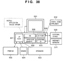
Fig. 38 is a view for explaining an example of the
conventional arrangement, and shows a system
arrangement using a personal computer (PC). Reference
numeral 500 denotes a PC main body. A monitor 501 is
connected to a video circuit (not shown), and can
output text and images.
As shown in Fig. 38, many devices are connected
to the PC main body: a keyboard 503 for inputting text
and the like, a mouse 504 as one of pointing devices
for operating an input instruction position such as a
pointer on a screen, and a printer 505 used to obtain a
desired printout are connected to an I/F port 507. The
PC main body comprises a CD (compact disk reader) 506
which can read the contents of a CD-ROM (compact disk
ROM) that records information required to install an
application and the like, a floppy disk device (not
shown), a large-size memory 502 which comprises a hard
disk or a flash ROM (electrically programmable memory)
for storing application programs, device drivers, and
the like installed using information recorded on a
CD-ROM in the CD 506 and floppy disk, and a work memory,
an external I/F 510 which comprises a modem used to
connect an external network 511 such as the Internet or
the like, a network communication circuit, and the like,
and an I/O port 508 used to connect a digital home
appliance 512 such as a digital camera or the like, and
other external devices 509.
In the conventional arrangement, when the user
connects and uses a desired application program, and
devices such as a printer, digital camera, and the like
he or she purchased, he or she must install program
information/data supplied via storage media such as a
floppy disk, CD-ROM, and the like which come with them
or via a file acquired via the Internet or the like in
the hard disk or the like. For this reason, upon using
the application and the devices connected, the storage
capacity of the expensive hard disk decreases.
Before the user begins to use the desired
application or device connected after the installation
processes, he or she must often restart the personal
computer, thus requiring a long setup time until he or
she can begin to use them.
Upon connecting various devices shown in Fig. 38,
the user must often attach option boards such as an I/F
port, I/O card, external I/F, and the like to the PC
main body.
Upon attaching such option boards, in most cases,
the user must temporarily turn off the power supplies
of devices already connected to the PC, and the power
supply of the PC itself, open the housing cover of the
PC main body, insert an option board into a
predetermined I/O slot and fix it using screws or the
like, close the housing cover again, and turn on the
power supply to start the system. After that, in order
to use the inserted option board, the user must install
an optimal device driver and the like in the hard disk
or the like, restart the system once more in the worst
case, and then install a device driver and the like of
a required device to be connected to that option board,
resulting in troublesome operations.
Such option card or a control circuit of a device
built in the PC main body often incorporates a ROM or
the like so as to control various functions. In recent
years, a flash ROM (electrically erasable/programmable
ROM) is used as such ROM so that the ROM contents can
be rewritten, and the user can debug software and
upgrade the version of software after purchase.
However, such rewrite operation of the ROM
contents is normally done by the user, and is provided
at user's own risk. That is, this operation requires
some expert knowledge.
For example, confirmation of the version of a ROM
to be rewritten, acquisition of an appropriate
version-up program, rewrite operation in a specific
operation environment, and the like are required, thus
requiring close attention. If the user makes wrong
operation, the system can no longer be started or some
or all functions are no longer available in the worst
case.
That is, such version-up service method is
difficult for and not welcomed by end users.
For example, a function "to print an image sensed
by a digital camera" in the conventional arrangement
will be examined below. The user connects a digital
camera and printer to the PC, and installs device
drivers, applications, and the like required for these
devices in a hard disk or the like in advance. The
user then selects and launches a predetermined
installed application or the like to temporarily
download a desired image from the digital camera to a
storage device such as a hard disk or the like of the
PC, and inputs a print instruction after connecting the
printer, thus obtaining a printout. That is, in order
to implement a relatively simple function "to take and
print a picture" that the user wants, the user must
perform a tremendous amount of work.
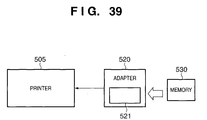
Figs. 39 and 40 are views for explaining another
conventional arrangement. The conventional arrangement
shown in Figs. 39 and 40 is an example that improves
convenience of the function "to print an image sensed
by a digital camera", and the printer comprises a
so-called direct print function.
In Figs. 39 and 40, a memory 530 is a memory
device which can be attached to a digital camera, and
comprises a nonvolatile memory. An image sensed by a
digital camera is saved in the memory, and when the
sensed image is to be printed, the memory 530 is
detached from the digital camera, and is attached to an
adapter 520 or printer 540. Then, print operation is
made at a control panel 521 or 541 to print out a
desired image.
So-called JPEG data is used as image data saved
in the memory 530, and the adapter 520 or printer 540
comprises an image processing function to print out
such image data. These devices print out image
information such as JPEG data while rasterizing,
reducing, or enlarging it.
In order to generate print data at high speed via
an image process, color process, and the like, the
aforementioned device comprises a high-speed CPU,
complicated hardware, and a large-size memory,
resulting in high device cost. Also, since the control
panel 520 or 541 has an LCD (liquid crystal display),
many operation buttons, and the like, the device size
increases due to an increase in physical area of the
operation portion, and the operability suffers due to
hard-to-see display of operation designation states and
the like on a compact display such as an LCD or the
like, considering the fact that the device cost
increases.
In the conventional arrangement, upon printing
using the printer device, the user must set the type of
print medium such as a paper sheet to be used in a
print process in correspondence with the output print
quality of a target image he or she wants to print out.
If the user makes wrong setups, a printout against his
or her expectation is obtained. For example, when an
ink-jet printer is used, the output print quality
deteriorates due to tincture, color mixing, ink
overflow, and the like.
On the other hand, print media used to output
high-quality images are normally expensive, and such
media may often be wasted by erroneous operations.
In the conventional arrangement, when the user
takes a family photo in, e.g., a living room using a
digital camera and wants to immediately print it out,
he or she must go to a room where the personal computer
is set, resulting in poor convenience.
SUMMARY OF THE INVENTION
The present invention has been proposed to solve
the conventional problems, and has as its object to
provide a home-use image processing system everyone can
easily use, from which tedious processes such as
installation processes and the like are excluded as
much as possible.
In order to solve the above problems and to
achieve the object of the present invention, an image
processing system or the like according to the present
invention is characterized mainly by the following
arrangement.
That is, in an image processing system built by
connecting a host device which reads out and executes
program data stored in a storage medium, and a device
added with a card device function, the device connected
to the system comprises:
An image data processing method for processing
data by exchanging information between a host device
which reads out and executes program data stored in a
storage medium, and a device added with a card device
function, comprises:
In a computer readable storage medium which
stores a program module for making a computer implement
an image data processing method for processing data by
exchanging information between a host device which
reads out and executes program data stored in a storage
medium, and a device added with a card device function,
the program module comprises:
In an image processing system built by connecting
a host device which reads out and executes program data
stored in a storage medium, and a device added with a
card device function, the device connected to the
system comprises:
An image data processing method for processing
data by exchanging information between a host device
which reads out and executes program data stored in a
storage medium, and a device added with a card device
function, comprises:
In a computer readable storage medium which
stores a program module for making a computer implement
an image data processing method for processing data by
exchanging information between a host device which
reads out and executes program data stored in a storage
medium, and a device added with a card device function,
the program module comprises:
In an image processing system built by connecting
a host device which reads out and executes program data
stored in a storage medium, and a device added with a
card device function, the device connected to the
system comprises:
An image data processing method for processing
data by exchanging information between a host device
which reads out and executes program data stored in a
storage medium, and a device added with a card device
function, comprises:
In a computer readable storage medium which
stores a program module for making a computer implement
an image data processing method for processing data by
exchanging information between a host device which
reads out and executes program data stored in a storage
medium, and a device added with a card device function,
the program module comprises:
In an image processing system built by connecting
a host device which reads out and executes program data
stored in a storage medium, and a device added with a
card device function, the device connected to the
system comprises:
An image data processing method for processing
data by exchanging information between a host device
which reads out and executes program data stored in a
storage medium, and a device added with a card device
function, comprises:
In a computer readable storage medium which
stores a program module for making a computer implement
an image data processing method for processing data by
exchanging information between a host device which
reads out and executes program data stored in a storage
medium, and a device added with a card device function,
the program module comprises:
In an image processing system built by connecting
a host device which reads out and executes program data
stored in a storage medium, and a device added with a
card device function, the device connected to the
system comprises:
An image data processing method for processing
data by exchanging information between a host device
which reads out and executes program data stored in a
storage medium, and a device added with a card device
function, comprises:
In a computer readable storage medium which
stores a program module for making a computer implement
an image data processing method for processing data by
exchanging information between a host device which
reads out and executes program data stored in a storage
medium, and a device added with a card device function,
the program module comprises:
In an image processing system built by connecting
a host device which reads out and executes program data
stored in a storage medium, and a device which can
exchange information such as image data, audio data,
and the like with the host device, the device including
at least a device comprising a print function, the
device connected to the system comprises:
An image data processing method for processing
data by exchanging information between devices in an
image processing system built by connecting a host
device which reads out and executes program data stored
in a storage medium, and a device which can exchange
information such as image data, audio data, and the
like with the host device, the device including at
least a device comprising a print function, comprises:
In a computer readable storage medium which
stores a program for making a computer implement an
image data processing method for processing data by
exchanging information between devices in an image
processing system built by connecting a host device
which reads out and executes program data stored in a
storage medium, and a device which can exchange
information such as image data, audio data, and the
like with the host device, the device including at
least a device comprising a print function, the program
module comprises:
In an image processing system built by connecting
a host device which reads out and executes program data
stored in a storage medium, and a device added with a
card device function, the device connected to the
system comprises:
An image data processing method for processing
data by exchanging information between a host device
which reads out and executes program data stored in a
storage medium, and a device added with a card device
function, comprises:
In a computer readable storage medium which
stores a program module for making a computer implement
an image data processing method for processing data by
exchanging information between a host device which
reads out and executes program data stored in a storage
medium, and a device added with a card device function,
the program module comprises:
In an image processing system built by connecting
a host device which reads out and executes program data
stored in a storage medium, and a device which can
exchange information such as image data, audio data,
and the like with the host device, the device including
at least a device comprising a print function, the
device connected to the system comprises:
An image data processing method for processing
data by exchanging information between devices in an
image processing system built by connecting a host
device which reads out and executes program data stored
in a storage medium, and a device which can exchange
information such as image data, audio data, and the
like with the host device, the device including at
least a device comprising a print function, comprises:
In a computer readable storage medium which
stores a program for making a computer implement an
image data processing method for processing data by
exchanging information between devices in an image
processing system built by connecting a host device
which reads out and executes program data stored in a
storage medium, and a device which can exchange
information such as image data, audio data, and the
like with the host device, the device including at
least a device comprising a print function, the program
module comprises:
Other features and advantages of the present
invention will be apparent from the following
description taken in conjunction with the accompanying
drawings, in which like reference characters designate
the same or similar parts throughout the figures
thereof.
BRIEF DESCRIPTION OF THE DRAWINGS
The accompanying drawings, which are incorporated
in and constitute a part of the specification,
illustrate embodiments of the invention and, together
with the description, serve to explain the principles
of the invention.
DETAILED DESCRIPTION OF THE PREFERRED EMBODIMENTS
Preferred embodiments of the present invention
will now be described in detail in accordance with the
accompanying drawings.
(First Embodiment)
Fig. 1 is a block diagram for explaining the
arrangement of an image processing system to which the
present invention can be applied.
Reference numeral 100 denotes a host device; 110,
a system main controller of the host device, which
comprises an SCT 111 (system controller; to be
described later) and an RTC 112 (real-time clock) used
to generate a time stamp upon saving information such
as a file or the like in a memory, a timepiece/calendar
function, a print start time, and the like.
The SCT 111 (system controller) is a CPU (central
processing unit) for controlling the entire system (not
shown).
The system has a RAM as a storage device from/in
which a desired program/data can be read out/written in
response to a request from the CPU or the like, a
system bus controller for controlling an address
bus/data bus in the system main controller, and an
interrupt controller for controlling interrupt requests
from respective controllers in the system main
controller.
Furthermore, the system includes a DMA (direct
memory access) controller for controlling read/write of
the RAM and the respective controllers at high speed
without the intervention of the CPU, a timer controller
which can be used by the respective controllers in the
system main controllers for time control, a ROM (an
electrically erasable/programmable ROM may be used
instead) from which a boot-up program or the like is
read out upon starting the system, and an image
input/output controller for outputting desired
text/image data to a DISP 140 (image input/output
device) or inputting image data output on the DISP.
Moreover, the system comprises an audio
input/output controller for outputting audio/music data
and the like to an AUD 140 (audio input/output device)
and inputting audio data from the AUD, an operation
input controller for controlling an operation input
from a CP 130 (control panel), a read-out controller
for reading a predetermined program/data from an RDV
120 (read-only storage device) in accordance with a
CPU/DMA instruction or the like, an expansion
input/output controller for controlling input/output
with respect to a PCD 150 (expansion unit), an external
memory controller for reading/writing desired data
from/in an EMM 180 (external memory), external
interface controller 1 for reading/writing data from/in
an EDV 170 (externally connected device) via an
external interface bus BUS1, external interface
controller 2 for exchanging data with a printer device
1 (to be described later) via an external interface bus
BUS2, and a power supply unit for supplying electric
power to the aforementioned circuits and devices.
The CP 130 (control panel) is a device used by
the user to make operation inputs, and comprises cursor
keys, joystick, a plurality of operation buttons,
status check LEDs, and the like.
The RDV 120 (read-only storage device) can
arbitrarily read out the contents of storage media such
as a CD-ROM (compact disk ROM), DVD-ROM (digital video
disk ROM), DVD (digital video disk), and the like in
response to an instruction from the CPU or the like.
The storage media pre-store programs/data (1) to
(9) required for control as needed.
The storage media are copy-protected, and
information which can be read out from a specific
program such as an application, and information that
can be arbitrarily read out and used by the user can be
identified from each other.
In this way, copyrights of the contents of the
storage media are protected. When the system main
controller recognizes that the storage medium described
above is inserted into the RDV 120 (read-only storage
device), it reads out a device driver, library,
application program, data, and the like onto the RAM,
and launches a desired program.
In this embodiment, read-only storage media such
as a CD-ROM and the like are adopted. For example,
rewritable media such as a CD-R (write once, read many
CD-ROM), CD-RW (erasable/programmable CD-ROM), and the
like may be used, and the same applies to a case
wherein the storage media use a mask ROM, EPROM, EEPROM,
flash ROM, and the like, which comprise semiconductors.
In this case, the RDV 120 (read-only storage device)
can be changed in correspondence with the storage media
used, and such change can be easily made by those who
are skilled in the art.
With those arrangements, the need for cumbersome
setup processes such as installation processes and the
like can be obviated unlike in a conventional case
wherein a personal computer is used, and no storage
device such as a hard disk or the like is needed.
As the DISP 140 (image input/output device) for
outputting desired text and image data and the AUD 140
(audio input/output device) for outputting audio and
music data, for example, a home-use TV can be used. In
this manner, the image processing system that shares
the TV can be set in, e.g., a living room where the TV
is set. When the user wants to obtain outputs with
high image quality and high sound quality, the outputs
can be supplied to a high image quality TV, monitor,
audio amplifier, and the like. Furthermore, image data,
audio data, and the like can be input from the TV or
the like, and when digital communications can be made
if the user has a TV which is compatible to digital
broadcast services that will be available soon,
information other than image and audio data can be
exchanged.
The PCD 150 (expansion unit) adopts, e.g., a
PCMCIA compatible expansion unit, to which a modem or
network control unit for connecting the external
Internet/network is attached. Of course, a built-in
modem may be used in place of the PCD 150 (expansion
unit). But the above-mentioned arrangement is adopted
in consideration of an increase in device cost and poor
versatility. For example, even when a built-in modem
is adopted, a cable modem and network connection unit
are required to connect a cable TV network that has
increasingly spread or a TA (terminal adapter) is
required to connect the ISDN. Hence, upon implementing
a function of connecting the Internet, various
environments/means are used depending on users.
The EMM 180 (external memory) is a storage means
which can save user information or a control program
and the like. In this embodiment, for example, a flash
ROM (electrically erasable/ programmable ROM) as one of
nonvolatile memories is adopted.
The BUS1 can be a so-called external interface
bus which can make bidirectional communications to
connect the EDV 170 (externally connected device). For
example, in this embodiment, an IEEE1394 compatible
high-speed serial bus (maximum transfer rate = 400
Mbits/sec) is adopted to achieve high-speed
communications with a digital home appliance connected
such as a digital camera, digital video camera, or the
like. Since the IEEE1394 compatible high-speed serial
bus can build a star-connected network of a plurality
of devices on a single external interface bus via, e.g.,
a hub, many devices can be connected at the same time.
The EDV 170 (externally connected device) is a
digital device which can be connected to the external
interface bus BUS1, and includes, e.g., a digital
camera, digital video camera, digital audio device,
digital video, digital tuner, personal computer, and
the like.
The BUS2 can be a so-called external interface
bus which can make bidirectional communications to
connect the printer device 1. For example, in this
embodiment, a USB compatible high-speed serial bus
(maximum transfer rate = 12 Mbits/sec) is adopted.
Since the USB compatible high-speed serial bus
can build a star-connected network of a plurality of
devices on a single external interface bus via, e.g., a
hub, option devices 300 can be connected, e.g., a KB
310 (keyboard input device) used to improve input
operations of text and the like, a PDV 320 (pointing
device) such as a mouse/touch pad or the like used to
easily instruct an input position/GUI operation
selection or the like, and the like can be connected at
the same time, as shown in Fig. 1.
The printer apparatus 1 of this embodiment will
be explained below. The printer device 1 is
constructed by a printer controller 10, a PU 20
(printer unit) as a print mechanism including a print
head, convey mechanism, and the like, a CCT 30 (card
controller) for controlling a CDV 200 (card device; to
be described later), and a PWR 50 (power supply) for
supplying electric power to the printer controller 10
and CCT 30 (card controller).
The printer controller 10 comprises a PCT 11
(printer control circuit) including a CPU (central
processing unit) for controlling the entire printer
device, and various logic units, the RAM 12 as a
storage from/in which a desired program/data can be
read out/written in response to a request from the CPU
or the like, and a ROM 13 (an electrically
erasable/programmable ROM may be used instead) from
which a control program/data and the like required to
implement interface control, print control, and the
like of the entire printer device are read out.
The PCT 11 (printer control circuit) comprises a
CPU that controls the operation of the whole printer
device in accordance with a control program stored in
the ROM13/RAM 12, a system bus controller for
controlling address and data buses in the printer
controller 10, an interrupt controller for controlling
interrupt requests from respective controllers in the
printer controller 10, a DMA (direct memory access)
controller for controlling read/write of the RAM 12 and
the respective controllers at high speed without the
intervention of the CPU in response to requests from
the respective controllers in the printer controller 10,
a timer controller which can be used by the respective
controllers in the printer controller 10, an external
interface controller for making data communications
with the host device 100 via the external interface bus
BUS2, an interface controller for exchanging data with
the CCT 30 (card controller; to be described later) via
an interface bus BUS3, a power supply controller for
controlling a power supply control signal CPW, and a
print controller for controlling print operation of the
PU 20 (printer unit).
The PU 20 (printer unit) is a print mechanism
which comprises a print head, print head scan mechanism,
print sheet convey mechanism, and the like. In this
embodiment, since the PU 20 adopts, e.g., an ink-jet
printer, a color image with high image quality can be
printed, and a photo-quality printout can be obtained.
Of course, printers other than the ink-jet
printer can be used. For example, a sublimation
thermal transfer printer, color laser printer, and the
like can be used.
The BUS2 can be a so-called external interface
bus which can make bidirectional communications to
connect the host device. For example, in this
embodiment, a USB compatible high-speed serial bus
(maximum transfer rate = 12 Mbits/sec) is adopted.
Since the USB compatible high-speed serial bus
can build a star-connected network of a plurality of
devices on a single external interface bus via, e.g., a
hub, the option devices 300 can be connected, e.g., the
KB 310 (keyboard input device) used to improve input
operations of text and the like, the PDV 320 (pointing
device) such as a mouse/touch pad or the like used to
easily select an input position/GUI operation selection
or the like, and the like can be connected at the same
time, as shown in Fig. 1. Even when these devices are
connected, communications with the host device are
never disturbed.
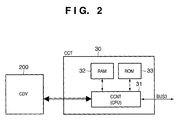
As shown in Fig. 2, the CCT 30 (card controller)
comprises a CCNT 31 (card control circuit) which
includes a CPU (central processing unit) for
controlling the entire CCT 30 (card controller) and
various control logic units, a RAM 32 from/in which a
desired program/data can be read out/written in
response to a request from the CPU or the like, and a
ROM 33 (an electrically erasable/programmable ROM may
be used instead) from which a control program/data and
the like used to implement interface control of the
entire CCT 30 (card controller), various kinds of
control that pertain to the CDV 200 (card device), and
the like are read out.
The CCNT 31 (card control circuit) comprises a
CPU for controlling the operation of the entire CCT 30
(card controller) in accordance with a control program
stored in the ROM 33/RAM 32, a system bus controller
for controlling address and data buses in the CCT 30
(card controller), an interrupt controller for
controlling interrupt requests from respective
controllers in the CCT 30 (card controller), a DMA
(direct memory access) controller for controlling
read/write of the RAM 32 and the respective controllers
at high speed without the intervention of the CPU in
response to requests from the respective controllers in
the CCT 30 (card controller), a timer controller which
can be used by the respective controllers in the CCT 30
(card controller), an external interface controller for
making data communications with the PCT 11 (printer
control circuit) via the interface bus BUS3, and a
device interface controller for detecting
attachment/detachment of the CDV 200 (card device), and
making data exchange and control with the CDV 200 (card
device).
The BUS3 can be an interface bus which can make
bidirectional communications to connect the PCT 11
(printer control circuit). For example, this
embodiment adopts an IEEE1284 compatible parallel
interface bus of an ECP mode (maximum transfer rate =
500 kbytes/sec) which allows two-way communications.
The data transfer rate of this bus is lower than the
aforementioned BUS1 and BUS2 but is high enough for the
data size the current CDV 200 (card device) processes.
Also, since the number of control logics that form the
interface controller and the control program scale can
be greatly reduced compared to USB and IEEE1394
mentioned above, a low-cost device can be currently
constructed using IEEE1284. Of course, when high data
transfer rate is required, a high-speed interface bus
such as aforementioned USB, IEEE1394, or the like can
be used.
The PWR 50 (power supply) controls ON/OFF of
various voltage outputs in accordance with the power
supply control signal CPW from the PCT 11 (printer
control circuit). For example, the PCT 11 (printer
control circuit) can turn on/off the power supply
output to be supplied to the CCT 30 (card controller)
in accordance with an instruction from CPW as needed.
The CDV 200 (card device) is a card device which
is physically detachable from the printer device 1, and
can undergo attachment/detachment detection, data
exchange control, and the like via the CCT 30 (card
controller) incorporated in the printer device 1. The
card device is an expandable, compact, lightweight,
portable device to which a communication means for
connecting the card device and an external device,
other control functions, and the like can be added in
addition to a storage means CMM (card device memory)
comprising a nonvolatile memory or the like.
This card device is also detachably attached to
digital devices such as a digital camera, digital video
camera, digital audio, personal computer, and the like,
and can store/save various data such as image data,
audio data, information, and the like acquired by these
devices.
As described above, in the image processing
system of the present invention, the aforementioned
card device, the CCT 30 (card controller) and PCT 11
(printer control circuit) incorporated in the printer
device 1, and the host device 1 can arbitrarily
exchange data with one another.
(Second Embodiment)
A case will be explained below with reference to
Fig. 3 wherein a communication function is added as an
expansion function to the CDV 200 (card device)
described in the above embodiment.
Since the arrangements of the host device 100 and
printer device 1 are the same as those described with
reference to Fig. 1, a detailed description thereof
will be omitted.
Reference numeral 200 denotes a CDV which
comprises a storage device CMM (card device memory)
comprising, e.g., a nonvolatile memory or the like, and
a WCT 210 (card device communication controller) which
exemplifies a communication function added as an
example of an expansion function, and makes wireless
communications with, e.g., external communication
devices 400. Note that an infrared communication (IrDA
or the like), radio wave communication, and the like
are available as wireless communication techniques. In
this embodiment, a communication scheme (BlueTooth
compatible) using a weak radio wave is adopted as the
wireless communication scheme.
The external communication devices 400 are
prepared as options by the user. For example, a WKB
410 (wireless keyboard input device), a WPDV 320
(wireless pointing device), and a WCP 440 (wireless
control panel) are prepared in place of the
aforementioned KB 310 (keyboard input device), PDV 320
(pointing device), and CP 130 (control panel), thus
reducing the total number of connection cables of the
entire system.
With this arrangement, since the number of
connection cables is reduced upon using the image
processing system in a living room in home, the
appearance of the room upon using the device can be
prevented from being spoiled, a sufficient operation
distance can be assured between the device and user,
the user never trips on the connection cord, and so
forth.
A CPH 430 (cellular phone) is a mobile
communication member such as a so-called portable
telephone, PHS, or the like. As is well known, in at
least the Japanese market, such devices have become
increasingly prevalent. In addition, additional
service functions such as an e-mail function, Internet
function, and the like have also prevailed since most
of these devices comprise character input/output means.
A wireless function (without using the public
network) is provided to such device so as to allow the
device to exchange data with the card device 200. For
example, e-mail messages received by the CPH 430
(cellular phone) from the public network, phonebook
data stored in the device, or the like are exchanged
with the printer device 1 or host device 100, so that
an e-mail message can be read, edited, or created on
the large screen of the DISP 140 (image input/output
device) connected to the host device, and such
information can be saved in the CPH 430 (cellular
phone) as data or can be printed by the printer device
1.
Furthermore, ten-key input operation, character
input operations using a ten-key pad, and the like of
the CPH 430 (cellular phone) can be used as input means
of other devices such as the printer device 1, host
device 100, and the like connected, or a display of the
CPH 430 (cellular phone) can be used as output means of
other devices such as the printer device 1, host device
100, and the like connected.
When a wireless communication function is
provided to other devices in addition to the
aforementioned device, data exchange with, e.g.,
digital home appliances and personal computer can be
made via the CDV 200 (card device). In this embodiment,
the wireless communication function has been
exemplified. Alternatively, an expansion function such
as a wired communication function, digital image
sensing device function, or the like can be added to
the CDV 200 (card device).
(Third Embodiment)
An arrangement in which the PCT 11 (printer
control circuit) described in the first and second
embodiments incorporates the CCNT 31 (card control
circuit) will be described below with reference to
Fig. 4.
Since the arrangements of the host device 100 and
CDV 200 (card device) in this embodiment are the same
as those described using Figs. 1 to 3, a detailed
description thereof will be omitted.
The CCT 30 (card controller) and printer
controller 10 in Figs. 1 to 3 are connected to each
other using a connector and the like, and their circuit
boards can be physically separated. For this reason,
the interface bus BUS3 is provided to independently
receive power supply from the PWR 50 (power supply),
and the two controllers are connected using a connector.
This arrangement is suitable for a case wherein
the user purchases and externally connects the CCT 30
(card controller) as an option after he or she
purchased the device. However, when the CCT 30 (card
controller) is mounted as a standard function of the
device from the beginning upon delivery, the cost
increases since a connector and a power supply circuit
for independently supplying electric power are required.
Also, in order to allow the user to attach the CCD 30
(card controller), a portion of the housing of the
printer device 1 must have a detachable mechanism,
resulting in an increase in cost.
In order to solve such cost problems, in this
embodiment, a control portion obtained by removing the
CPU and the interface controller of the interface bus
BUS3 from the CCNT 31 (card control circuit) shown in
Fig. 2 is built in as a CCNT 40 (card control circuit)
in the PCT 11 (printer control circuit).
Note that the PCT 11 (printer control circuit) of
this embodiment is a semiconductor device which is
prepared by physically forming, on a single chip, a bus
control circuit that allows the CCNT 40 (card control
circuit) to access the RAM 12 and ROM 13 and allows the
CPU to control the CCNT 40 (card control circuit) by
removing the interface controller for the interface bus
BUS3.
The contents of the RAM 32 and ROM 33 in the CCT
30 (card controller) described using Fig. 2 such as the
control programs/data that the CCNT 31 (card control
circuit) requires upon control are contained in the RAM
12 and ROM 13 in Fig. 4.
Furthermore, the aforementioned PWR 50 (power
supply) has an independent power supply line to the CCT
30 (card controller). However, since the CCT is
integrated in the arrangement of this embodiment, a PWR
55 (power supply) of this embodiment can reduce the
number of power supply lines.
With this arrangement, since the number of
components to be disposed on a control circuit board,
the area required for disposing such components, and
the like can be reduced, a lower-cost device can be
provided.
(Fourth Embodiment)
An arrangement in which most of controllers in
the printer controller 10 described in the third
embodiment are built in the PCT 11 (printer control
circuit) will be explained below with reference to
Fig. 5.
Since the arrangements of the host device 100 and
CDV 200 (card device) in this embodiment are the same
as those described using Figs. 1 to 4, a detailed
description thereof will be omitted.
In recent years, the semiconductor technique has
advanced rapidly, the wiring/gate layout in a
semiconductor can be made based on, e.g., 0.25-µ rule,
0.18-µ rule, or the like, and a semiconductor circuit
having a higher degree of integration than the
conventional circuit can be formed. Also, storage
devices such as a ROM, RAM, and the like with a
relatively large capacity, which are required upon
constructing a control circuit can be integrated in a
single semiconductor chip.
Such semiconductor technique can be applied to
the device of the present invention. Fig. 5 shows a
semiconductor device, which is obtained by physically
forming on a single chip, the RAM 12, ROM 13, and CCNT
40 (card control circuit) described in the third
embodiment, and a bus control circuit that allows the
CCNT 40 (card control circuit) to access the RAM 12 and
ROM 13 and allows the CPU to control the CCNT 40 (card
control circuit) by removing the interface controller
for the interface bus BUS3 described in the first and
second embodiments.
Furthermore, the aforementioned PWR 50 (power
supply) comprises an independent power supply line to
the CCT 30 (card controller). However, since the CCT
is integrated in this arrangement as in the fourth
embodiment, the PWR 55 (power supply) of this
embodiment can reduce the number of power supply lines.
With this arrangement, since the number of
components to be disposed on a control circuit board,
the area required for disposing such components, and
the like can be further reduced compared to the fourth
embodiment, a lower-cost device can be provided.
When the ROM 13 is not suitable for integration
on a single chip due to its program size or for the
convenience in the manufacture, the ROM 13 is excluded,
a bus signal line and the like used to access the ROM
outside the chip are provided, and an external ROM 13
can be used.
(Fifth Embodiment)
An arrangement in which the external interface
bus BUS2 of the host device 100, which is described in
the first to fourth embodiments, and is used to make
communications between the printer device 1 and host
device 100 is removed, and the external interface bus
BUS1 alone is used will be described below with
reference to Fig. 6.
A BUS in Fig. 6 has the same functions as those
of the BUS1, and can be a so-called external interface
bus which can make bidirectional communications to
connect the aforementioned EDV 170 (externally
connected device). For example, this embodiment adopts
an IEEE1394 compatible high-speed serial bus (maximum
transfer rate = 400 Mbits/sec). This bus can
simultaneously connect, via a hub, the option devices
300 such as the KB 310 (keyboard input device) used to
improve input operations of text and the like, a PDV
320 (pointing device) such as a mouse/touch pad or the
like used to easily instruct an input position/GUI
operation selection or the like, and the like, as in
the BUS1.
In this embodiment, the SCT 111 (system
controller) has an internal arrangement slightly
different from that in the first to fourth embodiments
described above.
Differences are that (1) the external interface
controller 2 for controlling the external interface bus
BUS2 that exchanges data with the printer device 1,
option devices 300, and the like is removed, (2) the
external interface controller 1 is changed to use the
aforementioned external interface bus BUS1 as the BUS
in Fig. 6, and to exchange data with the printer device,
option devices 300, and the like in addition to data
read/write with the EDV 170 (externally connected
device), (3) the external interface controller that
makes data communications with the host device 100 via
the external interface bus BUS2 explained in the PCT 11
(printer control circuit) of the printer device 1 is
replaced by an external interface controller that makes
data communications with the host device 100 via the
external interface bus BUS, and (4) the option devices
300 and the like are replaced by those which are
compatible to the interface specification of the BUS.
Such arrangement can be applied to the image
processing system of the present invention. According
to the arrangement of this embodiment, since the
external interface controller 2 is removed from the
host device, and an interface connector and the like
required to connect the BUS2 can also be removed, a
cost reduction of the whole device can be achieved.
Also, for a user who need not connect a plurality
of devices at the same time, since the connector of the
external interface adopted in this embodiment allows
easy insertion/removal, the need for even the hub can
be obviated if only a required device is connected to
the external interface bus BUS when necessary.
(Sixth Embodiment)
An arrangement in which the RTC 112 (real-time
clock) which is arranged in the system main controller
110 of the host device 100 described in the first to
fifth embodiments, and used to generate a time stamp
upon saving information such as a file or the like in a
memory, a timepiece/calendar function, and a print
start time is removed will be described below.
The RTC 112 (real-time clock) comprises a
secondary power supply such as a battery, and can
accurately measure time even when no electric power is
supplied to the host device. However, since a battery
is used, it is used up sometime or other, and must be
exchanged. Mainly in European countries, ecological
control (e.g., the user must detach a built-in battery
upon disposing a device) is projected to be applied.
As a measure to be taken against such control, a
mechanical structure that allows the user to detach a
battery for the RTC 112 (real-time clock) must be
adopted. When the user can detach the battery, he or
she may inadvertently detach the battery due to
erroneous operation or the like. If the battery is
detached, time information in the RTC 112 (real-time
clock) may not keep accurate time.
To solve this problem, in this embodiment, since
the host device 100 acquires a time casting or clock
signal from a public radio wave or time information
from a predetermined server which is connected to the
Internet/network and keeps standard time as needed, the
need for the RTC 112 (real-time clock) and its battery
is obviated.
The host device 100 may acquire time information
using given means at an appropriate timing, e.g., upon
starting up the system (upon power ON), and may manage
time using the internal timer controller, so that the
time information is used by the entire system. Also,
given means may occasionally acquire accurate standard
time at a required timing to generate a time stamp upon
saving/storing information such as a file or the like
in a memory. Furthermore, time information may be
acquired at the beginning of a print process and may be
supplied to the printer device 1. The printer device 1
may compare this time information with the previous
maintenance time to execute a cleaning process of a
print head as needed.
To achieve such function, the device must be
connected to the Internet or the like or to a device
that can receive a public radio wave. However, since,
for example, a home-use TV, a video recording/playback
device, or the like normally comprises a timepiece or
the like, time information can be acquired from such
device.
With the arrangement of this embodiment, as
described above, since the need for the RTC 112
(real-time clock) and its battery can be obviated
without degrading or omitting the time management
function, and the number of components and the area
required for mounting these components of the host
device 100 can be reduced, a cost reduction can be
achieved. Also, an ecological device which can cope
with the environmental problems mentioned above can be
provided.
(Seventh Embodiment)
The communication path among the respective units
described in the above embodiments will be explained
below. In the arrangement shown in Figs. 1 to 3,
information exchange is made in the path of host device
100 ↔ printer device 1 ↔ CCT 30 (card controller) ↔
CDV 200 (card device). That is, (1) the host device
100 communicates with the printer device 1 via the
external interface bus BUS2, (2) the printer device 1
communicates with the PCT 11 (printer control circuit)
and CCT 30 (card controller) via the external interface
bus BUS3, and (3) the CCT 30 (card controller) makes
attachment/detachment detection, data exchange control,
and communications with the device interface controller
provided in the CCT 30 (card controller) and the CDV
200 (card device), thus exchanging desired data.
In the arrangement shown in Figs. 4 and 5,
information exchange is made in the path of host device
100 ↔ printer device 1 ↔ CCNT 40 (card control
circuit) in PCT 11 (printer control circuit) ↔ CDV 200
(card device). That is, (4) the host device 100
communicates with the printer device 1 via the external
interface bus BUS2, (5) the printer device 1
communicates with the CCNT 40 (card control circuit)
via the internal bus of the PCT 11 (printer control
circuit), and (6) the CCNT 40 (card control circuit)
makes attachment/detachment detection, data exchange
control, and communications with the CDV 200 (card
device) via its internal device interface controller,
thus exchanging desired data.
In the arrangement shown in Fig. 6, items (1) and
(4) are replaced by "(7) the host device 100
communicates with the printer device 1 via the external
interface bus BUS", and other items (2), (3), (5), and
(6) remain the same.
Fig. 7 is a diagram for explaining the above
communication path, and arrows in Fig. 7 indicate data
exchange. From the left side in Fig. 7, "Host"
indicates a process in the host device 100 (S710).
"Communication controller" pointed by the arrow on the
right side of "Host" controls distribution of
transmission/reception data in the printer device 1,
and the arrow under "communication controller"
indicates a process for processing received data inside
the printer device 1 and printing out data upon
receiving a print-related command/data (S720).
"Card Controller" pointed by the arrow on the
left side of "communication controller" indicates a
process in the CCT 30 (card controller) or CCNT 40
(card control circuit (S730). "Card Device" pointed by
the arrow under "Card Controller" indicates a process
in the CDV 200 (card device) (S740). "Externally
connected device" pointed by the arrow under "Card
Device" indicates a process in external communication
devices 400 prepared as options by the user, as
described with reference to Fig. 3 (S750). For example,
this arrow indicates that information exchange can be
made with the WKB 410 (wireless keyboard input device),
WPDV 420 (wireless pointing device), WCP 440 (wireless
control panel), CPH 430 (cellular phone), and the like
via the CDV 200 (card device).
(Eighth Embodiment)
Communication information on the communication
path described in the above embodiment will be
explained below. Fig. 8 is a view for explaining the
format of the communication information.
In this embodiment, communications are made using
the packet format, and communication information can be
roughly classified into four types: (1) a PCMD packet
used to send a request associated with the print
function or the like to the printer device 1, (2) a
PSTR packet used to send various kinds of status
information associated with the print function of the
printer device 1, or information such as a return value
or the like associated with the print function, (3) a
CCMD packet used to send a request associated with
various functions of the CDV 200 (card device), and (4)
a CSTR packet used to send various kinds of status
information associated with the CDV 200 (card device)
or transmission information such as a return value or
the like.
Information in each packet will be explained
below. The PCMD packet contains an expansion code
"Esc" 1B (Hex) indicating a print function request at
the head position. Subsequently, a variable-length
character string "Cmd" which indicates a command that
expresses details of the request using a predetermined
character string follows. At the end of the packet,
variable-length data "Data" is data associated with the
command. "Data" is omitted depending on the type of
command, and if data are available, data associated
with the command are listed after 2-byte "length
information" (not shown) indicating the information
size in "Data". Note that "length information" of this
embodiment expresses the number of bytes using 16 bits,
in which the first byte designates lower 8 bits, and
the next byte designates upper 8 bits. A "length
information" value expresses the information size that
follows the "length information" in the number of bytes.
(PCMD packet example) Hex notation is 1B 5B 4B
02 00 41, 42, in which "Cmd" is 5B 4B, "Data" is 02 00
41 42, and "length information" indicates 2 bytes.
The PSTR packet contains "Len" which indicates
the number of bytes of "Str" at the head position.
Variable-length information "Str" represents various
kinds of status information associated with the print
function of the printer device or transmission
information such as a return value or the like
associated with the print value, and head information
is given by characters other than "Fs" 1C (Hex).
Note that "Len" of this embodiment expresses the
number of bytes using 2 bytes, in which the first byte
designates lower 8 bits, and the next byte designates
upper 8 bits. Furthermore, when the PSTR packet is
sent back to the card device controller, the first byte
value of "Len" is controlled not to assume 1C (Hex).
If the first byte of "Len" assumes 1C (Hex) in
association with the data length of "Str", 1 is added
to "Len", and dummy NULL data is appended to the end of
"Str". This is because the CCMD packet to be described
below starts from an expansion code "Fs" 1C (Hex). In
this way, the received data analysis process of the
card device controller is facilitated.
(PSTR packet example) In Hex notation 03 00 30
31 32, "Len" is 03 00, "Str" is 30 31 32, and "Len"
indicates 3 bytes.
The CCMD packet contains an expansion code "Fs"
1C (Hex) indicating a request that pertains to various
functions of the CDV 200 (card device) at the head
position. Then, 1-byte "N" indicating the request
source follows. For example, the host device can be
identified as the request source if "N" = "H"; or the
printer device if "N" = "P". Subsequently, a
variable-length character string "Cmd" which indicates
a command that expresses details of the request using a
predetermined character string follows. At the end of
the packet, variable-length data "Data" is data
associated with the command. "Data" is omitted
depending on the type of command, and if data are
available, data associated with the command are listed
after 2-byte "length information" (not shown)
indicating the information size in "Data".
Note that "length information" of this embodiment
expresses the number of bytes using 16 bits, in which
the first byte designates lower 8 bits, and the next
byte designates upper 8 bits. A "length information"
value expresses the information size that follows the
"length information" in the number of bytes.
(CCMD packet example) In Hex notation 1C 48 41
31 01 00 35, "N" is 48 (the host device is the request
source), "Cmd" is 41 31, "Data" is 01 00 35, and
"length information" indicates 1 byte.
The CSTR packet contains 2-byte "Len" indicating
the total number of bytes of "Fs", "N", and "Str" at
the head position. Subsequently, an expansion code
"Fs" 1C (Hex) that represents various kinds of status
information associated with the CDV 200 (card device)
or transmission information such as a return value or
the like follows. "Fs" is followed by 1-byte "N" which
indicates a destination. For example, the host device
can be identified as the destination if "N" = "H"; or
the printer device if "N" = "P". Variable-length
information "Str" indicates the contents of various
kinds of status information associated with the CDV 200
(card device) or transmission information such as a
return value or the like.
Note that "Len" of this embodiment expresses the
number of bytes using 16 bits, in which the first byte
designates lower 8 bits, and the next byte designates
upper 8 bits. Furthermore, the first byte of "Len" is
controlled not to assume 1B (Hex). If the first byte
of "Len" assumes 1B (Hex) in association with the data
length of "Str", 1 is added to "Len", and dummy NULL
data is appended to the end of "Str". This is because
the format of the PCMD and PSTR packets uses standard
specifications, and if addition of the CCMD and CSTR
packets changes the specifications, the compatibility
to the conventional format suffers.
(CSTR packet example) In Hex notation 05 00 1C
50 41 42 43, "Len" is 05 00, "N" is 50 (the printer
device is the destination), "Str" is 41 42 43, and
"Len" indicates 5 bytes.
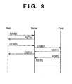
Communication control using the aforementioned
packets will be explained below with reference to
Fig. 9. Note that the vertical lines in Fig. 9
indicate communication points: "Host", "Printer", and
"Card" respectively indicate the host device 100, the
printer device 1, and the controller such as the CCT 30
(card controller) of the CDV 200 (card device) in turn
from the left side.
(1) The host device requests the printer device
to return status associated with the print function
using PCMD1 in the PCMD packet format.
(2) Upon receiving this packet, since the head
of the request packet is "Esc", the printer device
interprets that the packet is a print-related request,
and acquires internal status data of the printer to
generate status information. The printer device sends
back the status information to the host device using
PSTR1 in the PSTR packet format.
(3) The host device then requests using CCMD1 in
the CCMD packet format to return status associated with
the card device.
(4) Upon receiving this packet, since the head
of the request packet is "Fs", the printer device
interprets that the request is associated with the card
device, and transfers the received CCMD1 to the card
device controller such as the CCT 30 (card controller)
or the like via the aforementioned interface means.
(5) Since the head of the request packet is "Fs",
the card device controller interprets that packet, and
acquires the attachment state of the CDV 200 (card
device), status data of the card device, internal
status data of the card controller, and the like to
generate status information in response to the request
from the host device. The card device controller
copies the "N" identifier in the received packet CCMD1
to that in CSTR1 to be sent back so as to return status
information of the host device as the request source
using CSTR1 in the CSTR packet format, and sends the
CSTR1 packet to the printer device.
(6) Since the "N" identifier in CSTR1 sent from
the card device controller is "H", the printer device
transfers the CSTR1 packet to the host device. In this
way, the host device can acquire status information
from the card device controller via the printer device.
(7) The card device controller requests using
PCMD2 in the PCMD packet format the printer device to
return status associated with the print function.
(8) Upon receiving this packet, since the head
of the request packet is "Esc", the printer device
interprets that the packet is a print-related request,
and acquires internal status data of the printer to
generate status information. Since the request is
received from the card device controller using PCMD2,
the printer device sends back status information to the
card device controller using PSTR2 in the PSTR packet
format.
With the aforementioned communication control,
the host device can smoothly exchange data with the
card device via the printer device.
(Ninth Embodiment)
In the above embodiment, the communication
control at three communication points has been
explained. In such control method, as described in
Fig. 9, when the communication point as the request
source requires a reply from the request destination,
the request source must wait until the reply returns
from the request destination. If only the sequential
communication control shown in Fig. 9 is used, when the
communication control speed or the like among devices
is high enough even by making control for exclusively
using communications via the external interface bus
BUS2 and communications via the interface bus BUS3 or
the internal bus to the card control circuit CCNT in
the arrangement described using Figs. 1 to 6, the
arrangement of the eighth embodiment suffices, thus
simplifying the internal control circuit arrangement of
the printer.
Even when the communication control speed must be
increased, if the number of communication points is as
small as three, an increase in communication control
speed can be attained by controlling order management,
packet type discrimination, and the like for
intercommunications among devices without executing the
aforementioned exclusive control.
However, in order to exchange information even
with the external communication devices 400 (Fig. 3)
which are prepared by the user as options and include,
e.g., the WKB 410 (wireless keyboard input device),
WPDV 420 (wireless pointing device), WCP 440 (wireless
control panel), CPH 430 (cellular phone), and the like
via the CDV 200 (card device), and to systematically
use these devices on the system arrangement of the
present invention, difficulties in order management,
packet type discrimination, and the like for
intercommunications among devices, and a low
communication control speed are posed as technical
problems. In this embodiment, a control method that
allows smooth communication control among devices even
when a large number of devices are connected will be
explained below.
Fig. 10 is a view for explaining a packet used to
communicate with devices connected in this embodiment.
This packet is formed by seven fields, and functional
purposes of these fields will be explained below. Note
that fields "Len" to "Did2" have fixed lengths, and are
indispensable in all request/reply messages.
(1) The field "Len" indicates the data length of
the subsequent fields "Rn" to "Data/Str", and in this
embodiment, the data length is expressed by the number
of bytes using a 16-bit absolute value.
(2) The field "Rn" stores an identifier that the
request source can use as needed, and this field can
designate a request number. In this embodiment, the
request number is expressed by 8 bits. If the value in
this field is 0, it indicates that no request number is
used; if the value ranges from 1 to 255, it can be used
as the request number. Using the request number, the
order of replies to requests can be managed.
(3) The field "Msg" is an identifier that
roughly classifies the functions of request messages,
and has meanings in Table 1 below. In this embodiment,
the identifier is expressed by an 8-bit absolute value.
| Msg Field |
| Name | Value | Request Function |
| MsgPacketSize |
| | 0 | Packet size message |
| MsgDevConfig |
| | 1 | Read out device configuration information |
| MsgDevStatus |
| | 2 | Read out device status |
| MsgUI |
| | 3 | UI control |
| MsgFile |
| | 4 | File operation |
| MsgPrint |
| | 5 | Print function |
| MsgPrintText |
| | 6 | Simple print function |
| MsgCommand |
| | 7 | Expansion command |
| ... | ... | ... |
| Msgxxx | nnn | ... |
In Table 1, 1 ○ "MsgPacketSize" is a request with
which the request source makes the request destination
confirm if it can receive a given message packet size
before the source sends a packet with that size.
2 ○ "MsgDevConfig" requests to return Config
information (device configuration information) in Table
4 to be described later.
3 ○ "MsgDevStatus" requests to return Status
information (device status information) in Table 5 to
be described later, and can designate required detailed
status items in the field "Data" using a character
string in a list format of parameters which are
specified by predetermined reserved words.
4 ○ "MsgUI" requests a function that pertains to
UI (user interface (operation)) resources together with
a UI control command in Table 6 (to be described later)
in the field "Data".
5 ○ "MsgFile" requests a function that pertains to
file operation together with a File control command in
Table 8 (to be described later) in the field "Data".
6 ○ "MsgPrint" requests all print-related
functions.
7 ○ "MsgPrintText" requests a function that
pertains to a simple print process that can be done by
the printer device alone without the intervention of
the host device.
8 ○ "MsgCommand" requests a function that pertains
to expansion commands except for those described above.
(4) The field "Ack" contains information used to
inform the presence/absence of a reply to a request
message or OK/NG discrimination in a reply message, as
shown in Table 2 below, and in this embodiment,
information is expressed by an 8-bit absolute value.
| Ack Field |
| Name | Value | Request Function |
| AckNoReply |
| | 0 | Reply not required |
| AckWaitReply | 1 | Reply required |
| AckReplyOk | 2 | Reply message OK |
| AckReplyNg |
| | 3 | Reply message NG |
| ... | ... | ... |
| Ackxxx | Nnn | ... |
In Table 2, 1 ○ "AckNoReply" instructs that
no reply to a request message is required.
2 ○ "AckWaitReply" instructs that a reply to a
request message is required.
3 ○ "AckReplyOk" expresses return of a reply
message to a message which is instructed by
"AckWaitReply".
4 ○ "AckReplyNg" expresses a state wherein a reply
message to a message which is instructed by
"AckWaitReply" cannot be returned, or some error has
occurred with respect to a request message. Also,
AckNoReply and AckWaitReply indicate request messages,
and AckReplyOk and AckReplyNg are reply messages.
(5) The field "Did1" expresses the device type
of the request source, and in this embodiment, the
device type is represented by an 8-bit absolute value.
See Table 3 for device types.
(6) The field "Did2" expresses the device type
of the request destination, and in this embodiment, the
device type is represented by an 8-bit absolute value.
See Table 3 for device types. Note that a reply
message is returned from a device indicated by Did2 to
a device indicated by Did1. In such case, the contents
of Did1 and Did2 are not replaced.
| Device Type (Did1/Did2 Field) |
| Name | Value | Target Device |
| DevSys |
| | 0 | Host device 100 |
| DevPrt | 1 | Printer Device 1 |
| DevCct | 2 | Card controller CCT 30 |
| DevCp | 3 | Control panel CP 130 |
| DevDisp | 4 | Image input/output device DISP 140 |
| DevAud | 5 | Audio input/output device AUD 140 |
| DevEmm | 6 | External memory EMM 180 |
| DevKb | 7 | Keyboard input device KB 310 |
| DevPdv | 8 | Pointing device input device PDV 320 |
| DevWkb | 9 | Wireless keyboard WKB 410 |
| DevWpdv | 10 | Wireless pointing device WPDV 420 |
| DevWcp | 11 | Wireless control panel WCP 440 |
| DevDscm | 12 | Digital camera |
| DevDvcm |
| | 13 | Digital video camera |
| DevDaud |
| | 14 | Digital audio |
| DevCph |
| | 15 | Cellular phone CPH 430 |
| DevCdv | 16 | Card device CDV 200 |
| DevCmm | 17 | Card device memory |
| ... | ... | ... |
| Devxxx | nnn | ... |
Intercommunications can be made among devices
listed in Table 3, and the numbers for identifying
device types are assigned for respective devices.
Note that the aforementioned devices themselves
need not always physically comprise the aforementioned
control means. For example, devices, which are
directly connected to the host device 100 alone and
cannot directly communicate with other devices in the
arrangement described using Figs. 1 to 6, e.g., DevCp
(control panel CP 130), DevDisp (image input/output
device DISP 140), DevAud (audio input/output device AUD
140), DevEmm (external memory EMM 180), need not
individually comprise the communication control circuit
and control means of the present invention. Those
devices need only be controlled by the host device 100
by emulation or the like implemented by the control
program or the like of the host device 100, so that
these devices can be seen from externally connected
devices upon communication control.
In this way, a cost reduction of the entire
device can be achieved. Likewise, the printer device 1
can alternately execute communication control of
devices such as DevCct (card controller CCT 30), DevCdv
(card device CDV 200), DevCmm (card device memory), and
the like. Of course, the aforementioned communication
control means may be prepared in the card controller
CCT 30 to execute communication control of devices such
as DevCdv (card device CDV 200), DevCmm (card device
memory), and the like. Also, the printer device 1,
DevCct (card controller CCT 30), or DevCdv (card device
CDV 200) can execute communication control of external
devices such as DevWkb (wireless keyboard WKB 410),
DevWpdv (wireless pointing device WPDV 420), DevWcp
(wireless control panel WCP 440), and the like.
(7) The field "Data/Str" contains
variable-length data used to exchange a detailed
function instruction associated with a function
instructed in the Msg field or additional information
such as status information or the like. This field
serves as a Data field that designates a parameter of a
detailed command or the like of the request function in
a request message, and as an Str field that returns a
parameter such as a return value to a request in a
reply message.
For example, 1 ○ when the Msg field indicates the
MsgPacketSize request, this field instructs the packet
size value.
2 ○ A reply message to the MsgDevConfig request
returns Config information in Table 4 below.
3 ○ A reply message to the MsgDevStatus request
returns Status information in Table 5 below.
4 ○ When the Msg field indicates the MsgUI request,
this field instructs a UI control command in Table 6
below, and UI information or the like in Table 7 below
as needed.
5 ○ A reply message to the MsgUI returns UI
information or the like in Table 7 below.
6 ○ When the Msg field indicates the MsgFile
request, this field instructs a File control command in
Table 8 below, and the file name/write data or the like
as needed.
7 ○ A reply message to the MsgFile request returns
a File control command in Table 8 below, and the file
name/read data or the like as needed.
8 ○ When the Msg field indicates the MsgPrint
request, this field instructs print control information.
9 ○ When the Msg field indicates the MsgPrintText
request, this field instructs simple print control
information.
When the Msg field indicates the MsgCommand
request, this field instructs expansion function
control information.
The contents shown in Table 4 are stored in a
ROM/RAM as storage means for respective devices, and
form an information set used to inform another device
of the device confirmation. 1 ○ "Device information"
indicates a device type, and is 8-bit numerical value
information corresponding to the device type in Table 3.
2 ○ "Device name" is character string information
which expresses the device type and ends with NULL 00
(Hex), and can designate a maximum of 255 characters.
3 ○ "Device genre information" is a 16-bit
identification code that identifies the device genre,
and is used to identify genres such as a printer device,
digital home appliance, and the like.
4 ○ "Device basic function information" is 16-bit
flag information which identifies basic functions that
the device can provide. One basic function is assigned
to one bit position, and the presence/absence of that
basic function is indicated by a bit value (1/0) at
that position. For example, this information can be
used to identify the presence/absence of basic
functions such as a print function, file function,
wireless function, and the like.
5 ○ "Device function specification information" is
16-bit flag information which indicates function
specifications associated with basic functions with bit
values "1" in the "device basic function information",
and flag information is assigned to each basic function.
For example, when a given device has a print function,
this information can be used to identify if a color
print function, ink remaining amount detection function,
and the like are available.
6 ○ "Device control version information" is a
16-bit identification code which indicates the version
of a control program in the device.
7 ○ "Device control ROM information is a 32-bit
identification code, which includes information
indicating if the control program in the device is
rewritable, the type of storage medium, storage medium
size, the number of rewrite times, and the like.
8 ○ "Device communication control information" is
a 32-bit identification code, which represents the
external interface type of the device, interface
specification version information of each type, and
interface performance such as the maximum transfer rate
and the like.
The contents shown in Table 5 are stored in a RAM
as storage means for each device, and form an
information set which informs another device of device
status. 1 ○ "Basic status information" is 16-bit flag
information that identifies basic device status. A
status item is assigned to each bit, and basic status
is indicated by a bit value (1/0) at that position.
For example, in case of the printer device, this
information can be used to identify basic status, e.g.,
if the printer is ready or busy, if any errors have
occurred, if detailed status information is present, if
error history information is present, and so forth.
2 ○ "Detailed status information" is character
string information which expresses requested detailed
device status by a character string in the list format
and ends with NULL 00 (Hex), and can designate a
maximum of 255 characters. When the information size
exceeds 255 characters, this information is sent back
while being segmented into a plurality of reply packets.
3 ○ "Error history information" is character
string information which expresses error history
information, if it is available, by a character string
in the list format and ends with NULL 00 (Hex), and can
designate a maximum of 255 characters. When the
information size exceeds 255 characters, this
information is sent back while being segmented into a
plurality of reply packets.
| UI Control Command |
| Name | Value | Request Function |
| UiConfig |
| | 0 | Read out UI configuration |
| UiSelect |
| | 1 | Reserve UI to be used |
| UiRead | 3 | Inform UI input information in use |
| UiWrite |
| | 4 | Inform UI output information in use |
Table 6 summarizes UI control commands each of
which instructs a detailed function of a UI control
request when the contents of the Msg field are MsgUI,
and this command is set at the head of the Data field.
1 ○ The "UiConfig" command requests to return
configuration information of input operation/display
output resources of the user interface (UI). In this
case, after the UiConfig command, a resource item
(input operation/display output) to be acquired is
designated in the Data field using a character string
in the list format of parameters specified by
predetermined reserved words or the like. In case of a
reply message, after the UiConfig command, a UI
information item in Table 7 below is returned in the
Str field using a character string in the list format
of parameters specified by predetermined reserved words
or the like.
2 ○ The "UiSelect" command requests use
(reservation) of user interface resources. In this
case, after the UiSelect command, a user request item
of an input operation/display output resource to be
used is designated in the Data field using a character
string in the list format of parameters specified by
predetermined reserved words or the like. Also, an
event message that automatically informs detection of
input operation, use of which has been reserved by the
parameters, can also be designated. Upon detection of
input operation, a reply message containing the UiRead
command is returned.
3 ○ The "UiRead" command requests to return input
operation resource status designated in advance by the
UiSelect command. In this case, after the UiRead
command, a detection request item of a target input
operation resource can be designated in the Data field
using a character string in the list format of
parameters specified by predetermined reserved words or
the like. Also, upon detection of input operation, the
event message of which has been designated by the
UiSelect command, this reply message is sent back.
4 ○ The "UiWrite" command requests a display
output operation resource designated in advance by the
UiSelect command to make desired display. In this case,
after the UiWrite command, an output item to a display
output resource to be used (information such as
ON/OFF/flickering, and flickering period if the target
resource is an LED indicator; buzzing frequency/buzzing
start·stop/buzzing duration, the number of times,
rhythm, and the like if the target resource is a
buzzer; audio output item/audio data, and the like if
the target resource is an audio output; or display
item/display character string, code page, color, size,
and the like if the target resource is a text display)
is designated in the Data field using a character
string in the list format of parameters specified by
predetermined reserved words or the like acquired by
the UiConfig command.
Table 7 summarizes the configuration information
of input operation/display output resources requested
by the Msg field = MsgUI and the UiConfig command, and
is stored in a ROM/RAM as storage means for each device.
1 ○ "UI input resource information" is information of
input operation resources of a given device. This
information expresses the input operation function type
such as operation buttons, a keyboard, a ten-key pad,
cursor keys, a joystick, or the like, various kinds of
detectable operation event type information such as
button input operation, key input operation, button
depression, button release, key inputs, and the like of
each of cursor keys, and the like, and usable
conditions of each input resource indicating if that
resource can be used, can be occupied, can be shared,
and so forth, using a character string in the list
format of parameters specified by predetermined
reserved words.
2 ○ "UI output resource information" is the
configuration information of display and audio output
resources of a given device, that are associated with
operation. This information expresses information of
items that can be instructed (e.g., ON/OFF/flickering,
and flickering period if the output resource is an LED
indicator; buzzing frequency/buzzing start·stop/buzzing
duration, the number of times, rhythm, and the like if
the output resource is a buzzer; audio output
item/audio data, and the like if the output resource is
an audio output; or display item/display character
string, code page, color, size, and the like if the
output resource is a text display), and usable
conditions of each output resource indicating if that
resource can be used, can be occupied, can be shared,
and so forth, using a character string in the list
format of parameters specified by predetermined
reserved words.
| File Control Command |
| Name | Value | Request Function |
| FileInfo |
| | 0 | File information |
| FileOpen |
| | 1 | Open file |
| FileClose |
| | 2 | Close file |
| FileCreate | 3 | Create new file |
| FileDelete |
| | 4 | Delete file |
| FileSeek |
| | 5 | Change file operation position |
| FileRead |
| | 6 | Read out file |
| FileWrite |
| | 7 | Write file |
| FileFormat |
| | 8 | Format |
| ... | ... | ... |
| Filexxx | Nnn | ... |
Table 8 summarizes File control commands each of
which instructs the detailed function of a file
operation request when the contents of the Msg field
indicate MsgFile, and this command is set at the head
of the Data field. 1 ○ The "FileInfo" command is a
reply request of file information associated with File
operation. After the FileInfo command, a request
information item is designated in the Data field using
a character string in the list format of parameters
specified by predetermined reserved words or the like.
In case of a reply message, after the FileInfo command,
file information (e.g., file directory information),
file attribute information of designated file
information or the like (e.g., file name, data type,
file size, modification information (read only, erase
permitted/inhibited, copy permitted/inhibited, the
presence/absence of visibility from the user, the
presence/absence of password protection, and the like),
free space size, and the like) are returned in the Str
field using a character string in the list format of
parameters specified by predetermined reserved words in
correspondence with a request item.
2 ○ The "FileOpen" command requests to open a file
prior to read/write access of a desired file. After
the FileOpen command, the file name to be opened,
password information, and the like are designated in
the Data field using a character string in the list
format of parameters specified by predetermined
reserved words. In case of a reply message, after the
FileOpen Command, a 16-bit value (if the value is more
than 0, it indicates successful file open operation; if
it is 0, it indicates unsuccessful file open operation)
indicating the file handle number used to access the
opened file, a 32-bit value indicating a file access
position (file pointer), and target file attribute
information (e.g., file name, data type, file size,
modification information (read only, erase
permitted/inhibited, copy permitted/inhibited, the
presence/absence of visibility from the user, the
presence/absence of password protection, and the like),
free space size, and the like) are returned in the Str
field using a character string in the list format of
parameters specified by predetermined reserved words.
3 ○ The "FileClose" command requests to close a
file upon completion of read/write access of desired
file contents. After the FileClose command, a 16-bit
value indicating the file handle number to be closed is
designated in the Data field. In case of a reply
message, after the FileClose command, a 16-bit value
indicating the requested file handle number,
success/failure information of file close operation,
and target file attribute information (e.g., file name,
data type, file size, modification information (read
only, erase permitted/inhibited, copy
permitted/inhibited, the presence/absence of visibility
from the user, the presence/absence of password
protection, and the like), free space size, and the
like) are returned in the Str field using a character
string in the list format of parameters specified by
predetermined reserved words.
4 ○ The "FileCreate" command requests to create a
new file prior to read/write access of a desired new
file. After the FileCreate command, the file name to
be created, data type, modification information,
password information, and the like are designated in
the Data field using a character string in the list
format of parameters specified by predetermined
reserved words. In case of a reply message, after the
FileCreate command, a 16-bit value (if the value is
more than 0, it indicates successful file open
operation; if it is 0, it indicates unsuccessful file
open operation) indicating the file handle number used
to access the opened file, and target file attribute
information (e.g., file name, data type, file size,
modification information (read only, erase
permitted/inhibited, copy permitted/inhibited, the
presence/absence of visibility from the user, the
presence/absence of password protection, and the like),
free space size, and the like) are returned in the Str
field using a character string in the list format of
parameters specified by predetermined reserved words.
5 ○ The "FileDelete" command requests to delete a
desired file. After the FileDelete command, the file
name to be deleted, password information, and the like
are designated in the Data field using a character
string in the list format of parameters specified by
predetermined reserved words. In case of a reply
message, success/failure information of file delete
operation, and target file attribute information (e.g.,
file name, data type, file size, modification
information (read only, erase permitted/inhibited, copy
permitted/inhibited, the presence/absence of visibility
from the user, the presence/absence of password
protection, and the like), free space size, and the
like) are returned in the Str field using a character
string in the list format of parameters specified by
predetermined reserved words.
6 ○ The "FileSeek" command requests to designate
the read/write position (file pointer) of a desired
file. After the FileSeek Command, a 16-bit value
indicating the file handle number to be accessed, and a
32-bit value indicating the target file access position
(file pointer) are designated in the Data field. In
case of a reply message, after the FileSeek command, a
16-bit value indicating the requested file handle
number, a 32-bit value indicating the updated file
access position (file pointer), success/failure
information of requested access, and target file
attribute information (e.g., file name, data type, file
size, modification information (read only, erase
permitted/inhibited, copy permitted/inhibited, the
presence/absence of visibility from the user, the
presence/absence of password protection, and the like),
free space size, and the like) are returned in the Str
field using a character string in the list format of
parameters specified by predetermined reserved words.
7 ○ The "FileRead" command requests to read out
from a desired file. After the FileRead command, a
16-bit value indicating the file handle number to be
accessed, and a 16-bit value indicating the target read
size are designated in the Data field. In case of a
reply message, after the FileRead command, a 16-bit
value indicating the requested file handle number, a
32-bit value indicating the updated file access
position (file pointer), and a 16-bit value indicating
the actual read size are returned in the Str field.
8 ○ The "FileWrite" command is a write request in
a desired file. After the FileWrite command, a 16-bit
value indicating the file handle number to be accessed,
a 16-bit value indicating the target write size, and
data to be written in the file are designated in the
Data field. In case of a reply command, a 16-bit value
indicating the requested file handle number, a 32-bit
value indicating the updated file access position (file
pointer), and a 16-bit value indicating the actual
write completion size are returned in the Str field.
9 ○ The "FileFormat" command requests to
initialize (completely erase) the file system of a
device. After the FileFormat command, the volume name,
password, and the like are designated in the Data field
using a character string in a list format of parameters
specified by predetermined reserved words or the like.
In case of a reply message, after the FileFormat
command, success/failure information of file format,
the created volume name, free space size information,
and the like are returned in the Str field using a
character string in a list format of parameters
specified by predetermined reserved words or the like.
Communication control using the aforementioned
packet format in Fig. 10 will be explained below with
reference to Fig. 11. Note that the vertical lines in
Fig. 11 indicate communication points, and Devxxx
indicates the device type explained using Table 3:
"DevSys", "DevPrt", "DevCct", and "DevCph" in turn from
the left side respectively exemplify the host device
100, printer device 1, the controller such as the CCT
30 (card controller) of the CDV 200 (card device), and
the CPH 430 (cellular phone) as one of external devices
connected via the WCT (card device communication
controller) which is provided on the CDV 200 (card
device) and makes wireless communications. In Fig. 11,
MsgX(A) and MsgX(N) are request messages, and MsgX(R)
is a reply message to MsgX(A) (X = 1 to 7).
In the following description, [MsgVVV, AckWWW,
DevXXX, DevYYY, Z...Z] indicates the packet contents of
a message, and the Msg, Ack, Did1, Did2, and Data/Str
fields in Fig. 10 respectively contain MsgVVV, AckWWW,
DevXXX, DevYYY, and a detailed command or reply
parameter having contents Z...Z.
(1) When the CDV 200 (card device) is inserted
in a card device insert port of the printer device,
DevCct (card controller) sends a request message
Msg1(A) [MsgCommand, AckWaitReply, DevCct, DevSys, card
device attachment message] packet to the PCT 11
(printer control circuit) via the interface or internal
bus so as to inform DevSys (host device) of insertion
of the card device.
Since the Ack field is AckWaitReply and the Did2
field is DevSys, the printer controller transfers this
packet to the host device. Since the Ack field is
AckWaitReply and the Did2 field is DevSys, i.e., since
that request is addressed to the host device, the host
device interprets the packet contents, and recognizes
that the card device has been attached.
(2) Since the Ack field is AckWaitReply, the
host device sends a reply message Msg1(R) [MsgCommand,
AckReplyOk, DevCct, DevSys, card device attachment
message] packet to the printer device via the external
interface to return that packet to the request source
(DevCct (card controller)). Since the Ack field is
AckReplyOk and the Did1 field is DevCct, the printer
device transfers that packet to DevCct (card
controller) via the interface or internal bus. Since
the Ack field is AckReplyOk, DevCct (card controller)
determines that the host device can correctly recognize
attachment of the card device.
(3) The host device sends a request message
Msg2(A) [MsgDevStatus, AckWaitReply, DevSys, DevCct,
card device type message] packet to be sent to DevCct
(card controller) to the printer device via the
external interface so as to acquire the attached card
device type. Since the Ack field is AckWaitReply and
the Did2 field is DevCct, the printer device transfers
this packet to DevCct (card controller) via the
interface or internal bus.
(4) The host device then sends a request message
Msg3(A) [MsgDevStatus, AckWaitReply, DevSys, DevPrt,
detailed status information (host requires)] packet to
the printer device via the external interface so as to
acquire the printer device status.
(5) DevCct (card controller) checks the card
device to generate card device type information in
accordance with the request in (3). Since the Ack
field of the request message is AckWaitReply, DevCct
sends a reply message Msg2(R) [MsgDevStatus, AckReplyOk,
DevSys, DevCct, card device type information] packet to
the printer device via the interface or internal bus so
as to return that message to the host device as the
request source. Since the Ack field is AckReplyOk and
the Did1 field is DevSys, the printer device transfers
the packet to the host device via the external
interface. Since the Ack field is AckReplyOk and the
Did1 field is DevSys, i.e., since that reply is
addressed to the host device, the host device
interprets the packet contents. As a result, the host
device can normally recognize the type of card device
attached.
(6) The printer device generates requested
detailed status information in accordance with the
request in (4). Since the Ack field of the request
message is AckWaitReply, the printer device sends a
reply message Msg3(R) [MsgDevStatus, AckReplyOk, DevSys,
DevPrt, (requested) detailed status information] packet
to the host device as the request source via the
external interface. Since the Ack field is AckReplyOk
and the Did1 field is DevSys, i.e., since the reply is
addressed to the host device, the host device
interprets the packet contents. As a result, the host
device can normally recognize the printer device status.
(7) The host device sends a request message
Msg4(A) [MsgFile, AckWaitReply, DevSys, DevCct,
FileInfo (file information message)] packet to be sent
to DevCct (card controller) to the printer device via
the external interface so as to acquire file
information on the card device. Since the Ack field is
AckWaitReply and the Did2 field is DevCct, the printer
device transfers that packet to DevCct (card
controller) via the interface or internal bus.
(8) When the user turns on the power switch of
the CPH 430 (cellular phone), the wireless
communication controller of the CPH 430 (cellular
phone) informs the wireless communication controller on
the CDV 200 (card device) of that message. Upon
receiving this message, the card device also informs
DevCct (card controller) of that message. Since DevCct
(card controller) controls packet communications in
place of the cellular phone, it sends a request message
Msg5(A) [MsgCommand, AckWaitReply, DevCph, DevSys,
cellular phone connection message] packet to the PCT 11
(printer control circuit) via the interface or internal
bus so as to inform the host device of connection of
the cellular phone. Since the Ack field is
AckWaitReply and the Did2 field is DevSys, the printer
controller transfers this packet to the host device via
the external interface. Since the Ack field is
AckWaitReply and the Did2 field is DevSys, i.e., since
that request is addressed to the host device, the host
device interprets the packet contents, and recognizes
that the cellular phone has been connected.
(9) DevCct (card controller) reads out file
information on the card device in accordance with the
request in (7). Since the Ack field of the request
message is AckWaitReply, DevCct sends a reply message
Msg4(R) [MsgFile, AckReplyOk, DevSys, DevCct, FileInfo
(file information)] packet to the printer device via
the interface or internal bus so as to return that
reply to the host device as the request source. Since
the Ack field is AckReplyOk and the Did1 field is
DevSys, the printer device transfers that packet to the
host device via the external interface.
Since the Ack field is AckReplyOk and the Did1
field is DevSys, i.e., since that reply is addressed to
the host device, the host device interprets the packet
contents. As a result, the host device can normally
recognize file information on the card device.
(10) The printer device sends a request message
Msg6(A) [MsgUI, AckWaitReply, DevPrt, DevDisp, UiConfig,
output resource alone message] packet to the host
device via the external interface so as to acquire
output resource information of the display DIS 140 of
the host device as a preliminary process for outputting
a message or the like to the display of the host device.
(11) Since the Ack field of the request in (8)
is AckWaitReply, the host device sends a reply message
Msg5(R) [MsgCommand, AckReplyOk, DevCph, DevSys,
cellular phone connection message] packet to the
printer device via the external interface so as to
return that reply to the request source DevCph
(cellular phone). Since the Ack field is AckReplyOk
and the Did1 field is DevCph, the printer device
transfers the packet to DevCct (card controller) via
the interface or internal bus. Since the Ack field is
AckReplyOk and the Did1 field is DevCph, and DevCct
(card controller) controls packet communications in
place of the cellular phone (although that packet is
addressed to the cellular phone), it interprets the
packet contents, and grants the radio communication
controller on the CDV 200 (card device) and cellular
phone permission to connect (if necessary).
(12) Since the host device executes packet
communication control of the DISP 140, and the Ack
field in the request in (10) is AckWaitReply, it sends
a reply message Msg6(R) [MsgUI, AckReplyOk, DevPrt,
DevDisp, UiConfig, output resource information] packet
to the printer device via the external interface. As a
result, the printer device can acquire the
configuration information of the display resources of
the host device.
(13) In order to make the printer device print
out the file information acquired in (9), the host
device sends a request message Msg7(N) [MsgPrint,
AckNoReply, DevSys, DevPrt, print control command]
packet to the printer device via the external interface.
The printer device starts the requested print operation.
Since the Ack field is AckNoReply, no reply message is
returned.
With the aforementioned communication control,
even when a large number of devices are connected,
smooth communication control can be done among devices.
(10th Embodiment)
A request message interpretation control program
using the packet format described using Fig. 10 is
shown in Fig. 12, and will be explained below. Note
that this control program is stored in storage means of
respective devices such as a RAM in the STC 111 (system
controller) of the host device 100, the ROM 13 of the
printer device 1, the ROM 33 in the card device
controller CCT 30, and the like. This embodiment will
explain details of request message interpretation
control of devices DevSys (host device 100) DevPrt
(printer device 1), DevCct (card controller CCT 30),
DevCp (control panel CP 130), DevDisp (image
input/output device DISP 140), DevAud (audio
input/output device AUD 140), DevEmm (external memory
EMM 180), DevKb (keyboard input device KB 310), and
DevPdv (pointing device input device PDV 320) described
in Table 3. Note that the host device 100 of this
embodiment corresponds to seven different devices
DevSys, DevCp, DevDisp, DevAud, DevEmm, DevKb, and
DevPdv, and comprises seven sets of process 1 to be
described below.
Process 1 shown in Fig. 12 is a request message
interpretation control program process which starts
when each device type receives a request message to the
self device. That is, when the Ack field of a packet
is AckNoReply or AckWaitReply, and the Did2 field is
the self device type, the request contents in the Msg
field described using Table 1 are interpreted, and
processing steps S1 to S13 corresponding to
MsgPacketSize to MsgCommand requests described in Table
1 are executed.
(1) If the Msg field contains MsgPacketSize, it
is checked in step S1 if the packet size requested in
the Data field can be received. If the requested
packet size can be received, a reply message is sent
back to the Did1 device while setting AckReplyOk in the
Ack field and the requested packet size in the Str
field. On the other hand, if the request packet size
cannot be received, a reply message is sent back to the
Did1 device while setting AckReplyNg in the Ack field
and the receivable packet size in the Str field.
(2) If the Msg field contains MsgDevConfig, a
reply message in which AckReplyOk is set in the Ack
field and Config information in Table 4 is set in the
Str field is sent back to the Did1 device in step S2.
(3) If the Msg field contains MsgDevStatus, and
if the request contents include no errors, a reply
message in which AckReplyOk is set in the Ack field,
and basic status information in Table 5 and detailed
status information of an item designated by the Data
field are set in the Str field is sent back to the Did1
device in step S3. If the request contents include an
error, a reply message in which AckReplyNg is set in
the Ack field, and basic status information in Table 5,
and an extracted error of a parameter designated by the
Data field are set in the Str field is sent back to the
Did1 device.
(4) If the Msg field contains MsgUI and the Data
field starts from UiConfig in Table 6, and if the
request contents include no errors, a reply message in
which AckReplyOk is set in the Ack field, and one of
input operation resource configuration information
alone/output resource configuration information
alone/input and output resource configuration
information of user interface resources of the self
device described using Table 6 is set in the Str field
in correspondence with the request in the Data field is
sent back to the Did1 device in step S4. If the
request contents include an error, a reply message in
which AckReplyNg is set in the Ack field and an
extracted error of a parameter designated by the Data
field is set in the Str field is sent back to the Did1
device.
(5) If the Msg field contains MsgUI and the Data
field starts from UiSelect in Table 6, and if the
request contents include no errors, it is checked in
step S5 if a resource corresponding to the use request
in the Data field can be used. If the resource can be
used, it is stored as operation resource use management
information to indicate that the requested input
operation or output resource is reserved by the device
type of Did1. In addition, a reply message in which
AckReplyOk is set in the Ack field and information of
the input/output operation resource which is granted
permission to use is set in the Str field is sent back
to the Did1 device. If the resource cannot be used, a
reply message in which AckReplyNg is set in the Ack
field and information of the input/output operation
resource which cannot be used is set in the Str field
is sent back to the Did1 device. If the request
includes an error, a reply message in which AckReplyNg
is set in the Ack field and an extracted error of a
parameter designated by the Data field is set in the
Str field is sent back to the Did1 device. Furthermore,
if input operation designated with an event message in
the request is granted permission to use, when that
operation is detected later, a predetermined reply
message (MsgUI + UiRead) indicating detection of the
operation can be automatically sent to the Did1 device.
(6) If the Msg field contains MsgUI and the Data
field starts from UiRead in Table 6, if the request
contents include no errors, and if the request item is
registered in the operation resource management
information stored by the UiSelect command in (4), a
reply message in which AckReplyOk is set in the Ack
field and the status of the input operation resource
requested by the Data field is set in the Str field is
sent back to the Did1 device in step S6. If the
request includes an error, or if the request item is
not contained in the operation resource management
information, a reply message in which AckReplyNg is set
in the Ack field and an extracted error of a parameter
designated by the Data field is set in the Str field is
sent back to the Did1 device.
(7) If the Msg field contains MsgUI and the Data
field starts from UiWrite in Table 6, if the request
contents include no errors, and if the request item is
registered in the operation resource management
information stored by the UiSelect command in (4),
display or audio output according to an item requested
by the Data field is made, and a reply data set with
AckReplyOk in the Ack field is sent back to the Did1
device in step S7. If the request includes an error,
or if the request item is not contained in the
operation resource management information, a reply
message in which AckReplyNg is set in the Ack field and
an extracted error of a parameter designated by the
Data field is set in the Str field is sent back to the
Did1 device.
(8) If the Msg field contains MsgFile and the
Data field starts from FileInfo in Table 8, a reply
message is sent back to the Did1 device in step S8. In
this message, AckReplyOk is set in the Ack field, and
information corresponding to a request item described
in 1 ○ in Table 8 in the Data field, e.g., file
directory information, or file attribute information of
designated file information or the like (e.g., file
name, data type, file size, modification information
(read only, erase permitted/inhibited, copy
permitted/inhibited, the presence/absence of visibility
from the user, the presence/absence of password
protection, and the like), free space size, and the
like) is set in the Str field.
If the request includes an error, a reply message
in which AckReplyNg is set in the Ack field and an
extracted error of a parameter designated by the Data
field is set in the Str field is sent back to the Did1
device.
(9) If the Msg field contains MsgFile and the
Data field starts from one of FileOpen to FileWrite in
Table 8, and if the request contents include no errors,
a reply message in which AckReplyOk is set in the Ack
field and information associated with file access upon
executing a file access process described in 2 ○ to 8 ○ in
Table 8 in accordance with the request in the Data
field is set in the Str field is sent back to the Did1
device in step S9.
If the request includes an error, a reply message
in which AckReplyNg is set in the Ack field, and an
extracted error of a parameter designated by the Data
field is set in the Str field is sent back to the Did1
device.
(10) If the Msg field contains MsgFile and the
Data field starts from FileFormat in Table 8, and if
the request contents include no errors, a reply message
in which AckReplyOk is set in the Ack field and
information associated with a format process upon
executing a file format process described in 9 ○ in
Table 8 in accordance with the request in the Data
field is set in the Str field is sent back to the Did1
device in step S10. If the request includes an error,
a reply message in which AckReplyNg is set in the Ack
field and an extracted error of a parameter designated
by the Data field is set in the Str field is sent back
to the Did1 device.
(11) If the Msg field contains MsgPrint, and if
the request contents include no errors, a print
operation is executed in accordance with the request in
step S11. If the request operation is successfully
done, and if the Ack field of the request message is
AckWaitReply, a response message set with AckReplyOk in
the Ack field is sent back to the Did1 device. On the
other hand, if the request operation is not
successfully done, and if the Ack field of the request
message is AckWaitReply, a reply message in which
AckReplyNg is set in the Ack field and operation error
information is set in the Str field is sent back to the
Did1 device.
If the request contents include an error, and if
the Ack field of the request message is AckWaitReply, a
reply message in which AckReplyNg is set in the Ack
field and an extracted error of a parameter designated
by the Data field is set in the Str field is sent back
to the Did1 device.
(12) If the Msg field contains MsgPrintText, and
if the request contents include no errors, a simple
print operation is executed according to the request in
step S12. If the request operation is successfully
done, and if the Ack field of the request message is
AckWaitReply, a response message set with AckReplyOk in
the Ack field is sent back to the Did1 device. On the
other hand, if the request operation is not
successfully done, and if the Ack field of the request
message is AckWaitReply, a reply message in which
AckReplyNg is set in the Ack field and operation error
information is set in the Str field is sent back to the
Did1 device. If the request contents include an error,
and if the Ack field of the request message is
AckWaitReply, a reply message in which AckReplyNg is
set in the Ack field and an extracted error of a
parameter designated by the Data field is set in the
Str field is sent back to the Did1 device.
(13) If the Msg field contains MsgCommand, and
if the request contents include no errors, an expansion
function according to the request is executed in step
S13. If the request operation is successfully done,
and if the Ack field of the request message is
AckWaitReply, a response message set with AckReplyOk in
the Ack field is sent back to the Did1 device. On the
other hand, if the request operation is not
successfully done, and if the Ack field of the request
message is AckWaitReply, a reply message in which
AckReplyNg is set in the Ack field and operation error
information is set in the Str field is sent back to the
Did1 device. If the request contents include an error,
and if the Ack field of the request message is
AckWaitReply, a reply message in which AckReplyNg is
set in the Ack field, and an extracted error of a
parameter designated by the Data field is set in the
Str field is sent back to the Did1 device.
In each of the processes (steps S1 to S13), if
the device itself does not support the requested
function (e.g., DevPrt does not support MsgFile
function), a reply message in which AckReplyNg is set
in the Ack field and parameters requested by the Data
field are set in the Str field is sent back to the Did1
device. If the Ack field of the request message is
AckNoReply, no such reply is returned basically.
However, if the purpose of the requested function is
attained by only returning information, e.g., the
request MsgPacketSize, MsgDevConfig, MsgDevStatus,
UiConfig of MsgUI, UiRead of MsgUI, and the like is
received, the aforementioned reply is returned even
when AckNoReply is designated.
(11th Embodiment)
Examples of control programs that can be applied
to the arrangement of the first to 10th embodiments
mentioned above will be explained in detail below with
reference to the flow charts.
Process 2 in Fig. 13 is one of control programs
of the card controller CCT 30 or card control circuit
CCNT 40. The program is stored in the ROM 33 of the
card controller CCT 30 or the ROM 13 of the printer
controller 10, and objective control can be implemented
when the CPU reads out and executes the program at an
appropriate timing as needed.
This control program is executed when the card
device CDV 200 is inserted in the card device insert
port of the printer device 1 and the card controller
CCT 30 or card control circuit CCNT 40 recognizes
attachment of the card device by an interrupt signal or
the like.
The type of card device CDV 200 attached is read
out in step S20, and card device connection message
information such as hardware configuration information
or the like of the attached card device is generated in
step S21. In process 9 to be described later, the card
device connection message information is sent to the
host device 100 via the interface or internal bus and
the printer device 1, thus ending this control program.
Process 3 in Fig. 14 is also one of control
programs of the card controller CCT 30 or card control
circuit CCNT 40. The program is stored in the ROM 33
of the card controller CCT 30 or the ROM 13 of the
printer controller 10, and objective control can be
implemented when the CPU reads out and executes the
program at an appropriate timing as needed.
This control program is a control program example,
which is executed when the card device CDV 200 is
inserted in the card device insert port of the printer
device 1 and the card controller CCT 30 or card control
circuit CCNT 40 recognizes attachment of the card
device by an interrupt signal or the like, or when an
external communication device such as the CPH 430
(cellular phone) or the like is connected via the card
device communication controller of the card device 200,
and which allows the card controller to use an
indicator such as an LED or the like of the printer
device 1 and display output of the DISP 140 of the host
device using the MsgUI request described in the ninth
embodiment.
In step S40, the LED indicator of the printer
device 1 (DevPrt device) is controlled to flicker so as
to inform the user that device connection confirmation
of the card device, cellular phone, or the like is in
progress. In step S41, a message or an image such as
an icon or the like which informs the user that device
connection confirmation is in progress is displayed on
the display output device DISP 140 (DevDisp device) of
the host device, or a voice message indicating that
device connection confirmation is in progress is output
from the audio output device AUD 140 (DevAud device).
In step S42, an objective process, for example, process
2 mentioned above if the card device is connected, a
device connection confirmation procedure if an external
communication device such as the CPH 430 (cellular
phone) or the like is connected, or the like is
executed.
Upon completion of the objective process, LED
flickering of the printer device that has started in
step S41 is stopped in step S43, and the message
displayed in step S41 is cleared, a message indicating
completion of the device connection procedure is
displayed for a predetermined period of time, or a
voice message indicating completion of the device
connection procedure is output in step S44. In step
S45, the message or the like displayed in step S44 is
cleared, thus ending this control program.
Process 4 in Fig. 15 is one of control programs
of the host device. This control program is loaded
from the read-only storage device (RDV) of the host
device onto the RAM of the system controller (SCT) as
needed or is pre-stored in the ROM or the like, and
objective control can be implemented when the CPU reads
out and executes the program at an appropriate timing
as needed.
This control program is a control program example
which is executed when the host device makes file
access to the card device CDV 200 attached to the
printer device 1, and which allows the host device to
use an indicator such as an LED or the like of the
printer device 1 using the MsgUI request described in
the ninth embodiment.
In step S60, the LED indicator of the printer
device 1 (DevPrt device) is controlled to flicker so as
to inform the user that the card device is being
accessed. In step S61, target file access to a memory
in the card device, e.g., file read/write access or the
like, is made. Upon completion of such objective
process, LED flickering of the printer device that has
started in step S60 is stopped in step S62, thus ending
this control program.
Process 5 in Fig. 16 is also one of control
programs of the host device. This control program is
loaded from the read-only storage device (RDV) of the
host device onto the RAM of the system controller (SCT)
as needed or is pre-stored in the ROM or the like, and
objective control can be implemented when the CPU reads
out and executes the program at an appropriate timing
as needed.
This control program is a control program example
executed when the host device shifts to a power saving
mode by user operation or after no operation is made
for a predetermined period of time or more.
In step S80, a transition request to the power
saving mode is sent to the devices connected such as
the printer device 1 and the like using a predetermined
command and the like. In step S81, the control waits
until all request destination devices have shifted to
the power saving mode. After it is confirmed that all
request destination devices have shifted to the power
saving mode, the host device itself shifts to the power
saving mode in step S82, thus ending this control
program.
Lastly, process 6 in Fig. 17 is also one of
control programs of the host device. This control
program is loaded from the read-only storage device
(RDV) of the host device onto the RAM of the system
controller (SCT) as needed or is pre-stored in the ROM
or the like, and objective control can be implemented
when the CPU reads out and executes the program at an
appropriate timing as needed.
This control program is a control program example
which allows the host device to acquire a character
input from the keyboard input device (KB 310), wireless
keyboard input device (WKB 410), cellular phone (CPH
430), or the like connected.
In step S100, a usable keyboard input device
connected to the system is checked and confirmed, and
if at least one usable keyboard input device is found,
an input operation resource use request is issued to
the found keyboard input device and the control waits
for a use permission message from the request
destination in step S101. The flow then advances to
step S102.
If no usable keyboard input device is found as a
result of step S100, the flow jumps to step S102
without issuing any input operation resource use
request in step S101. In step S102, another device
which comprises a usable ten-key input device and is
connected to the system, e.g., the cellular phone (CPH
430) or the like, is checked and confirmed. If at
least one usable device is found, an operation resource
use request of, e.g., a ten-key input operation, a
character input operation using a ten-key operation, or
the like is issued, and the control waits for a use
permission message from the request destination in step
S103. The flow then advances to step S104. If no
useable device is found as a result of step S102, the
flow jumps to step S104 without issuing any input
operation resource use request in step S103.
In step S104, the control waits for a character
input from the device designated by the use request,
and if a character input is detected, input character
information or the like is provided to an application
program or the like that requires the character input.
If an input device is found in neither of steps S100
and S102, a character input function by means of at
least conventional character input means (for example,
51 hiragana letters, 52 alphabetical letters (capital
and small letters), numerals, symbols, and the like are
selectively displayed on the DISP 140 as the display
output device of the host device by select operations
using cursor keys/buttons on the control panel (CP 130),
and characters are input by repeating character
select/determine operations using cursor keys/buttons
on the control panel (CP 130)) is provided in step S104.
When character input operation is complete, this
control program ends.
As described above, resources such as input
operation means, LED indicators, text/image output
devices, and the like of devices connected to the
system can be used by another device as needed, and the
status data of connected devices can be acquired by
another device as needed. By utilizing such functions,
the need for adding indicators such as LED indicators,
operation buttons, and the like for the purpose of
improving operability of the device can be obviated or
minimized. Also, when the display device and audio
output device of the host device are used, an image
processing system with high operability that can be
easily understood and used even by a beginner using
color display, icons, visual and audible messages, and
the like can be provided. In the aforementioned
control program examples, an example wherein the
printer device uses input/output resources of other
devices has not been explained. For example, when an
error such as out of print sheets or the like has
occurred during a print process in the printer, a
message "Printer is out of sheets!" may be displayed
using the display of the cellular phone connected.
(12th Embodiment)
Control program examples associated with error
processes, which can be applied to the arrangements of
the first to 10th embodiments will be described in
detail below with reference to the flow charts.
When the printer device of the system cannot
communicate with the host device, for example, when the
power switch of the host device is OFF or when an
interface cable that connects the printer and host
devices is not connected, even when the user inserts a
card device into the printer device, the card
controller CCT 30 and the printer device cannot
communicate with the host device. In such state, the
function of automatically detecting attachment of the
card device by the host device cannot be provided.
Such problems are mainly caused by careless
operations of a user "who does not turn on the power
switch of the host device or does not connect an
interface cable", and troubleshooting of such problems
is taken care of in the column of "helpless reasons in
some sense" in operation manuals. However, since most
of users of the home-use system that the present
invention provides are beginners, it is important for
the sake of high operability to inform solutions of
such careless operations, which are possibly simplest
and easiest to understand without requiring the users
to read manuals.
Hence, this embodiment will explain (1) "a method
of at least informing the user of operation errors
using the indicator/buzzer or the like of the printer
device when the host device issues a request associated
with the card device to the printer device but the
printer device cannot communicate with the card device",
(2) "a method of at least informing the user of
operation errors using the indicator/buzzer or the like
of the printer device when the printer device cannot
communicate with the host device", and (3) "a method in
which when the printer device cannot communicate with
the host device, it stores requests or the like to the
host device caused by user operations as an error
history, and when the host and printer devices can
communicate with each other later, the host device
reads out the error history from the printer device,
interprets the contents and order of erroneous
operations, and offers operation guides by means of
text, icons, voice messages, and the like on the
screen", in a state wherein at least the printer device
receives power supply.
Process 7 of Fig. 18 is a flow chart for
explaining the control program of method (1). Note
that this control program is one of control programs of
the printer device. The program is stored in the ROM
13 of the printer controller 10 in the printer device,
and objective control can be implemented when the CPU
reads out and executes the program at an appropriate
timing as needed.
This control program is a reception control
program executed when the host device sends request
information to the printer device 1 via the external
interface.
It is checked in step S120 by the means explained
in the eighth or ninth embodiment if information
received from the host device is a request for, e.g., a
print function or the like of the printer device. If
YES in step S120, conventional print operation control
or the like of the printer device is executed in step
S121, and this control program ends.
On the other hand, if it is determined in step
S120 that the input information is a request associated
with card control, it is checked in step S122 if a card
device is attached. If YES in step S122, the request
information from the host device is transferred to the
card controller CCT 30 or card control circuit CCNT 40
via the interface or internal bus in step S123, thus
ending this control program. On the other hand, if it
is determined in step S122 that no card device is
attached, the LED of the printer device is turned on or
flickered, or its buffer (if available) is driven to
inform the user that an operation error has occurred,
and an error termination message of the request is sent
to the host device via the external interface in step
S124, thus ending this control program.
Process 8 of Fig. 19 is a flow chart for
explaining a control program of methods (2) and (3).
Note that this control program is one of control
programs of the printer device. The program is stored
in the ROM 13 of the printer controller 10 in the
printer device, and objective control can be
implemented when the CPU reads out and executes the
program at an appropriate timing as needed.
This control program is a reception control
program executed when the card controller CCT 30 or
card control circuit CCNT 40 sends request information
or the like to the printer device 1 via the interface
or internal bus by user operation associated with the
card device 200 or user operation at an externally
connected device that can communicate with the card
device communication controller 210 of the card device
200.
It is checked in step S140 by the means explained
in the eighth or ninth embodiment if information
received from the card controller CCT 30 or card
control circuit CCNT 40 via the interface or internal
bus is request information for a print function or the
like of the printer device. If YES in step S140,
conventional print operation control or the like of the
printer device is executed in step S141, and this
control program ends.
On the other hand, if it is determined in step
S140 that the input information is a request associated
with card control, it is checked in step S142 if the
printer device can communicate with the host device.
If YES in step S142, the request information from the
card controller CCT 30 or card control circuit CCNT 40
is transferred to the host device via the external
interface, thus ending this control program.
However, if it is determined in step S142 that
the printer device cannot communicate with the host
device, it is checked in step S144 if an error history
can be recorded or need not be recorded. If an error
history cannot be recorded or need not be recorded, in
step S145 the LED of the printer device is turned on or
flickered, or its buffer (if available) is driven to
inform the user that an operation error has occurred.
Furthermore, an error termination message of the
request is sent to the card controller CCT 30 or card
control circuit CCNT 40 via the interface or internal
bus, thus ending this control program.
On the other hand, if an error history can be
recorded in step S144, the request information from the
card controller CCT 30 or card control circuit CCNT 40
is recorded as error history information in the RAM 12,
a nonvolatile memory, or the like in step S146, and a
message indicating that "the request information cannot
be sent to the host device and is stored in an error
history" is sent to the card controller CCT 30 or CCNT
40 via the interface or internal bus in step S147, thus
ending the control program. To promptly inform the
user of an operation error, "a process for turning on
or flickering the LED or the printer device or driving
the buzzer (if available)" to inform the user that an
operation error has occurred can be added to step S147.
Note that the error history information recorded in
step S146 can use only part of the received request
information. That is, information that allows the host
device to determine only the operation error sequence
upon analyzing the error history information later
suffices.
Process 9 of Fig. 20 is a flow chart for
explaining a control program of methods (2) and (3),
which is different from process 8. Note that this
control program is one of control programs of the card
controller CCT 30 or card control circuit CCNT 40. The
program is stored in the ROM 33 in the card controller
or the ROM 13 of the printer controller 10, and
objective control can be implemented when the CPU reads
out and executes the program at an appropriate timing
as needed.
This control program is a transmission control
program executed when the card controller CCT 30 or
card control circuit CCNT 40 sends request information
or the like to the printer device 1 via the interface
or internal bus by user operation associated with the
card device 200 or user operation at an externally
connected device that can communicate with the card
device communication controller 210 of the card device
200.
It is checked in step S160 if the printer device
can communicate with the host device. If YES in step
S160, the request information is sent from the card
controller CCT 30 or card control circuit CCNT 40 to
the host device via the printer device in step S161,
thus ending this control program.
However, if it is determined in step S160 that
the printer device cannot communicate with the host
device, it is checked in step S162 if an error history
can be recorded or need not be recorded. If an error
history cannot or need not be recorded, a "request for
turning on or flickering the LED or the printer device
or driving the buzzer (if available)" is issued via the
interface or internal bus to inform the user that an
operation error has occurred in step S163, thus ending
this control program.
On the other hand, if an error history can be
recorded in step S162, the request information which is
scheduled to be sent is recoded in the RAM 32 (or the
RAM 12 in the arrangement of Figs. 4 and 5), a
nonvolatile memory, or the like as error history
information in step S164, and a message indicating that
"request information cannot be sent to the host device
and is recorded in the error history" is sent to the
card controller CCT 30 or CCNT 40 in step S165, thus
ending this control program.
To promptly inform the user of an operation error,
"a process for requesting to turn on or flicker the LED
or the printer device or to drive the buzzer (if
available)" to inform the user that an operation error
has occurred can be added to step S165. Note that the
error history information recorded in step S164 can use
only part of the received request information. That is,
information that allows the host device to determine
only the operation error sequence upon analyzing the
error history information later suffices.
Lastly, process 10 of Fig. 21 is a flow chart for
explaining a control program of method (3). Note that
this control program is loaded from the read-only
storage device (RDV) of the host device onto the RAM of
the system controller (SCT) as needed or is pre-stored
in the ROM or the like, and objective control can be
implemented when the CPU reads out and executes the
program at an appropriate timing as needed.
This control program is an error operation guide
control program executed when the host device
recognizes connection with the printer device and is
ready to communicate.
It is checked in step S180 by acquiring status of
the printer apparatus or card controller if error
history information stored in step S146 in process 8 or
step S164 in process 9 is present. If NO in step S180,
another normal process is executed (step S181). On the
other hand, if error history information is present,
the error history information is read out from the
printer device or card controller in step S182, and the
display output device DISP 140, audio output device AUD
140, or the like is controlled to make an output that
at least indicates that an operation error has occurred
so as to inform the user of the operation error in step
S183. In step S184, the error history information is
analyzed to output an operation guide by means of text,
icons, voice message, or the like which explain the
operation sequence in correspondence with the order
errors occurred and causes of the errors using the
display output device DISP 140, audio output device AUD
140, or the like. If the user cancels the operation
guide by predetermined operation or the like, this
control program ends.
For example, when the contents of the error
history information are 1 ○ a card device attachment
message, an operation guide message like "Turn on the
power switch of the device main body. Then set the
card in the printer." can be output.
(13th Embodiment)
Control program examples associated with print
control, which can be applied to the arrangements of
the aforementioned embodiments, will be described in
detail below with reference to the flow charts.
Process 11 of Fig. 22 is a flow chart for
explaining a control program associated with print
control of the printer device.
Note that this control program is one of control
programs of the printer device. The program is stored
in the ROM 13 of the printer controller 10 in the
printer device, and objective control can be
implemented when the CPU reads out and executes the
program at an appropriate timing as needed.
This control program is a reception control
program executed when the card controller CCT 30 or
card control circuit CCNT 40 sends a request or the
like to the printer device 1 via the interface or
internal bus by user operation associated with the card
device 200 or user operation at an externally connected
device that can communicate with the card device
communication controller 210 of the card device 200.
It is checked in step S200 by the means explained
in the eighth or ninth embodiment if information
received from the card controller CCT 30 or card
control circuit CCNT 40 via the interface or internal
bus is request information for a print function. If
YES in step S200, it is checked in step S201 if the
printer device is in a sleep state such as the power
saving mode or the like. If YES in step S201, and if
the mechanism of the printer unit PU 20 of the printer
device must be initialized, a printer initial operation
is started in step S202 to prepare for a print process
so that a print operation which starts in response to a
print request from the host device to the printer
device or a simple print operation in which the printer
alone can print like the MsgPrintText request explained
in the above embodiment can start as early as possible.
The flow then advances to step S204.
On the other hand, if the printer device is not
in a sleep state in step S201, since the printer has
already completed an initial operation and the like and
is ready to print anytime, and the printer initial
operation in step S202 is not required, the flow jumps
to step S204. It is checked in step S204 if the
request information pertains to a simple print function
in which the printer alone can print like the
MsgPrintText request. If YES in step S204, a simple
print process such as text print or the like is
executed in accordance with the request information in
step S206, thus ending this control program.
On the other hand, if the request is a normal
print request via the host device in step S204, the
request information is transferred to the host device
via the external interface in step S205, thus ending
this control program. Also, if the request information
is other than the print function in step S200, since
the printer device need not be ready to print in step
S202 even when the printer device is in a sleep state
such as the power saving mode or the like, the request
information is similarly transferred to the host device
in step S205, thus ending this control program. Note
that the control for transferring the request
information to the host device in step S205 can use
process 8 in Fig. 19.
Process 12 of Fig. 23 is one of control programs
of the card controller CCT 30 or card control circuit
CCNT 40. This control program is stored in the ROM 33
of the card controller CCT 30 or the ROM 13 of the
printer controller 10, and objective control can be
implemented when the CPU reads out and executes the
program at an appropriate timing as needed.
This control program is a print control program
example of the card controller, which is associated
with a function of printing data on the card device or
printing a received mail message requested by an
externally connected device such as a cellular phone or
the like while the card device CDV 200 is attached or
an externally connected device such as the CPH 430
(cellular phone) or the like is connected via the card
device communication controller of the card device 200.
Note that this control program is launched when
text print or the like is instructed by predetermined
operation.
In step S220, the print performance of the
printer device 1 is checked by the aforementioned
device configuration/device status read means or the
like to acquire, from the printer device, information
indicating if the printer device has font information
such as CG or the like, if the printer has an emulation
function, and so forth. If desired print information
is made up of simple image/text information alone, and
the printer has image/text print functions of such
information, it is determined that the print process
can be done by the printer alone, and print control is
made using print control information (e.g., using the
aforementioned MsgPrintText request message) that
allows the printer alone to print in step S222. On the
other hand, if desired print information contains a
high-quality image or the like, and cannot be printed
by only the functions of the printer, a print process
is done by passing data required for the print process
to the host device via the printer device, and sending
print control information that controls the printer to
print a desired image from the host device to the
printer device in step S221.
Process 13 of Fig. 24 is a flow chart for
explaining a control program associated with
communication control of the printer device described
in the arrangement of the eighth embodiment. Note that
this control program is one of control programs of the
printer device, the program is stored in the ROM 13 of
the printer controller 10 in the printer device, and
objective control can be implemented when the CPU reads
out and executes the program at an appropriate timing
as needed.
This control program is a communication control
program that exclusively controls the external
interface bus BUS2 which connects the host device and
printer device, and interface bus BUS3 that connects
the printer controller in the printer device and the
card controller especially in the system arrangement
shown in Figs. 1 to 3.
Upon receiving large-size request information
such as print control information or the like from the
host device via the external interface bus BUS2, this
control program is launched. It is checked in step
S240 if communications on the interface bus BUS3 have
already been restricted in step S241. If YES in step
S240, the flow jumps to step S242. On the other hand,
if communications are not restricted, communication
control restriction of the interface bus BUS3 that
connects the card controller and printer controller
starts in step S241.
Note that restriction may simply set the
interface bus BUS3 in a busy state to physically
inhibit communications with the card controller, or may
control the card controller to retard large-size data
communications when the protocol means or the like
between the card controller and printer controller
declares that the printer device is communicating with
the host device.
In step S242, a print process or the like starts
in response to a request such as print control
information received from the host device. It is
checked in step S243 if print control that requires
large-size request information such as print control
information or the like from the host device is
complete (e.g., completion of a print job). If NO in
step S243, restriction continues, and the flow jumps to
step S245. If the print control is complete,
communication restriction of the interface bus BUS3
that connects the card controller and printer
controller is canceled to allow normal communications
in step S244, and the flow advances to step S245. In
step S245, other required conventional processes such
as a post process and the like are executed, and this
control program ends.
As described above, while large-size data is
transferred via one interface bus, communications on
the other interface bus are temporarily restricted. In
this way, since the printer controller can restrict
data communications from the card controller during the
print operation from the host device, the printer can
concentrate on control associated with the print
operation. With this arrangement, since the circuit
arrangement of the printer controller can be simplified,
and the processing performance of the CPU can be
suppressed, a cost reduction of the whole device can be
achieved.
If the card device has, e.g. only a memory
function, the application function using the card
device controls in the following sequence: 1 ○ the host
device reads out file information or the like on the
card device; and 2 ○ the host device generates print
control information from the file information and
controls the printer apparatus to print. Hence, even
when the arrangement of this embodiment is adopted, the
performance of the system never drops.
(14th Embodiment)
Device control program examples that can be
applied to the arrangements of the aforementioned
embodiments will be explained in detail below with
reference to the flow charts.
Processes 14 and 15 of Fig. 25 correspond to one
of control programs of the host device. This control
program is loaded from the read-only storage device
(RDV) of the host device onto the RAM of the system
controller (SCT) as needed or is pre-stored in the ROM
or the like, and objective control can be implemented
when the CPU reads out and executes the program at an
appropriate timing as needed.
This control program is a management control
program of device control which allows the host device
to use devices connected to the system.
This control program is launched when the system
of the host device is started up or an application
program is launched. In step S260, all detachable,
usable devices connected to the system are recognized.
If a newly connected device is found, a device control
program of the found device is searched for and read
out in the following sequence, and is stored in the RAM
or the like of the STC 111 (system controller) in the
host device or device connection management information
is updated in step S261. In the search/read sequence
of the device control program, if the RDV (read-only
storage device) of the host device is ready to be read,
the RDV is searched, and if an appropriate control
program is found, the search ends. On the other hand,
if the RDV is not ready to be read (e.g., no storage
medium is set in the RDV), or if no appropriate program
is found from the RDV as a result of the search, the
EMM (expansion memory) is searched. If an appropriate
program is found, the search ends.
Furthermore, if no EMM is attached, or if no
program is found as a result of the search, it is
checked if the target connected device stores a control
program. If a control program is found, the search
ends. If no program is found even after that search,
it is checked if the device is connected to the
Internet/network. If the device is connected to the
Internet/network, a predetermined external server is
searched. If an appropriate program is found, the
search ends.
If the device is not connected to the
Internet/network, or if no appropriate program is found
from the external server as a result of the search,
storage means of other devices connected to the system
are searched. If an appropriate program is found, the
search ends.
If no appropriate program is found even after the
aforementioned search processes, it is determined that
no program is found, and the search ends. If a target
device control program is found as a result of the
search, the device control program is read out from the
location where it was found. If no program is found,
the target device is disabled.
If another newly connected device is found in
step S260, the device driver search/read process is
executed again, and the device connection management
information is updated in step S261. Upon completion
of recognition of all devices connected, the flow
advances to process 15.
In process 15, matching between device control
programs of connected devices and a target device
control program are checked in step S262. If all
connected devices match the respective device control
programs, the flow jumps to step S269 to enable all
connected devices, thus ending this control program.
If a mismatch connected device is detected in step S262,
and if the corresponding control program of the device
is not rewritable, a search result "not found" is set
in step S263, and the flow advances to step S264. On
the other hand, if the control program is rewritable,
an optimal control program is searched for.
Upon searching, it is checked first if the target
connected device stores a control program. If a
control program is found, the search ends. If no
program is found, and if the RDV (read-only storage
device) of the host device is ready to be read, the RDV
is searched. If an appropriate control program is
found, the search ends.
On the other hand, if the RDV is not ready to be
read (e.g., no storage medium is set in the RDV), or if
no appropriate program is found from the RDV as a
result of the search, the EMM (expansion memory) is
searched. If an appropriate program is found, the
search ends. Furthermore, if no EMM is attached, or if
no program is found as a result of the search, it is
checked if the device is connected to the
Internet/network. If the device is connected to the
Internet/network, a predetermined external server is
searched. If an appropriate program is found, the
search ends.
If the device is not connected to the
Internet/network, or if no appropriate program is found
from the external server as a result of the search,
storage means of other devices connected to the system
are searched. If an appropriate program is found, the
search ends. If no appropriate program is found even
after the aforementioned search processes, it is
determined that no program is found, and the search
ends.
In step S246, the search result in step S263 is
checked. If the search result is "not found", the
target device is disabled, and an error message
indicating this is displayed on the screen or the like
in step S268, thus ending this processing. On the
other hand, if an appropriate control program can be
found, the current control program information is read
out from the target device and is stored in a
nonvolatile memory such as the EMM or the like as
needed in step S265.
Note that the control program information can be
stored in all other devices which are connected to the
system and comprise nonvolatile storage means that can
store and rewrite their contents, e.g., a card device,
an external storage device connected on the
Internet/network, and the like. In step S266, the
optimal control program is read out from the location
where that program was found as a result of the search.
In step S267, the control program of the target device
is rewritten by the optimal control program. In step
S269, only matching connected devices are set as usable
devices, and this processing ends. Note that an alert
message "Program updating of connected device is in
progress. Do not shut down power supply!" may be
displayed on the display in steps S265 to S267.
Process 16 of Fig. 26 is one of control programs
of the host device. This control program is loaded
from the read-only storage device (RDV) of the host
device onto the RAM of the system controller (SCT) as
needed or is pre-stored in the ROM or the like, and
objective control can be implemented when the CPU reads
out and executes the program at an appropriate timing
as needed.
This control program is a management control
program of device control which allows the host device
to enable devices connected to the system.
This control program is launched when the system
of the host device is started up or an application
program is launched. In step S280, available device
information is acquired from process 14 described above.
In step S281, devices required for an application
program to be launched are extracted with reference to
management information such as header information or
the like recorded on the same recording medium as the
application program to be launched. It is checked in
step S282 if at least one of the devices extracted in
step S281 are connected. If none of devices required
for the application program are connected, an error
message (for example, when the application to be
launched requires a device card, a message "Set card in
printer") is output in step S285.
On the other hand, if even at least one of the
required devices is connected in step S282, and at
least one of functions that the application program
provides is available using only the connected device,
the selected application program is launched in step
S283, and an application program process is executed in
step S284.
Process 17 of Fig. 27 is one of control programs
of the card controller CCT 30 or card control circuit
CCNT 40. The program is stored in the ROM 33 of the
card controller CCT 30 or the ROM 13 of the printer
controller 10, and objective control can be implemented
when the CPU reads out and executes the program at an
appropriate timing as needed.
This control program is a matching control
program between the card device and card controller,
which is executed when the card device CDV 200 is
attached, and the card controller CCT 30 or card
control circuit CCNT 40 recognizes attachment of the
card device.
Function version information of the card device
is acquired in step S290, and is compared with that of
the card controller stored in the ROM 33 of the card
controller CCT 30 or the ROM 13 of the printer
controller 10 in step S291. If compatibility/matching
upon function control is found, the card device is
enabled in step S294, and a card device connection
message or the like is sent to the host device, thus
ending this processing.
On the other hand, if no compatibility/matching
is found in step S291, it is checked in step S292 if
control program information for the card controller
having compatibility/matching such as addition of new
functions is present on the card device. If such
program information is found, the control program
information on the card device is read out to partially
or entirely rewrite the control program stored in the
ROM 33 of the card controller CCT 30 or the ROM 13 of
the printer controller 10 in step S293. In step S294,
the card device is enabled, and a card device
connection message or the like is sent to the host
device, thus ending this processing.
If no control program information for the card
controller having compatibility/matching such as
addition of new functions is present on the card device
in step S292, a request is issued to the host device to
make it rewrite the control program of the card
controller under the control like in process 15 in step
S295. If the host device can successfully update the
control program having compatibility/matching with the
card device in step S296, the card device is enabled,
and a card device connection message or the like is
sent to the host device in step S294, thus ending this
processing.
On the other hand, if the host device cannot
update the control program either in step S296, the
connected card device is disabled, and a card device
incompatible message or the like is sent to the host
device in step S297. Upon receiving this message, the
host device can output an error message such as an
alert message "This card cannot be used. Please
contact the card manufacturer." on the display or the
like.
With the aforementioned control of this
embodiment, the need for installation processes and the
like can be obviated upon using devices connected to
the system. Expandable devices such as the card device
and the like may have advanced functions by updating
them. However, at the time of delivery of a printer
device that can receive the card device to the user, it
is difficult to provide full compatibility to every
card devices that will come into existence in the near
future by expecting all such advanced functions. This
embodiment can flexibly solve such problem, and the
user can use functionally upgraded card devices without
any installation processes.
That is, if the card device itself has
functionally upgraded control program information of
the card controller with compatibility upon
functionally upgrading the card device, the present
invention allows the user to use the functionally
upgraded card device by only inserting it into the
printer (without any version-up processes).
(15th Embodiment)
A print control program example which can be
applied to the arrangements of the aforementioned
embodiments will be explained in detail below with
reference to the flow chart.
Process 18-1 of Fig. 28A is one of control
programs of the host device. This control program is
loaded from the read-only storage device (RDV) of the
host device onto the RAM of the system controller (SCT)
as needed or is pre-stored in the ROM or the like, and
objective control can be implemented when the CPU reads
out and executes the program at an appropriate timing
as needed.
This control program is launched in response to a
print instruction or the like input by predetermined
operation from a running application program or the
like. The application program can arbitrarily
designate text/image data to be printed, setups of
select items in a print operation menu in steps S301
and S302 (to be described later), and their default
values. Note that this control program is comprised of
a first control program part (steps S300 to S307) for
receiving image data and operation menu setup items
from the application program, and controlling to
generate print mode parameters and to enlarge/reduce
image data in accordance with the operation select
contents and upon receiving a print start instruction
by predetermined operation, and a second control
program part (steps S308 to S313) for executing a print
image generation process in accordance with the image
data and print mode parameters passed from the first
control program part, and controlling the printer
device to print.
It is confirmed in step S300 if the printer
device which is to print out is connected (in the same
manner as process 20 to be described later). In step
S301, a print operation menu and the like are displayed
on the display or the like in accordance with an
instruction from the application program. In step S302,
required select items on the print operation menu are
selected (if only one paper type to be printed is
available, some application does not make the user
select at least the paper type), and a print start
instruction is issued by predetermined operation. Then,
if a paper select instruction by the application is
detected in step S303, print mode setup parameters
optimal to the data type of image information and the
designated paper type are determined in step S306, and
the image data and print mode setup information are
passed to the second control program part starting from
step S308.
On the other hand, if it is determined in step
S303 that print items are arbitrarily selected by the
user, it is checked in step S304 if conflicting items
are not selected. If NO in step S304, an error message
"Wrong selected parameters" or the like is output to
the display or the like as needed in step S305, and the
flow returns to step S302. On the other hand, if it is
determined in step S304 that no conflicting items are
selected, print mode setup parameters are determined in
accordance with designated select items in step S307,
and the image data and print mode setup information are
passed to the second control program part starting from
step S308. The second program control part executes a
color process suitable for the image information (RGB
multi-leveled information) and print mode information
passed from the first control program part in step S308,
converts the RGB multi-leveled information into CMY(K)
binary information suitable for the printer device by
error diffusion or the like in step S309, generates
print control information corresponding to the printer
device connected on the basis of the CMY(K) information
in step S310, and sends that information to the printer
device in step S311. Then, steps S309 to S312 repeat
themselves until it is determined in step S312 that
print operation is complete. In step S313, a print end
process for, e.g., outputting a print end message on
the display for a predetermined period of time is done
as needed, thus ending this processing. Even when the
printer of the aforementioned system arrangement has no
function associated with the card device, this
embodiment can be applied.
(16th Embodiment)
An application program example which can be
applied to the arrangements of the aforementioned
embodiments will be described in detail below with
reference to the flow chart.
Process 18-2 of Fig. 28B is one of application
programs which can run on the host device. This
control program is loaded from the read-only storage
device (RDV) of the host device onto the RAM of the
system controller (SCT) as needed or is pre-stored in
the ROM or the like, and objective control can be
implemented when the CPU reads out and executes the
program at an appropriate timing as needed.
This program starts a read process from the RDV
to the RAM in response to predetermined operation (e.g.,
upon setting a storage medium that stores this
application program in the RDV, select instruction
operation on a predetermined operation window, or the
like).
When this application program is launched, an
operation window of a GUI (graphical user interface)
operation environment shown in Fig. 29 is displayed on
the DISP 140. Buttons B1 to B8 of the GUI (graphical
user interface) operation environment, which are on the
left side in Fig. 29, correspond to basic functions in
a column of arrow M1 illustrated at the bottom of
Fig. 28B; buttons B1, B2, B3, B4, B5, B6, B7, and B8
respectively represent a document function, paste
function, sender function, save function, print
function, address book function, Internet function, and
end function.
When the application is launched, the control
waits for an operation input, thus allowing button
select operations using cursor keys/various buttons on
the control panel (CP 130) or wireless control panel
(WCP 440), button select/character input operations by
cursor keys/character input keys on the keyboard input
device (KB 310) or wireless keyboard input device (WKB
410), or input position pointing operation/button
select operations by the pointing device (PDV 320) or
wireless pointing device (WPDV 420).
The functions of the buttons B1 to B8
respectively have detailed functions in a column
indicated by arrow M2 at the bottom of process 18-2 in
Fig. 28B, and these functions will be described in
detail below.
The document function of the button B1 includes
document create/edit/save functions, and allows to
create, edit, and save an arbitrary document.
The paste function of the button B2 allows to
paste a document, to paste a text object, document
object, image object, audio object, and the like stored
on a CD-ROM (compact disk ROM: a read-only storage
medium of the RDV), to paste a text object, document
object, image object, audio object, and the like stored
on a memory of the card device or the external memory
(EMM 180), to paste an image object from a connected
video camera, to paste an image object output on the TV,
to paste an audio object of a connected digital audio
device, and so forth.
Upon pasting a document, text, or image object,
the paste position, paste object size
(enlargement/reduction), rotation/reverse paste, depth
ordering (layers) of objects to be pasted, and the like
can be freely changed by input operation. Although an
audio object is not directly related to a print-out
process, a pasted audio object may be reproduced upon
printing data created in this way, or data may be sent
as an e-mail message via the Internet or the like, and
a pasted audio object may be reproduced when the
receiver opens that e-mail message. Note that the
object paste information has contents shown in Fig. 31,
which will be referred to as paste management
information hereinafter.
For example, when objects P1, P2, T1, P3, and T2
are pasted, as illustrated in the right side of Fig. 29,
the object name (object file name, object acquisition
source), object type (indicating a data format), object
paste position (X-Y coordinate position),
enlargement/reduction information (%), rotation
(rotational angle)/reverse information (right or
left/up or down), and layer information (the largest
numerical value indicates the frontmost position) of
each pasted object are stored, as shown in Fig. 31.
The sender function of the button B3 has sender
information create/edit/save functions, and the created
sender information can be used upon printing out a
letter or sending an e-mail message via the Internet or
the like.
The save function of the button B4 has functions
of saving all/saving the format alone. The function of
saving the format alone saves only the paste management
information alone shown in Fig. 31 without any pasted
objects. On the other hand, the function of saving all
saves pasted objects and the format.
An arbitrary saving destination can be designated
to record desired data as long as it is located on
rewritable nonvolatile storage means of a device
connected to the system. For example, the card device,
expansion memory (EMM), cellular phone (CPH), digital
camera, and a device connected to the Internet/network
can be designated as the saving destination. Note that
the saving function included in detailed functions of
other functions can also save data at an arbitrary
location.
The print function of the button B5 has
print/address print/setup functions, and allows to
print currently open data, to print addresses on
postcards with reference to the address book, and to
set print options.
The address book function of the button B6 has
create/edit/save functions, and can create, edit, and
save arbitrary address information.
The Internet function of the button B7 has e-mail
create/receive/send functions, and a function of
browsing home pages on the Internet.
Finally, the end function of the button B8 ends
this application.
Process 19 of Fig. 32 is one of application
library programs which can run on the host device.
This control program is loaded from the read-only
storage device (RDV) of the host device onto the RAM of
the system controller (SCT) as needed or is pre-stored
in the ROM or the like, and objective control can be
implemented when the CPU reads out and executes the
program at an appropriate timing as needed.
This program is launched when each function of
the application requires character input. It is
checked in step S320 if the keyboard input device (KB
310) or wireless keyboard input device (WKB 410) is
connected to the system. If either of these keyboard
input devices is connected, a character input from that
keyboard device is obtained in step S321.
In this case, an operation guide message like
"Input characters from keyboard" is displayed on the
operation window. On the other hand, if neither of
these keyboard input devices are connected in step S320,
it is checked in step S322 if the cellular phone (CPH
430) is connected. If YES in step S322, a character
input is obtained by ten-key operation or character
input operation by means of ten-key operation as a
standard function of the cellular phone (CPH 430). In
this case, an operation guide message "Input characters
from portable telephone" can be displayed on the
operation window, or a message "Character input in
progress" may be displayed on an LED display or the
like of the cellular phone. On the other hand, if no
cellular phone (CPH 430) is connected in step S322, a
character input function by means of at least
conventional character input means (for example, 51
hiragana letters, 52 alphabetical letters (capital and
small letters), numerals, symbols, and the like are
selectively displayed on the DISP 140 as the display
output device of the host device by select operations
using cursor keys/buttons on the control panel (CP 130),
and characters are input by repeating character
select/determine operations using cursor keys/buttons
on the control panel (CP 130)) in step S324.
An operation example will be described in detail
below with reference to Fig. 30.
The operation window shown in Fig. 30 corresponds
to a state wherein the button B2, i.e., the paste
function is selected, and a submenu box which pops up
above the window has buttons B9 to B15, which
respectively correspond to detailed functions of the
paste functions: buttons B9, B10, B11, B12, B13, B14,
and B15 are respectively used to paste a document, to
paste a text object, document object, image object,
audio object, and the like stored on a CD-ROM (compact
disk ROM: a read-only storage medium of the RDV), to
paste a text object, document object, image object,
audio object, and the like stored on a memory of the
card device or the external memory (EMM 180), to paste
an image object from a connected video camera, to paste
an image object output on the TV, and to paste an audio
object of a connected digital audio device.
In Fig. 30, hatched buttons B13 to B15 indicate
that devices corresponding to these buttons are not
available.
That is, in this example, none of a video camera,
a TV having a video capture/output function, and a
digital audio device are connected, or are available.
Also, in this example, the function button B13 which
corresponds to an unavailable device is selected. At
this time, an operation guide like "connect video
camera" or the like is displayed on a box MS1.
Process 20 in Fig. 33 is one of application
library programs which can run on the host device.
This control program is loaded from the read-only
storage device (RDV) of the host device onto the RAM of
the system controller (SCT) as needed or is pre-stored
in the ROM or the like, and objective control can be
implemented when the CPU reads out and executes the
program at an appropriate timing as needed.
This program is launched when button or menu
select operation on the GUI is required for each
function of the application. This process starts when
a function select button, menu item, or the like on the
operation window is selected by cursor key operation of
the control panel, keyboard, or the like, or operation
of the pointing device. It is checked in step S340 if
the selected button or menu item is associated with an
externally connected device. If the selected function
does not depend on the externally connected device or a
device the selected function requires is available, the
selected button or menu item is allowed to be used in
step S347, and the selected function is executed in
step S348.
On the other hand, if a device that the selected
function requires is not available in step S340, an
operation guide message is output in step S341. For
example, as in the aforementioned operation window
example in Fig. 30, when no video camera is connected
upon selecting the button B13, an operation guide like
"connect video camera" or the like is displayed on the
box MS1. It is checked in step S342 if the target
device is connected, and it is checked in step S343 if
the select operation has been changed. If YES in step
S343, the operation guide displayed in step S341 is
cleared in step S344, and the relationship between the
currently selected function and the connected device is
checked in step S340.
On the other hand, if the select operation has
not been changed in step S343, the device connection
state checked in step S342 is examined in step S345.
If no desired target device is connected yet, the flow
returns to step S342 to check again if a target device
is connected. If the target device is connected, the
operation guide displayed in step S341 is cleared in
step S346, the selected button or menu item is allowed
to be used in step S347, and the selected function is
executed in step S348.
Process 21 in Fig. 34 is one of application
library programs which can run on the host device.
This control program is loaded from the read-only
storage device (RDV) of the host device onto the RAM of
the system controller (SCT) as needed or is pre-stored
in the ROM or the like, and objective control can be
implemented when the CPU reads out and executes the
program at an appropriate timing as needed.
This program is launched when button or menu
select operation on the GUI is required for each
function of the application. This process starts when
a function select button, menu item, or the like on the
operation window is selected by cursor key operation of
the control panel, keyboard, or the like, or operation
of the pointing device, and process 20 in Fig. 33
mentioned above is executed and reaches step S347. It
is checked in step S360 if the data type the button or
menu item expects is present on the selected connected
device. If YES in step S360, the selected button or
menu item is allowed to be used in step S367, and the
selected function is executed in step S368.
On the other hand, if the data type the selected
function requires is not present in step S360, an
operation guide message is output in step S361. For
example, when the button B11 is selected on the
operation window in Fig. 30, and no image data is
present on the card device, an operation guide "no
image data is found on card" or the like is displayed.
It is then checked in step S362 if a target device is
connected, and the target data type is present, and it
is checked in step S363 if the select operation has
been changed. If YES in step S363, the operation guide
displayed in step S361 is cleared in step S364, and the
relationship between the currently selected function
and the data type on the connected device is checked in
step S360. On the other hand, if the select operation
has not been changed in step S363, the presence/absence
of the data type checked in step S362 is examined in
step S365, and if no desired data type is present yet,
the flow returns to step S362 to check if the target
data type is present. If the presence of the target
data type is confirmed, the operation guide displayed
in step S361 is cleared in step S366, the selected
button or menu item is allowed to be used in step S367,
and the selected function is executed in step S368.
As described above, when the application programs
described in this embodiment are provided to the system
arrangement of the present invention, a home-use image
processing system which has high operability and can
obviate the need for installation processes of
application programs and device drivers can be provided.
(17th Embodiment)
Utility program examples which can be applied to
the arrangements of the above embodiments will be
explained in detail below with reference to the flow
charts.
Process 22 of Fig. 35 is one of utility programs
which can run on the host device. This control program
is loaded from the read-only storage device (RDV) of
the host device onto the RAM of the system controller
(SCT) as needed or is pre-stored in the ROM or the like,
and objective control can be implemented when the CPU
reads out and executes the program at an appropriate
timing as needed.
This program is an automatic application launch
management control program, which is launched when a
device is connected to the system.
When it is confirmed that a device is connected
to the system, this process starts. File information
or the like of the connected device is read out, and if
a plurality of data types are found in step S380, the
flow advances to step S381 to start, e.g., application
select operation without automatically launching an
application. On the other hand, if only one data type
is found in step S380, pre-set automatic launch
management information is checked in step S382. If
only one application is set to be automatically
launched, that application is automatically launched in
accordance with the automatic launch management
information. On the other hand, if two or more
applications to be automatically launched are found in
step S382, an operation window that prompts the user to
select one of applications which are set to be
automatically launched is displayed, and the control
waits for a user select instruction in step S383. If
an application is selected, the selected application is
launched in step S384. The automatic launch management
information can be set/changed by the user, and setup
contents are saved in a nonvolatile memory.
Process 23 of Fig. 36 is a flow chart for
explaining a utility program of the host device and an
assistant utility program of the printer device. Note
that the control program on the host device side is
loaded from the read-only storage device (RDV) of the
host device onto the RAM of the system controller (SCT)
as needed or is pre-stored in the ROM or the like, and
objective control can be implemented when the CPU reads
out and executes the program at an appropriate timing
as needed. On the other hand, the control program on
the printer device side is one of control programs of
the printer device, the program is stored in the ROM 13
of the printer controller 10 in the printer device, and
objective control can be implemented when the CPU reads
out and executes the program at an appropriate timing
as needed.
This control program is a utility program which
allows the host device to copy the memory contents on
the card device 200 onto another card device using the
printer device.
This process starts in response to a
predetermined operation instruction. The host device
acquires file information of the card device as the
copy source, and checks in step S400 if the file to be
copied is a copy-protected. If YES in step S400, an
error message "This information is copy-protected" or
the like is output in step S401. Note that
copy-protected information includes, e.g., copyrighted
control programs/data, pay information, or free
information.
If the file to be copied is not copy-protected in
step S400, the format information or serial number of
the current card device (copy source) is stored as copy
source information, a message "Insert copy destination
card" or the like is output, and the control waits
until the card device is exchanged. After the card
device is exchanged, it is checked in step S402 if the
card device as the copy destination has a free space.
If the free space size is insufficient, an error
message "Copy destination card has insufficient free
space" or the like is displayed on the screen in step
S403.
On the other hand, if the free space size is
sufficient in step S402, the format information or
serial number of the card device (copy destination) is
stored as copy destination information in step S404, a
message "Insert copy source card" or the like is
displayed, and the control waits until the copy source
card is inserted. That is, the control waits until the
card device having the same copy source information as
the stored information is inserted. If the card device
as the copy source is recognized, a message "Copy in
progress. Do not remove card." or the like is output
on the screen. The host device then inquires of the
printer device about a maximum memory size that can be
used for a copy process, and requests the printer
device to read out a file together with copy target
file information that can be read out at one time. The
printer device reads out designated information from
the card device in accordance with the request from the
host device, temporarily stores the readout information
in its RAM, and sends a read end message to the host
device in step S405.
Upon receiving this message, in step S406 the
host device outputs a message "Insert copy destination
card" or the like on the screen, and waits until the
card device is exchanged. If the device card is
exchanged correctly, the host device outputs a message
"Copy in progress. Do not remove card." on the screen,
and requests the printer device to write the readout
information on the card device. In response to this
request, the printer device writes all the information
read out in step S405 in the card device, and sends a
write end message to the host device upon completion of
the write process. The host computer checks in step
S407 if all files to be copied have been copied. If
files to be copied remain, the flow returns to step
S404. Steps S404 to S407 are repeated, and if it is
determined in step S407 that all files to be copied
have been copied, a message "Copy onto card is
successful" or the like is output on the screen and the
control waits for predetermined operation in step S408,
thus ending this processing.
As described above, since the copy process
between two card devices is done using the storage
means such as the RAM of the printer device,
information to be copied in practice need not be sent
from the card device to the host device, and need not
be written from the host device in another card device,
thus shortening the copy time.
Process 24 in Fig. 37 is a flow chart for
explaining a utility program of the host device. This
control program is loaded from the read-only storage
device (RDV) of the host device onto the RAM of the
system controller (SCT) as needed or is pre-stored in
the ROM or the like, and objective control can be
implemented when the CPU reads out and executes the
program at an appropriate timing as needed.
This control program is a utility program which
allows the host device to copy information from an
arbitrary one of devices connected to the system to
another arbitrary one.
This process starts in response to a
predetermined operation instruction. The host device
acquires file information of a device as the copy
source, and checks in step S420 if the file to be
copied is a copy-protected. If YES in step S420, an
error message "This information is copy-protected" or
the like is output in step S421.
Note that copy-protected information includes,
e.g., copyrighted control programs/data, pay
information, or free information. If the file to be
copied is not copy-protected in step S420, a message
"Select copy destination device" or the like is output
on the screen, and the control waits until a copy
destination device is selected. If a copy destination
device is selected, it is checked in step S422 if the
copy destination device has a sufficient free space.
If the free space is insufficient, an error message
"Copy destination device has insufficient free space"
or the like is output on the screen in step S423. On
the other hand, if the free space is sufficient in step
S422, a message "Copy in progress. Please wait." or
the like is output on the screen. The file to be
copied is read out from the copy source device in step
S424, and is written in the copy destination device in
step S425. It is checked in step S426 if all files to
be copied have been copied. If files to be copied
remain, the flow returns to step S424.
Steps S424 to S426 are repeated, and if all files
to be copied have been copied in step S426, a message
"Copy is successful" or the like is output on the
screen, and the control waits for predetermined
operation in step S427, thus ending this process.
Note that an arbitrary copy source device can be
designated to read out desired data as long as it is a
device connected to the system and has storage means.
For example, a card device, expansion memory (EMM),
cellular phone (CPH), digital camera, and a device
connected to the Internet/network can be designated as
the copy source device. Also, an arbitrary copy device
can be designated to record desired data as long as it
is connected to the system and has rewritable
nonvolatile storage means.
As described above, according to this embodiment,
information can be smoothly exchanged among devices
connected to the system. For example, the user can
easily perform data management for collecting desired
file information on a single device.
As described above, according to the present
invention, one of the following effects can be obtained.
(1) Each device which has a control panel (to be
referred to as UI hereinafter) unit connected to the
system arrangement via interface means has UI resource
information, and a device connected to the system has
control means that can use a UI resource of another
device. Furthermore, each device connected to the
system has status information, and has control means
that can acquire status information of another device.
Hence, high operability can be assured without
especially adding input operation/display means or the
like to devices connected to the system.
(2) The printer device in the system arrangement
has detection means for detecting if the printer device
can communicate with the host device, communication
means for, when the printer device cannot communicate
with the host device, and the communication controller
receives a request to be sent from the card controller
to the host device, saving the request as error history
information in internal storage means of the printer
device or storage means in the card controller in place
of sending the request to the host device, and for,
when the printer device can communicate with the host
device later, informing the host device of the presence
of the error history information in the printer device,
and another communication means for returning the error
history information to the host device in response to a
request from the host device. Hence, in at least a
state wherein the printer device receives electric
power, operation environments 1 ○ "a method of at least
informing the user of operation errors using the
indicator/buzzer or the like of the printer device when
the host device issues a request associated with the
card device to the printer device but the printer
device cannot communicate with the card device", 2 ○ "a
method of at least informing the user of operation
errors using the indicator/buzzer or the like of the
printer device when the printer device cannot
communicate with the host device", and 3 ○ "a method in
which when the printer device cannot communicate with
the host device, it stores requests or the like to the
host device caused by user operations as an error
history, and when the host and printer devices can
communicate with each other later, the host device
reads out the error history from the printer device,
interprets the contents and order of erroneous
operations, and offers operation guides by means of
text, icons, voice messages, and the like on the
screen" can be provided. Hence, even when the user
forgets to connect a cable or the like, means which
informs a sequence which is easy for the user to
understand and makes him or her easily solve the
problem can be provided, thus improving operability.
(3) The printer device in the system arrangement
has a power saving function, and comprises control
means for, when the card controller sends a
print-related request to be sent to the host device to
the communication controller, and the printer device is
in a power saving mode, preparing for a print request
from the host device after an initial operation of a
mechanism of the printer device starts, and for, when a
request other than the print-related request is sent,
sending the request to the host device without starting
the initial operation. Hence, when no print process is
required, even when the printer device is in the power
saving mode, the initial operation can be prevented
from starting, thus saving electric power consumed by
the printer device.
(4) The card controller in the system
arrangement has control means that can acquire
performance information of the printer device, and
means for checking based on the performance information
if a target printout can be obtained by the printer
device alone, and also comprises output control means
for, when it is determined that the target printout can
be obtained by the printer device alone, controlling
the printer device alone to print without sending any
request to the host device. Hence, a text print
process can be printed out without the intervention of
the host device, and when the host device uses a
function other than the print function, a desired text
print (simple print) process can be executed without
interrupting that function.
(5) The host device in the system arrangement
has detection means for recognizing the
presence/absence and type of a device connected via
interface communication means, and means for searching
for and reading out a control program such as an
optimal device driver, library, or the like in
accordance with the detection output, and the control
program is pre-stored on a storage medium such as a
CD-ROM/ROM/external memory, or the like which can be
read out by a device directly connected to the host
device, storage means on the printer device and card
device, or a storage device or the like of a device on
the Internet/network connected via an external
interface. In this arrangement, the host device
comprises control means for searching for, reading out,
and executing an optimal control program in accordance
with at least the printer device and card device
connected upon launching an application so as to allow
to use the connected device. Hence, when the user
connects a desired device as needed and inserts a
recording medium such as a CD-ROM or the like, which
stores an application and the like, into the device
depending on a function he or she wants to use, he or
she can immediately use that function without any
conventional troublesome processes such as installation
processes and the like.
(6) The card device in the system arrangement
has output means for outputting version information,
storage means for storing an optimal control
program/data of the latest version in the card device
as needed, and another output means for outputting
information indicating the presence/absence of a
control program, and the card controller has detection
means for detecting if the card device is attached,
read-out means for acquiring version information of the
card device that the control program/data stored in the
card controller or printer device can support, and at
least three pieces of information from the card device,
and determination means for, when the card controller
detects that the card device is attached, comparing the
version information that the control program/data can
support, and the version information of the card device
to check compatibility. The card controller also
comprises means for, when the card device stores the
optimal control program/data of the latest version,
reading out that control program/data from the card
device, and for, when the card device does not store
any optimal control program/data of the latest version,
sending a message indicating this to the host device,
which supplies a control program suitable for the card
device to the printer device to replace some or all of
control program/data stored in the card controller or
printer device so as to update control to that suitable
for the card device. Hence, upon using a functionally
upgraded card device, the user can immediately use a
desired upgraded function without any troublesome
processes such as version-up processes, installation
processes, and the like.
(7) In the system arrangement, the host device
has means for detecting the type of at least the
printer device connected, and selection means for
reading out a print control program/data, which is
optimal to the printer device connected, and is
pre-stored in a storage medium, in accordance with the
detection result, and comprises control means for
controlling the selection means to read out an optimal
print control program/data from the storage medium upon
receiving a print instruction, and executing the print
control program to control the printer device to print
out desired text/image data. Even upon printing, since
the user need only connect the printer and issue a
print instruction from an application, he or she can
immediately obtain a printout without any troublesome
operations such as installation processes and the like.
Note that the same effect can be obtained even when the
printer in the system arrangement does not have any
function associated with the card device.
(8) The system arrangement has control means,
which has a first control program for executing a
desired image print operation in accordance with a user
operation instruction/select operation from an
application program running on the host device, and a
second control program for generating print control
data to be printed by the printer device in accordance
with contents requested by the first control program,
and which outputs print control data generated by the
second control program to the printer device. Input
information from the first control program to the
second control program has at least image information,
and print mode information parameters for designating a
printout speed and quality, the select operation does
not include at least a select item of a print paper
medium type, and the first control program passes image
information and print mode information which is
automatically generated in accordance with the type of
image data to be printed or the print paper medium type
designated by the application program, and another
select information designated by user operation to the
second control program. In this manner, a paper sheet
used in a print process can be specified in
correspondence with the function of an application, and
when a print paper sheet that can be used in the print
process is limited by the function of the application,
a printout can be obtained without making any setups
that pertain to a paper sheet, print mode, and the like
upon print operation.
(9) The system arrangement has control means by
means of an application program for generating and
saving composite image data obtained by combining image
data, text data, and the like selected from a plurality
of pieces of information obtained by arbitrarily
reading out text information, image information, audio
information, and the like stored in respective devices
connected to the system, and processing them via
control programs plug-in applets, application libraries,
and the like as needed, in accordance with a user
operation instruction via screen output means and
operation input means (the generated data can be saved
at an arbitrary location on a device having
(rewritable) storage means in/from which user
information can be saved/read out), displaying the
generated data on the screen, or printing out the
generated data via the printer device. Hence, an image
processing system which can easily use a print function
or the like even in a living room of home can be
provided.
(10) In the system arrangement, management
information of the types of connected devices and the
data types, which can be used by each application
program, is stored as header information of an
application program which runs on the host device. The
host device has detection means for detecting if each
device connected to the system can be used, and
determination means for comparing the output from the
detection means with the management information
indicating the type of connected device, which is to be
used by a given application program, and comprises
suppression control means for, when none of devices to
be used are available, inhibiting the application
program from being launched, and for, when at least one
device to be used is available, and the data type which
can be used by the available device is present,
launching the application program, and inhibiting a
function corresponding to an unavailable connected
device and a function corresponding to an available
connected device, for which no data type that the
device can use is present, of those of the application
program from being launched. Furthermore, the host
device comprises control means for displaying icons,
menu items, and the like on the screen used to select
the corresponding application program in a
selection-inhibited state, for, when the user selects
selection-inhibited icons, menu items, and the like,
outputting an operation guide such as an alert,
operation sequence, and the like indicating at least
that a device that can be used is not connected by
means of text, image, audio, or the like, and for, when
the user connects the device that can be used in
accordance with the operation guide, and status
detection means of the connected device detects that
the device can be used during selection, clearing the
operation guide or the like, displaying icons, menu
items, and the like in a selectable state, and
launching an application program of user's choice.
Hence, the user need only operate an application
function he or she wants to use, and if a connected
device required for the selected function is not
available, an operation guide that is easy for the user
to understand is presented, thus providing a device
with high operability.
(11) In the system arrangement, the host device
comprises detection means for detecting the types of
information that can be acquired from the card device,
and control means for, when only one type of
information can be acquired from the card device,
launching a predetermined application program, and for,
when a plurality of application programs are set in
advance for each information type, outputting a select
screen of these application program, making the user
select a desired application program, and launching the
selected application program, and also comprises
operation means for creating, editing, and saving
information which is set in advance for each
information type, and storage control means for saving
information, which is set in advance for each
information type, at an arbitrary location of storage
means in accordance with a user instruction in each of
devices which are connected to the system and have
(rewritable) storage means in/from which user
information can be saved/read out. Hence, the user can
use a desired application function by only setting the
card device in the printer, and the need for launching
an application can be obviated, thus simplifying
operations.
(12) In the system arrangement, the host device
has a function of copying memory information on the
card device by sending a predetermined request to the
printer device, which reads out/writes information
from/in the card device using its internal storage
means. Hence, upon copying information on a given card
device to another card device, high-speed copy
operation can be done.
(13) In the system arrangement, the host device
comprises storage control means for reading out
arbitrary information from an arbitrary location of
each of devices which are connected to the system and
have storage means from which information/control
programs can be read out, and saving the information or
rewriting a control program at an arbitrary location of
each of devices which are connected to the system and
have storage means in/from which information/control
programs can be saved/read out. In this manner,
information can be easily exchanged among connected
devices, and the user can easily arrange information.
As described above, the image processing system
of the present invention can provide a system
environment that allows every users to use many
multimedia functions in a living room, and can provide
a home-use print system which is inexpensive, has many
functions, and is convenient.
As many apparently widely different embodiments
of the present invention can be made without departing
from the spirit and scope thereof, it is to be
understood that the invention is not limited to the
specific embodiments thereof except as defined in the
claims.
Further, the computer program for carrying out the above
method can be obtained in electronic form for example by
downloading the code over a network such as the internet.
Thus in accordance with another aspect of the present
invention there is provided an electrical signal carrying
processor implementable instructions for controlling a
processor to carry out the method as hereinbefore
described.