EP1156538A2 - Stopfenanordnung - Google Patents
Stopfenanordnung Download PDFInfo
- Publication number
- EP1156538A2 EP1156538A2 EP01111511A EP01111511A EP1156538A2 EP 1156538 A2 EP1156538 A2 EP 1156538A2 EP 01111511 A EP01111511 A EP 01111511A EP 01111511 A EP01111511 A EP 01111511A EP 1156538 A2 EP1156538 A2 EP 1156538A2
- Authority
- EP
- European Patent Office
- Prior art keywords
- plug
- sealing
- opening
- cell
- cavity
- Prior art date
- Legal status (The legal status is an assumption and is not a legal conclusion. Google has not performed a legal analysis and makes no representation as to the accuracy of the status listed.)
- Granted
Links
Images
Classifications
-
- H—ELECTRICITY
- H01—ELECTRIC ELEMENTS
- H01M—PROCESSES OR MEANS, e.g. BATTERIES, FOR THE DIRECT CONVERSION OF CHEMICAL ENERGY INTO ELECTRICAL ENERGY
- H01M50/00—Constructional details or processes of manufacture of the non-active parts of electrochemical cells other than fuel cells, e.g. hybrid cells
- H01M50/30—Arrangements for facilitating escape of gases
- H01M50/35—Gas exhaust passages comprising elongated, tortuous or labyrinth-shaped exhaust passages
- H01M50/367—Internal gas exhaust passages forming part of the battery cover or case; Double cover vent systems
-
- H—ELECTRICITY
- H01—ELECTRIC ELEMENTS
- H01M—PROCESSES OR MEANS, e.g. BATTERIES, FOR THE DIRECT CONVERSION OF CHEMICAL ENERGY INTO ELECTRICAL ENERGY
- H01M50/00—Constructional details or processes of manufacture of the non-active parts of electrochemical cells other than fuel cells, e.g. hybrid cells
- H01M50/60—Arrangements or processes for filling or topping-up with liquids; Arrangements or processes for draining liquids from casings
- H01M50/609—Arrangements or processes for filling with liquid, e.g. electrolytes
- H01M50/627—Filling ports
- H01M50/636—Closing or sealing filling ports, e.g. using lids
- H01M50/645—Plugs
- H01M50/655—Plugs specially adapted for venting
-
- H—ELECTRICITY
- H01—ELECTRIC ELEMENTS
- H01M—PROCESSES OR MEANS, e.g. BATTERIES, FOR THE DIRECT CONVERSION OF CHEMICAL ENERGY INTO ELECTRICAL ENERGY
- H01M50/00—Constructional details or processes of manufacture of the non-active parts of electrochemical cells other than fuel cells, e.g. hybrid cells
- H01M50/30—Arrangements for facilitating escape of gases
- H01M50/308—Detachable arrangements, e.g. detachable vent plugs or plug systems
-
- H—ELECTRICITY
- H01—ELECTRIC ELEMENTS
- H01M—PROCESSES OR MEANS, e.g. BATTERIES, FOR THE DIRECT CONVERSION OF CHEMICAL ENERGY INTO ELECTRICAL ENERGY
- H01M50/00—Constructional details or processes of manufacture of the non-active parts of electrochemical cells other than fuel cells, e.g. hybrid cells
- H01M50/30—Arrangements for facilitating escape of gases
- H01M50/317—Re-sealable arrangements
- H01M50/325—Re-sealable arrangements comprising deformable valve members, e.g. elastic or flexible valve members
-
- Y—GENERAL TAGGING OF NEW TECHNOLOGICAL DEVELOPMENTS; GENERAL TAGGING OF CROSS-SECTIONAL TECHNOLOGIES SPANNING OVER SEVERAL SECTIONS OF THE IPC; TECHNICAL SUBJECTS COVERED BY FORMER USPC CROSS-REFERENCE ART COLLECTIONS [XRACs] AND DIGESTS
- Y02—TECHNOLOGIES OR APPLICATIONS FOR MITIGATION OR ADAPTATION AGAINST CLIMATE CHANGE
- Y02E—REDUCTION OF GREENHOUSE GAS [GHG] EMISSIONS, RELATED TO ENERGY GENERATION, TRANSMISSION OR DISTRIBUTION
- Y02E60/00—Enabling technologies; Technologies with a potential or indirect contribution to GHG emissions mitigation
- Y02E60/10—Energy storage using batteries
Definitions
- the invention relates to a plug arrangement for gas-tight sealing of a Cell opening of an accumulator, formed from one in the cell opening sealing plug can be used.
- Accumulators are known per se from the prior art. They exist from different electrodes, provided the accumulator is multi-celled is carried out, combined into individual cells and in one housing are arranged. The top of the housing is closed with a lid. The housing cover usually consists of an upper and a lower cover, with a cavity for acid separation between the upper and lower cover is trained. An accumulator of this type is described, for example, in EP 0 584 528 B1.
- the electrodes are usually used for motor vehicles
- Lead accumulators made of lead are designed in the form of a grid, the mesh of the grid on the positive side with lead oxide and on the negative side with so-called lead sponge are filled.
- As an electrolyte as a rule Sulfuric acid is used, either in liquid or in the manner of a gel thickened form can be used. It happens during charging chemical reactions in the electrolyte, which also lead to a Lead gas evolution.
- the accumulator has for degassing Gas outlet openings. These are mostly formed in the area of the cover.
- easily flammable gases are from the state of the Technique known two basic degassing options.
- the gas discharge takes place in such a way that the gases directly over the individual Stopper closing cell openings to the surrounding the accumulator Atmosphere.
- Such a gas discharge is known for example from EP 0 756 338.
- the gas discharge can a central degassing line. With this degassing variant they are individual cells of the battery over a common, mostly in Battery cover integrated degassing line running across the cells connected with each other.
- Gases to be discharged are via the degassing line mostly carried out on the front side of the housing cover from the battery cover and released into the atmosphere.
- the latter is known Degassing variant, inter alia from EP 0 305 822 A1 and US 5,561,001.
- gases to be discharged before exiting the accumulator through a porous Filter disc, the so-called frit This serves in particular the Avoiding reignitions of the highly flammable gases back into the Accumulator inside.
- the invention is therefore avoiding the disadvantages mentioned above Task based on specifying a stopper arrangement that is sufficient Degassing enables and at the same time leakage of acid even with one Tilting or rotating the accumulator largely prevented. Furthermore, the Plug arrangement can be produced economically, is easy to install and on different types of accumulators can be adapted.
- the invention proposes a Plug arrangement for gas-tight sealing of a cell opening Accumulator formed from a sealable insert into the cell opening Sealing plug, the inside of the cell for acid separation using a a two-way sealing membrane provided opening in the lateral surface of the Sealing plug fluidically with a between upper and Lower cover of the housing cover is formed in connection.
- An accumulator provided with the plug arrangement according to the invention is with regard to the leakage of acid against twisting or tilting movements largely insensitive.
- the opening in. With a sealing membrane the outer surface of the sealing plug allows degassing Accumulator cells, but it effectively prevents unwanted acid from improper handling or as a result of assembly-related Angled position emerges from the inside of the cell and into the inside of the housing cover trained cavity runs.
- the two-way sealing membrane also enables the slow reflux of acid in the event that due to excessive Internal pressure, for example in the event of overloading, during the degassing process Acid from the cell gets into the cavity of the housing cover. The Acid can then collect in the cavity, the sealing membrane in reverse Passing direction, over the in the outer surface of the sealing plug formed opening flow back into the interior of the cell.
- the sealing membrane is on at least one Provide an opening to form a passage opening. Consequently is advantageously ensured on the one hand that gas during a Degassing can emerge unhindered from the inside of the cell that on the other hand also acid present in the cavity of the housing cover can get back inside the cell. Thus, both in the cavity separated acid as well as due to twisting or tilting of the Accumulator accidentally penetrated acid back into the cavity Headed inside the cell.
- the gap-like has proven to be particularly advantageous Formation of the breakthrough highlighted.
- the sealing membrane is made of two each flexible partial membranes formed on one side.
- This kind of Training advantageously allows both the gas outlet and the Recycle acid accumulated in the cavity.
- the partial membrane in the direction of Cavity pivotally arranged. This arrangement advantageously supports Way the degassing acting towards the cavity. The due to the enable two-part arrangement of the sub-membranes formed columns the slow reflux of the im Cavity accumulated acid. Due to the flexible training of the Partial membranes is also advantageously clogged by the Sealing membrane closed opening by particles that dissolve in the cell can prevented, so that a safe degassing under all operating conditions of the accumulator is possible.
- the surface of the Sealing plug formed in an opening in the cell opening inserted plug opposite the cavity access arranged ensures that at a ready-to-use accumulator which is formed in the sealing plug Openings are always positioned in such a way that on the one hand an unobstructed Degassing and on the other hand a possible acid recirculation can take place.
- the lower edge is that in the Shell surface of the plug formed opening below the Lower edge of the cavity access opening arranged. This ensures that both the acid flowing into the cavity and that in the cavity trained condensate accumulates directly in front of the lock-like sealing membrane and gradually flows back into the interior of the cell. Residues in the cavity are therefore avoided.
- the plug has a circumferential seal on the head, which in the case of one in the cell opening used sealing plug in the area of the upper cover sealing the Surrounding the cell opening and the cavity opposite the seals the atmosphere surrounding the accumulator.
- the circumferential seal is a round seal, preferably an O-ring.
- the plug has also a circumferential seal on the foot side, which at one in the Plug inserted in the area of the lower cover sealingly abuts the wall surrounding the cell opening and the Seals the cavity from the inside of the cell.
- the circulating Seal preferably designed as a lamellar seal.
- the advantage of one Lamellar seal lies in particular in the fact that tolerances between the Cell openings of the lower and upper lid can be compensated so that tolerance compensation when joining the top and bottom covers Center position offset is enabled.
- Two-way sealing membrane also ensures that in addition to degassing the Inside the cell, there is also a return of condensate and / or into the cavity acid that has run in is possible.
- both the round seal and the lamellar seal is also integrally formed on the sealing plug.
- the sealing membrane also in one piece Shaped stopper, the round and lamellar seal and the Sealing membrane in a two-component process using injection molding in one single process step.
- One in the aforementioned way manufactured sealing plug can by slight modifications in shape and Size can be varied so that according to the modular principle different Sealing plug for adaptation to different types of accumulators are producible.
- they are integrally molded with The sealing plug provided with sealing elements is easy to assemble.
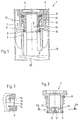
- Fig. 1 shows a sectional partial side view of the invention Plug arrangement 1.
- the housing 16, which is open at the top, is covered by a cover 17 locked.
- the cover 17 in turn consists of a lower cover 7 and a corresponding upper cover 6. This is only in FIG. 1 the area indicated above one of the cells 3.
- the lower cover 7 detects webs 18 directed above.
- the upper cover 6 corresponds to this formed and has downward webs 19 which with the webs 18 of the lower cover 7 are firmly connected. This can be done, for example Gluing can be achieved.
- the webs 18 and 19 define the cavity 5 of the Cover 17 with formation of a degassing line a labyrinth branch.
- the cover 17 has a cell opening 2.
- the cell opening 2 has a Plug 4 closed.
- the cell opening 2 is with an internal thread and the sealing plug 4 with one corresponding external thread.
- a Round seal 8 is provided, which is screwed in the plug rests sealingly on the upper cover 6.
- the round seal 8 which is preferably is designed as an O-ring, the cavity 5 is opposite to the accumulator surrounding atmosphere sealed.
- the sealing plug 4 On the foot side, the sealing plug 4 a circumferential lamellar seal 9.
- the lamella seal 9 is in the range of the lower cover 7 sealing against the wall surrounding the cell opening 2 and seals the cavity 5 from the cell interior 3.
- the lateral surface 11 of the Stopper 4 provided with an opening 10.
- This opening 10 is included screwed plug 4 directly opposite the cavity access 15, the lower edge of the opening 10 slightly below the lower edge of the Cavity access 15 is arranged.
- the cell interior 3 with the in Cover 17 formed cavity 5 in fluid communication.
- the Opening 10 thus enables degassing of the cell 3.
- the acid 20 passes through in an uncontrolled manner the opening 10 flows into the cavity 5 of the cover 17, the opening 10 closed with a sealing membrane 12.
- the sealing membrane 12 is designed as a two-way sealing membrane. For one thing the degassing of the cell 3 ensured, on the other hand, it can be in the cavity 5 separating acid mist through the opening 10 back into the Get inside the cell 3. Also in the event that acid at a correspondingly high Internal pressure is pressed out of the cell interior 3 into the cavity 5 a backflow possible.
- the plug arrangement according to the invention can therefore be used 1 ensure that acid from the battery case even then does not run out when the accumulator is out of its normal position is twisted or tilted.
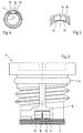
- the sealing membrane 12 is below Formation of a plurality of passage gaps 14 each consisting of two ones defined on one side flexible sub-membranes 13 formed.
- the sub-membranes 13 are in here Direction of the cavity 5 is pivotally arranged. This will in advantageously supports degassing of the cell 3, so that the Can separate acid mist in the cavity 5 of the cover 17, the gaps 14 a backflow of the acid located in the cavity 5 back into the Allow cell interior 3. Nevertheless, the sealing membrane 12 prevents Outflow of the acid 20 located inside the cell 3 into the cavity 5 due to the battery tipping over.
- FIG. 2 shows an enlarged view of section II according to FIG. 1 can be seen here the arrangement of a partial membrane 13 with the formation of Flow gaps 14.
- Fig. 3 shows a sectional side view of the invention Sealing plug 14.
- the Sealing plug 4 shown in Fig. 3 rotated by 90 °.
- the sealing membrane 12 formed from two partial membranes 13 two sub-membranes 13 are in the form of sealing arms with the formation of Passage columns 14 arranged adjacent to each other.
- the partial membrane 13 are arranged pivotably in the direction of the cavity 5. This The relationship is in particular FIG. 4 or the enlargement according to Fig. 5 can be seen.
- Fig. 6 shows the plug 4 according to the invention in a side view.
- Round seal 8 lamellar seal 9 and 13 consisting of partial membranes Sealing membrane 12 is integrally formed on the plug 4 and in Two-component process made by injection molding.
- Two-component process made by injection molding.
- One in particular economical production is hereby achieved.
- Plug 4 to adapt to different types of batteries.
Landscapes
- Chemical & Material Sciences (AREA)
- Chemical Kinetics & Catalysis (AREA)
- Electrochemistry (AREA)
- General Chemical & Material Sciences (AREA)
- Gas Exhaust Devices For Batteries (AREA)
- Separation Using Semi-Permeable Membranes (AREA)
- Connector Housings Or Holding Contact Members (AREA)
Abstract
Description
- Fig. 1
- eine geschnittene Teilseitenansicht der erfindungsgemäßen Stopfenanordnung;
- Fig. 2
- einen Teilausschnitt gemäß Fig. 1;
- Fig. 3
- eine geschnittene Seitenansicht des erfindungsgemäßen Verschlußstopfens;
- Fig. 4
- eine geschnittene Ansicht gemäß der Schnittlinie IV-IV nach Fig. 3;
- Fig. 5
- einen Teilausschnitt gemäß Fig. 4;
- Fig. 6
- eine Seitenansicht des erfindungsgemäßen Verschlußstopfens.
- 1
- Stopfenanordnung
- 2
- Zellenöffnung
- 3
- Zelle
- 4
- Verschlußstopfen
- 5
- Hohlraum
- 6
- Oberdeckel
- 7
- Unterdeckel
- 8
- Runddichtung
- 9
- Lamellendichtung
- 10
- Öffnung
- 11
- Mantelfläche
- 12
- Dichtmembran
- 13
- Teilmembran
- 14
- Spalt
- 15
- Hohlraumzugang
- 16
- Gehäuse
- 17
- Deckel
- 18
- Steg
- 19
- Steg
- 20
- Säure
Claims (12)
- Stopfenanordnung zum gasdichten Verschließen einer Zellenöffnung (2) eines Akkumulators, gebildet aus einem in die Zellenöffnung (2) abdichtend einsetzbaren Verschlußstopfen (4), wobei das Zelleninnere (3) zur Säureabscheidung über eine mit einer Zweiwegedichtmembran (12) versehene Öffnung (10) in der Mantelfläche (11) des Verschlußstopfens (4) strömungstechnisch mit einem zwischen Ober- und Unterdeckel (6, 7) des Gehäusedeckels (17) ausgebildeten Hohlraum (5) in Verbindung steht.
- Stopfenanordnung nach Anspruch 1, dadurch gekennzeichnet, daß die Dichtmembran (12) an wenigstens einer Stelle unter Bildung einer Durchlaßöffnung mit einem Durchbruch (14) versehen ist.
- Stopfenanordnung nach den Ansprüchen 1 und 2, dadurch gekennzeichnet, daß der Durchbruch ein Spalt (14) ist.
- Stopfenanordnung nach Anspruch 1, dadurch gekennzeichnet, daß die Dichtmembran (12) aus jeweils zwei einseitig festgelegten flexiblen Teilmembranen (13) gebildet ist.
- Stopfenanordnung nach Anspruch 4, dadurch gekennzeichnet, daß die Teilmembranen (13) in Richtung auf den Hohlraum (5) verschwenkbar angeordnet sind.
- Stopfenanordnung nach einem der vorhergehenden Ansprüche, dadurch gekennzeichnet, daß die in der Mantelfläche (11) des Verschlußstopfens (4) ausgebildete Öffnung (10) bei einem in die Zellenöffnung (2) eingesetzten Verschlußstopfen (4) dem Hohlraumzugang (15) gegenüberliegend angeordnet ist.
- Stopfenanordnung nach einem der vorhergehenden Ansprüche, dadurch gekennzeichnet, daß der Verschlußstopfen (4) kopfseitig eine umlaufende Dichtung (8) aufweist, die bei einem in die Zellenöffnung (2) eingesetzten Verschlußstopfen (4) im Bereich des Oberdeckels (6) dichtend an die Zellenöffnung (2) umgebenden Wandung anliegt und den Hohlraum (5) gegenüber der den Akkumulator umgebenden Atmosphäre abdichtet.
- Stopfenanordnung nach Anspruch 7, dadurch gekennzeichnet, daß die umlaufende Dichtung eine Runddichtung (8), vorzugsweise ein O-Ring ist.
- Stopfenanordnung nach einem der vorhergehenden Ansprüche, dadurch gekennzeichnet, daß der Verschlußstopfen (4) fußseitig eine umlaufende Dichtung (9) aufweist, die bei einem in die Zellenöffnung (2) eingesetzten Verschlußstopfen (4) im Bereich des Unterdeckels (7) dichtend an der die Zellenöffnung (2) umgebenden Wandung anliegt und den Hohlraum (5) gegenüber dem Zelleninneren (3) abdichtet.
- Stopfenanordnung nach Anspruch 9, dadurch gekennzeichnet, daß die umlaufende Dichtung eine Lamellendichtung (9) ist.
- Stopfenanordnung nach Anspruch 10, dadurch gekennzeichnet, daß die Lamellendichtung (9) toleranzausgleichend ausgebildet ist.
- Stopfenanordnung nach einem der vorhergehenden Ansprüche, dadurch gekennzeichnet, daß sowohl die Runddichtung (8) als auch die Lamellendichtung (9) jeweils einstückig am Verschlußstopfen (4) angeformt ist.
Applications Claiming Priority (2)
| Application Number | Priority Date | Filing Date | Title |
|---|---|---|---|
| DE10023747 | 2000-05-15 | ||
| DE10023747A DE10023747A1 (de) | 2000-05-15 | 2000-05-15 | Stopfenanordnung |
Publications (3)
| Publication Number | Publication Date |
|---|---|
| EP1156538A2 true EP1156538A2 (de) | 2001-11-21 |
| EP1156538A3 EP1156538A3 (de) | 2004-10-06 |
| EP1156538B1 EP1156538B1 (de) | 2007-06-27 |
Family
ID=7642105
Family Applications (1)
| Application Number | Title | Priority Date | Filing Date |
|---|---|---|---|
| EP01111511A Expired - Lifetime EP1156538B1 (de) | 2000-05-15 | 2001-05-11 | Stopfenanordnung |
Country Status (5)
| Country | Link |
|---|---|
| US (1) | US6677075B2 (de) |
| EP (1) | EP1156538B1 (de) |
| AT (1) | ATE365977T1 (de) |
| DE (2) | DE10023747A1 (de) |
| ES (1) | ES2286055T3 (de) |
Cited By (4)
| Publication number | Priority date | Publication date | Assignee | Title |
|---|---|---|---|---|
| WO2006119731A3 (de) * | 2005-05-10 | 2008-07-31 | Vb Autobatterie Gmbh & Co Kgaa | Akkumulator |
| WO2010000356A3 (de) * | 2008-07-03 | 2010-02-25 | Sartorius Stedim Biotech Gmbh | Adapter zur befestigung eines filterelementes |
| WO2014195466A1 (de) * | 2013-06-06 | 2014-12-11 | Johnson Controls Autobatterie Gmbh & Co. Kgaa | Verschlussstopfenanordnung, gehäuse eines akkumulators und akkumulator |
| WO2018127410A1 (de) * | 2017-01-03 | 2018-07-12 | Johnson Controls Autobatterie Gmbh & Co. Kgaa | Stopfen zum verschliessen und abdichten einer öffnung in einem gehäuse eines energiespeichersystems und energiespeichersystem |
Families Citing this family (15)
| Publication number | Priority date | Publication date | Assignee | Title |
|---|---|---|---|---|
| PT1341244E (pt) † | 2001-12-17 | 2006-08-31 | Akkumulatorenfabrik Moll Gmbh | Acumulador com uma tampa de duas partes |
| DE10257918C5 (de) * | 2001-12-17 | 2013-12-19 | Akkumulatorenfabrik Moll Gmbh & Co. Kg | Akkumulator |
| DE10255290B4 (de) | 2002-11-26 | 2006-02-16 | Vb Autobatterie Gmbh | Akkumulator und Verschlussstopfen für einen Akkumulator |
| US20060141342A1 (en) * | 2004-12-23 | 2006-06-29 | David Marconi | Heat dissipating vent cap for battery |
| US20090042065A1 (en) * | 2007-08-10 | 2009-02-12 | Mphase Technologies, Inc. | Event Activated Micro Control Devices |
| DE102008031171B4 (de) | 2008-07-03 | 2010-12-23 | Sartorius Stedim Biotech Gmbh | Ventil |
| US8715843B2 (en) * | 2010-02-17 | 2014-05-06 | Doyle Manufacturing, Inc. | Vent cap including watering valve, float and fluid flow path that does not impinge float |
| ITMI20110478A1 (it) * | 2011-03-25 | 2012-09-26 | Accuma Spa | Coperchio per batterie elettrolitiche con degasaggio centralizzato. |
| JP1599708S (de) * | 2017-05-18 | 2018-03-19 | ||
| JP1599711S (de) * | 2017-05-18 | 2018-03-19 | ||
| EP3701577A1 (de) * | 2017-10-25 | 2020-09-02 | Clarios Advanced Solutions GmbH | Anschlusspol für einen akkumulator und akkumulatorgehäuse |
| KR102164254B1 (ko) * | 2017-11-15 | 2020-10-12 | 주식회사 엘지화학 | 이차 전지 및 그의 제조 방법, 이차 전지용 파우치 및 그의 제조 방법 |
| DE102020215372A1 (de) * | 2020-12-04 | 2022-06-09 | Mahle International Gmbh | Verschlussstopfen für einen Sammler eines Kältemittelkreislaufs |
| USD1059289S1 (en) * | 2023-03-09 | 2025-01-28 | Gs Yuasa International Ltd. | Water addition plug for storage battery |
| CN116435613B (zh) * | 2023-03-31 | 2024-08-27 | 江苏超威电源有限公司 | 一种蓄电池化成降温装置 |
Family Cites Families (10)
| Publication number | Priority date | Publication date | Assignee | Title |
|---|---|---|---|---|
| US4052534A (en) * | 1973-05-03 | 1977-10-04 | General Battery Corporation | Battery vent plug |
| GB2069747A (en) * | 1980-02-12 | 1981-08-26 | Lucas Industries Ltd | Lead-acid batteries |
| DE8430246U1 (de) * | 1984-10-15 | 1985-01-24 | Accumulatorenwerke Hoppecke Carl Zoellner & Sohn GmbH & Co KG, 5790 Brilon | Bleiakkumulator |
| DE9209987U1 (de) * | 1992-07-24 | 1992-09-17 | Accumulatorenwerke Hoppecke Carl Zoellner & Sohn GmbH & Co KG, 5790 Brilon | Bleiakkumulator |
| DE9209986U1 (de) * | 1992-07-24 | 1992-09-17 | Accumulatorenwerke Hoppecke Carl Zoellner & Sohn GmbH & Co KG, 5790 Brilon | Bleiakkumulator |
| DE9407172U1 (de) * | 1994-04-29 | 1994-07-07 | Hagen Batterie Ag, 59494 Soest | Akkumulator mit Entgasungskanal |
| DE19527526A1 (de) * | 1995-07-27 | 1997-01-30 | Hagen Batterie Ag | Stopfenanordnung zum Verschließen einzelner Zellenöffnungen eines Akkumulators |
| FR2762933B1 (fr) * | 1997-05-02 | 2003-04-18 | Alsthom Cge Alkatel | Bouchon a soupape pour accumulateur electrique |
| DE19751136A1 (de) * | 1997-11-19 | 1999-05-27 | Hoppecke Zoellner Sohn Accu | Stopfensystem zum Verschließen von Zellenöffnungen eines Akkumulators und Akkumulatordeckel zur Verwendung des Stopfensystems |
| JP3664041B2 (ja) * | 2000-05-17 | 2005-06-22 | 株式会社村田製作所 | 電荷型センサ用増幅回路 |
-
2000
- 2000-05-15 DE DE10023747A patent/DE10023747A1/de not_active Withdrawn
-
2001
- 2001-05-11 DE DE50112653T patent/DE50112653D1/de not_active Expired - Fee Related
- 2001-05-11 ES ES01111511T patent/ES2286055T3/es not_active Expired - Lifetime
- 2001-05-11 EP EP01111511A patent/EP1156538B1/de not_active Expired - Lifetime
- 2001-05-11 AT AT01111511T patent/ATE365977T1/de not_active IP Right Cessation
- 2001-05-15 US US09/855,884 patent/US6677075B2/en not_active Expired - Fee Related
Cited By (8)
| Publication number | Priority date | Publication date | Assignee | Title |
|---|---|---|---|---|
| WO2006119731A3 (de) * | 2005-05-10 | 2008-07-31 | Vb Autobatterie Gmbh & Co Kgaa | Akkumulator |
| US7504175B2 (en) | 2005-05-10 | 2009-03-17 | Vb Autobatterie Gmbh & Co. Kgaa | Battery having a cover and a degassing channel system sealed with annular projections and sealing elements |
| CN101292375B (zh) * | 2005-05-10 | 2010-05-26 | Vb汽车电池有限责任公司 | 蓄电池 |
| WO2010000356A3 (de) * | 2008-07-03 | 2010-02-25 | Sartorius Stedim Biotech Gmbh | Adapter zur befestigung eines filterelementes |
| US8177972B2 (en) | 2008-07-03 | 2012-05-15 | Sartorius Stedim Biotech Gmbh | Adapter for fastening a filter element |
| WO2014195466A1 (de) * | 2013-06-06 | 2014-12-11 | Johnson Controls Autobatterie Gmbh & Co. Kgaa | Verschlussstopfenanordnung, gehäuse eines akkumulators und akkumulator |
| WO2018127410A1 (de) * | 2017-01-03 | 2018-07-12 | Johnson Controls Autobatterie Gmbh & Co. Kgaa | Stopfen zum verschliessen und abdichten einer öffnung in einem gehäuse eines energiespeichersystems und energiespeichersystem |
| US11894582B2 (en) | 2017-01-03 | 2024-02-06 | Clarios Germany Gmbh & Co. Kg | Stopper for closing and sealing an opening in a housing of an energy storage system and energy storage system |
Also Published As
| Publication number | Publication date |
|---|---|
| DE10023747A1 (de) | 2001-11-22 |
| ATE365977T1 (de) | 2007-07-15 |
| US20010041286A1 (en) | 2001-11-15 |
| ES2286055T3 (es) | 2007-12-01 |
| US6677075B2 (en) | 2004-01-13 |
| DE50112653D1 (de) | 2007-08-09 |
| EP1156538B1 (de) | 2007-06-27 |
| EP1156538A3 (de) | 2004-10-06 |
Similar Documents
| Publication | Publication Date | Title |
|---|---|---|
| EP1156538A2 (de) | Stopfenanordnung | |
| DE19540251C2 (de) | Kühlmittelfilter | |
| EP0920063B1 (de) | Stopfensystem zum Verschliessen von Zellenöffnungen eines Akkumulators und Akkumulatordeckel zur Verwendung des Stopfensystems | |
| EP0584490B1 (de) | Deckel für Bleiakkumulator mit Entgasungssystem | |
| DE4107616C2 (de) | Akkumulatoren-Batterie | |
| WO2006055993A1 (de) | Trennvorrichtung, insbesondere für körperflüssigkeiten, sowie aufnahmeeinrichtung mit einer derartigen trennvorrichtung | |
| DE60219854T2 (de) | Leckresistente Fahrzeugbatterie | |
| DE3729610C2 (de) | ||
| DE69212705T2 (de) | Vorrichtung zur Abführung von Abgasen, die innenliegend von Akkumulatorbatterien gebildet werden | |
| DE4216563A1 (de) | Akkumulator | |
| EP0680104A1 (de) | Akkumulator mit Entgasungskanal | |
| EP1231421B1 (de) | Dichtungsventilanordnung | |
| DE2037938A1 (de) | Entluftungs und Full Vorrichtung fur Akkumulatoren | |
| EP1156539B1 (de) | Mehrzelliger Akkumulator mit Entgasungssystem | |
| EP0639862B1 (de) | Mehrzellige Batterie | |
| EP0834935B1 (de) | Batterie mit einer Vorrichtung zur Abführung von Abgasen | |
| DE10257918C5 (de) | Akkumulator | |
| EP1341244B2 (de) | Akkumulator mit einem zweiteiligen Deckel | |
| DE60222838T2 (de) | Leck hemmende Autobatterie | |
| EP1036261B1 (de) | Verschlussdeckel | |
| EP4113727B1 (de) | Batterie | |
| EP1427038B1 (de) | Akkumulator und Verschlussstopfen für einen Akkumulator | |
| DE19953417A1 (de) | Mehrzelliger, dicht verschlossener Bleiakkumulator | |
| DE10254950B4 (de) | Akkumulator, insbesondere Bleiakkumulator | |
| DE19642238C1 (de) | Blei-Säure-Akkumulator mit Entgasungseinrichtung |
Legal Events
| Date | Code | Title | Description |
|---|---|---|---|
| PUAI | Public reference made under article 153(3) epc to a published international application that has entered the european phase |
Free format text: ORIGINAL CODE: 0009012 |
|
| AK | Designated contracting states |
Kind code of ref document: A2 Designated state(s): AT BE CH CY DE DK ES FI FR GB GR IE IT LI LU MC NL PT SE TR |
|
| AX | Request for extension of the european patent |
Free format text: AL;LT;LV;MK;RO;SI |
|
| PUAL | Search report despatched |
Free format text: ORIGINAL CODE: 0009013 |
|
| AK | Designated contracting states |
Kind code of ref document: A3 Designated state(s): AT BE CH CY DE DK ES FI FR GB GR IE IT LI LU MC NL PT SE TR |
|
| AX | Request for extension of the european patent |
Extension state: AL LT LV MK RO SI |
|
| 17P | Request for examination filed |
Effective date: 20041228 |
|
| AKX | Designation fees paid |
Designated state(s): AT BE CH CY DE DK ES FI FR GB GR IE IT LI LU MC NL PT SE TR |
|
| RAP1 | Party data changed (applicant data changed or rights of an application transferred) |
Owner name: VB AUTOBATTERIE GMBH & CO. KGAA. |
|
| GRAP | Despatch of communication of intention to grant a patent |
Free format text: ORIGINAL CODE: EPIDOSNIGR1 |
|
| GRAS | Grant fee paid |
Free format text: ORIGINAL CODE: EPIDOSNIGR3 |
|
| GRAA | (expected) grant |
Free format text: ORIGINAL CODE: 0009210 |
|
| AK | Designated contracting states |
Kind code of ref document: B1 Designated state(s): AT BE CH CY DE DK ES FI FR GB GR IE IT LI LU MC NL PT SE TR |
|
| REG | Reference to a national code |
Ref country code: GB Ref legal event code: FG4D Free format text: NOT ENGLISH |
|
| REG | Reference to a national code |
Ref country code: CH Ref legal event code: EP |
|
| REG | Reference to a national code |
Ref country code: IE Ref legal event code: FG4D Free format text: LANGUAGE OF EP DOCUMENT: GERMAN |
|
| REF | Corresponds to: |
Ref document number: 50112653 Country of ref document: DE Date of ref document: 20070809 Kind code of ref document: P |
|
| GBT | Gb: translation of ep patent filed (gb section 77(6)(a)/1977) |
Effective date: 20070821 |
|
| PG25 | Lapsed in a contracting state [announced via postgrant information from national office to epo] |
Ref country code: SE Free format text: LAPSE BECAUSE OF FAILURE TO SUBMIT A TRANSLATION OF THE DESCRIPTION OR TO PAY THE FEE WITHIN THE PRESCRIBED TIME-LIMIT Effective date: 20070927 |
|
| REG | Reference to a national code |
Ref country code: ES Ref legal event code: FG2A Ref document number: 2286055 Country of ref document: ES Kind code of ref document: T3 |
|
| NLV1 | Nl: lapsed or annulled due to failure to fulfill the requirements of art. 29p and 29m of the patents act | ||
| ET | Fr: translation filed | ||
| REG | Reference to a national code |
Ref country code: IE Ref legal event code: FD4D |
|
| PG25 | Lapsed in a contracting state [announced via postgrant information from national office to epo] |
Ref country code: PT Free format text: LAPSE BECAUSE OF FAILURE TO SUBMIT A TRANSLATION OF THE DESCRIPTION OR TO PAY THE FEE WITHIN THE PRESCRIBED TIME-LIMIT Effective date: 20071127 Ref country code: NL Free format text: LAPSE BECAUSE OF FAILURE TO SUBMIT A TRANSLATION OF THE DESCRIPTION OR TO PAY THE FEE WITHIN THE PRESCRIBED TIME-LIMIT Effective date: 20070627 Ref country code: IE Free format text: LAPSE BECAUSE OF FAILURE TO SUBMIT A TRANSLATION OF THE DESCRIPTION OR TO PAY THE FEE WITHIN THE PRESCRIBED TIME-LIMIT Effective date: 20070627 |
|
| PG25 | Lapsed in a contracting state [announced via postgrant information from national office to epo] |
Ref country code: DK Free format text: LAPSE BECAUSE OF FAILURE TO SUBMIT A TRANSLATION OF THE DESCRIPTION OR TO PAY THE FEE WITHIN THE PRESCRIBED TIME-LIMIT Effective date: 20070627 Ref country code: GR Free format text: LAPSE BECAUSE OF FAILURE TO SUBMIT A TRANSLATION OF THE DESCRIPTION OR TO PAY THE FEE WITHIN THE PRESCRIBED TIME-LIMIT Effective date: 20070928 |
|
| PLBE | No opposition filed within time limit |
Free format text: ORIGINAL CODE: 0009261 |
|
| STAA | Information on the status of an ep patent application or granted ep patent |
Free format text: STATUS: NO OPPOSITION FILED WITHIN TIME LIMIT |
|
| 26N | No opposition filed |
Effective date: 20080328 |
|
| BERE | Be: lapsed |
Owner name: VB AUTOBATTERIE G.M.B.H. & CO. KGAA Effective date: 20080531 |
|
| PG25 | Lapsed in a contracting state [announced via postgrant information from national office to epo] |
Ref country code: MC Free format text: LAPSE BECAUSE OF NON-PAYMENT OF DUE FEES Effective date: 20080531 |
|
| REG | Reference to a national code |
Ref country code: CH Ref legal event code: PL |
|
| GBPC | Gb: european patent ceased through non-payment of renewal fee |
Effective date: 20080511 |
|
| PG25 | Lapsed in a contracting state [announced via postgrant information from national office to epo] |
Ref country code: LI Free format text: LAPSE BECAUSE OF NON-PAYMENT OF DUE FEES Effective date: 20080531 Ref country code: CH Free format text: LAPSE BECAUSE OF NON-PAYMENT OF DUE FEES Effective date: 20080531 |
|
| PG25 | Lapsed in a contracting state [announced via postgrant information from national office to epo] |
Ref country code: FI Free format text: LAPSE BECAUSE OF FAILURE TO SUBMIT A TRANSLATION OF THE DESCRIPTION OR TO PAY THE FEE WITHIN THE PRESCRIBED TIME-LIMIT Effective date: 20070627 |
|
| PG25 | Lapsed in a contracting state [announced via postgrant information from national office to epo] |
Ref country code: BE Free format text: LAPSE BECAUSE OF NON-PAYMENT OF DUE FEES Effective date: 20080531 |
|
| PG25 | Lapsed in a contracting state [announced via postgrant information from national office to epo] |
Ref country code: GB Free format text: LAPSE BECAUSE OF NON-PAYMENT OF DUE FEES Effective date: 20080511 |
|
| PG25 | Lapsed in a contracting state [announced via postgrant information from national office to epo] |
Ref country code: CY Free format text: LAPSE BECAUSE OF FAILURE TO SUBMIT A TRANSLATION OF THE DESCRIPTION OR TO PAY THE FEE WITHIN THE PRESCRIBED TIME-LIMIT Effective date: 20070627 |
|
| PGFP | Annual fee paid to national office [announced via postgrant information from national office to epo] |
Ref country code: ES Payment date: 20090522 Year of fee payment: 9 |
|
| PGFP | Annual fee paid to national office [announced via postgrant information from national office to epo] |
Ref country code: AT Payment date: 20090522 Year of fee payment: 9 Ref country code: DE Payment date: 20090609 Year of fee payment: 9 Ref country code: FR Payment date: 20090519 Year of fee payment: 9 Ref country code: IT Payment date: 20090527 Year of fee payment: 9 Ref country code: LU Payment date: 20090526 Year of fee payment: 9 |
|
| PG25 | Lapsed in a contracting state [announced via postgrant information from national office to epo] |
Ref country code: TR Free format text: LAPSE BECAUSE OF FAILURE TO SUBMIT A TRANSLATION OF THE DESCRIPTION OR TO PAY THE FEE WITHIN THE PRESCRIBED TIME-LIMIT Effective date: 20070627 |
|
| PG25 | Lapsed in a contracting state [announced via postgrant information from national office to epo] |
Ref country code: AT Free format text: LAPSE BECAUSE OF NON-PAYMENT OF DUE FEES Effective date: 20100511 |
|
| REG | Reference to a national code |
Ref country code: FR Ref legal event code: ST Effective date: 20110131 |
|
| PG25 | Lapsed in a contracting state [announced via postgrant information from national office to epo] |
Ref country code: IT Free format text: LAPSE BECAUSE OF NON-PAYMENT OF DUE FEES Effective date: 20100511 |
|
| PG25 | Lapsed in a contracting state [announced via postgrant information from national office to epo] |
Ref country code: DE Free format text: LAPSE BECAUSE OF NON-PAYMENT OF DUE FEES Effective date: 20101201 |
|
| PG25 | Lapsed in a contracting state [announced via postgrant information from national office to epo] |
Ref country code: FR Free format text: LAPSE BECAUSE OF NON-PAYMENT OF DUE FEES Effective date: 20100531 |
|
| REG | Reference to a national code |
Ref country code: ES Ref legal event code: FD2A Effective date: 20110714 |
|
| PG25 | Lapsed in a contracting state [announced via postgrant information from national office to epo] |
Ref country code: ES Free format text: LAPSE BECAUSE OF NON-PAYMENT OF DUE FEES Effective date: 20110704 |
|
| PG25 | Lapsed in a contracting state [announced via postgrant information from national office to epo] |
Ref country code: ES Free format text: LAPSE BECAUSE OF NON-PAYMENT OF DUE FEES Effective date: 20100512 |
|
| PG25 | Lapsed in a contracting state [announced via postgrant information from national office to epo] |
Ref country code: LU Free format text: LAPSE BECAUSE OF NON-PAYMENT OF DUE FEES Effective date: 20100511 |