EP1156508A2 - A glass bulb for a cathode-ray tube and a cathode-ray tube device - Google Patents
A glass bulb for a cathode-ray tube and a cathode-ray tube device Download PDFInfo
- Publication number
- EP1156508A2 EP1156508A2 EP01304324A EP01304324A EP1156508A2 EP 1156508 A2 EP1156508 A2 EP 1156508A2 EP 01304324 A EP01304324 A EP 01304324A EP 01304324 A EP01304324 A EP 01304324A EP 1156508 A2 EP1156508 A2 EP 1156508A2
- Authority
- EP
- European Patent Office
- Prior art keywords
- glass
- unit
- funnel
- members
- panel
- Prior art date
- Legal status (The legal status is an assumption and is not a legal conclusion. Google has not performed a legal analysis and makes no representation as to the accuracy of the status listed.)
- Withdrawn
Links
Images



Classifications
-
- C—CHEMISTRY; METALLURGY
- C03—GLASS; MINERAL OR SLAG WOOL
- C03B—MANUFACTURE, SHAPING, OR SUPPLEMENTARY PROCESSES
- C03B27/00—Tempering or quenching glass products
- C03B27/04—Tempering or quenching glass products using gas
- C03B27/06—Tempering or quenching glass products using gas for glass products other than flat or bent glass plates, e.g. hollow glassware, lenses
-
- C—CHEMISTRY; METALLURGY
- C03—GLASS; MINERAL OR SLAG WOOL
- C03B—MANUFACTURE, SHAPING, OR SUPPLEMENTARY PROCESSES
- C03B25/00—Annealing glass products
- C03B25/04—Annealing glass products in a continuous way
- C03B25/06—Annealing glass products in a continuous way with horizontal displacement of the glass products
-
- C—CHEMISTRY; METALLURGY
- C03—GLASS; MINERAL OR SLAG WOOL
- C03C—CHEMICAL COMPOSITION OF GLASSES, GLAZES OR VITREOUS ENAMELS; SURFACE TREATMENT OF GLASS; SURFACE TREATMENT OF FIBRES OR FILAMENTS MADE FROM GLASS, MINERALS OR SLAGS; JOINING GLASS TO GLASS OR OTHER MATERIALS
- C03C27/00—Joining pieces of glass to pieces of other inorganic material; Joining glass to glass other than by fusing
- C03C27/06—Joining glass to glass by processes other than fusing
-
- H—ELECTRICITY
- H01—ELECTRIC ELEMENTS
- H01J—ELECTRIC DISCHARGE TUBES OR DISCHARGE LAMPS
- H01J29/00—Details of cathode-ray tubes or of electron-beam tubes of the types covered by group H01J31/00
- H01J29/86—Vessels; Containers; Vacuum locks
- H01J29/863—Vessels or containers characterised by the material thereof
-
- H—ELECTRICITY
- H01—ELECTRIC ELEMENTS
- H01J—ELECTRIC DISCHARGE TUBES OR DISCHARGE LAMPS
- H01J2229/00—Details of cathode ray tubes or electron beam tubes
- H01J2229/86—Vessels and containers
- H01J2229/8603—Neck or cone portions of the CRT vessel
-
- Y—GENERAL TAGGING OF NEW TECHNOLOGICAL DEVELOPMENTS; GENERAL TAGGING OF CROSS-SECTIONAL TECHNOLOGIES SPANNING OVER SEVERAL SECTIONS OF THE IPC; TECHNICAL SUBJECTS COVERED BY FORMER USPC CROSS-REFERENCE ART COLLECTIONS [XRACs] AND DIGESTS
- Y02—TECHNOLOGIES OR APPLICATIONS FOR MITIGATION OR ADAPTATION AGAINST CLIMATE CHANGE
- Y02P—CLIMATE CHANGE MITIGATION TECHNOLOGIES IN THE PRODUCTION OR PROCESSING OF GOODS
- Y02P40/00—Technologies relating to the processing of minerals
- Y02P40/50—Glass production, e.g. reusing waste heat during processing or shaping
- Y02P40/57—Improving the yield, e-g- reduction of reject rates
Definitions
- the present invention relates to a glass bulb for a cathode-ray tube (hereafter called "CRT”), and a CRT device equipped with a CRT glass bulb.
- CRT cathode-ray tube
- a CRT device is roughly made up of a CRT glass bulb and a number of members attached to outside of the glass bulb.
- the CRT glass bulb is made by integrating a plurality of glass members which include a phosphor screen, an internal electrode film, or the like and sealing with an electron gun that emits an electron beam in high vacuum.
- the number of members includes a deflection yoke to deflect the electron beam.
- FIG. 1 is a schematic sectional view to show an example construction of the conventional CRT glass bulb.
- the conventional CRT glass bulb is made by integrating a glass member 901 that forms a panel unit, a glass member 902 that forms a funnel unit, and a glass member 903 that forms a neck unit, and sealing with a glass frit or heat fusing.
- an internal electrode film 906 is formed and connected to an anode button 907 in a conductive state.
- the anode button 907 are extended to the outside of the glass bulb through the funnel unit glass member 902.
- a CRT device When compared with other types of display devices that have developed in recent years such as a liquid crystal display panel and a plasma display panel, a CRT device has a large depth, which is a major drawback. Therefore, reducing the depth is one of the important issues in developing CRT devices. However, to reduce the depth of the CRT device equipped with the glass bulb described above, mainly a depth L2 of the funnel unit has to be reduced.
- the conventional funnel unit glass member 902 is formed in one piece using pressing. Accordingly, reducing the depth of the funnel unit glass member 902 deteriorates vacuum strength and implosion-proof of the glass bulb. Therefore, the reduction of the depth of the funnel unit has already reached its limits due to the design constraints on the strength.
- An object of the present invention is to provide a glass bulb for a CRT whose funnel unit have a less depth than a conventional one and a CRT device equipped with the CRT glass bulb.
- the inventors designed a prototype of a funnel unit glass member 902 to reduce the depth of the funnel unit and at the same time to improve vacuum strength and implosion-proof.
- the prototype was broken in the pressing process and ended in failure.
- the inventors examined the cause of the failure and made the following assumption.
- the funnel unit glass member 902 and a panel unit glass member 901 are joined at a sealed portion.
- the sealed portion indicates a portion where two glass members are joined by sealing. Therefore, the thickness of the portion of the funnel unit glass member 902 which is to be joined to the panel unit glass member 901 needs to be substantially the same as the thickness of the portion of the panel unit glass member 901 which is to be joined to the funnel unit glass member 902.
- the sealed portion between the panel unit glass member 901 and the funnel unit glass member 902 is preferably as thick as 15mm to 30mm.
- thickness of the portion of the funnel unit glass member 902 which is to be joined to the neck unit glass member 903 also needs to be substantially the same as the thickness of the portion of the neck unit glass member 903 which is to be joined to the funnel unit glass member 902.
- members such as a deflection yoke for deflecting an electron beam have to be provided around the sealed portion. Hence, it is necessary to make the sealed portion thin in order to increase the magnetic flux density of the deflection yoke.
- the conventional funnel unit glass member 902 needs to be approximately 15-30mm thick at the portion which is to be joined to the panel unit glass member 901 and approximately 2-3mm thick at the portion which is to be joined to the neck unit glass member 903.
- a maximum-to-minimum thickness ratio of the funnel unit glass member 902 is approximately 10:1.
- the inventors assumed that the prototype of the funnel unit glass member was broken because such a large maximum-to-minimum thickness ratio of the funnel unit glass member 902 caused the difference in cooling rates during the pressing process between the thickest portion and the thinnest portion of the funnel unit glass member 902. In other words, if the maximum-to-minimum thickness ratio had been set within a certain range, it would have been possible to make the sealed portion between the funnel unit glass member 902 and the panel unit glass member 901 sufficiently thick.
- a glass bulb for a cathode-ray tube including: a panel unit having a panel screen; a neck unit holding an electron gun; and a funnel unit having a funnel-like shape, wherein the panel unit and the neck unit are bridged by the funnel unit, wherein the funnel unit is formed from a plurality of glass members, the plurality of glass members including at least a first glass member on a side of the panel unit and a second glass member on a side of the neck unit, and wherein a maximum-to-minimum thickness ratio of each of the plurality of glass members is designed to be within a range suitable for producing the plurality of glass members using pressing, the maximum-to-minimum thickness ratio being a ratio of thickness of a thickest portion to thickness of a thinnest portion.
- the portion of the funnel unit glass member 902 which is to be joined to a panel unit glass member 901 can be made thicker enough to improve the vacuum strength and the implosion-proof while reducing the depth of the funnel unit.
- the range of the maximum-to-minimum thickness ratio suitable for producing the glass members using pressing is likely to vary depending on which type of glass material is used. For example, when a glass material conforming to EIAJ(Electronic Industries Association of Japan) LOF-03 is used, the inventors found that the maximum thickness needs to be no more than about five times the minimum thickness.
- the inventors examined to use strengthened glass for the funnel unit in order to further improve the vacuum strength and the implosion-proof.
- the physical strengthening can be performed by air-cooling the glass member molded by pressing, heating it again to a temperature which is 20-40°C lower than an annealing point, and cooling it slowly.
- the inventors confirmed that if the maximum-to-minimum thickness ratio is in the suitable range for producing the glass member using pressing, it is possible to physically strengthen the glass member.
- strengthened glass can be used in at least part of the funnel unit. As a result, even if the depth of the funnel unit is reduced, the vacuum strength and the implosion-proof can be improved.
- the plurality of glass members that form the funnel unit is preferably joined by sealing with a glass frit so that the inside of the glass bulb is kept in a vacuum state. This is because, under the present circumstances, it is not preferable to use a method such as fusion sealing to seal strengthened glass.
- the funnel unit is formed from two glass members: a glass member to be joined to the panel unit grass member and a glass member to be joined to a neck unit glass member.
- the former funnel unit glass member and the latter funnel unit glass member are preferably joined at a position including an inflection point on a periphery of the funnel unit on a supposed plane substantially perpendicular to the tube axial direction.
- the thickness of the glass bulb changes most sharply around the position. If the funnel unit is cut at the position, it can be efficiently divided into a thick glass member and a thin glass member.
- the glass members with such shapes are easy to produce. Furthermore, each area of the sealedportion is sufficiently large. Therefore, this construction is preferable in consideration of the strength of the integrated glass bulb.
- the shape of the original member indicates the shape of the panel unit glass member when a shape of the funnel unit glass member is substantially the same as a shape in which a certain portion is removed from the panel unit glass member.
- the glass member which is to be joined to the panel unit glass member is preferable to be formed in one piece and physically strengthened.
- strengthened glass is used around a sealed portion between the panel unit and the funnel unit.
- the sealed portion can be thinner, and the glass bulb can be lightened.
- the glass bulb has a lead terminal connected to each internal electrode film which is provided on an inner surface of the funnel unit.
- the lead terminal is preferably extended to the outside of the glass bulb through a sealed portion between two out of the plurality of funnel unit glass members.
- the lead terminal is provided so as to pass through the funnel unit glass member by heating part of it.
- the conventional method cannot be used because it is not preferable to heat strengthened glass to pass the lead terminal through the funnel unit glass members under the present circumstances.
- a glass bulb for a CRT including: a panel unit having a panel screen; a neck unit holding an electron gun; and a funnel unit having a funnel-like shape, wherein the panel unit and the neck unit are bridged by the funnel unit, and wherein physically strengthened glass is used in at least part of the funnel unit.
- the object is further achieved by a manufacturing method of a glass bulb for a CRT including: a panel unit having a panel screen; a neck unit holding an electron gun; and a funnel unit having a funnel-like shape, wherein the panel unit and the neck unit are bridged by the funnel unit, the manufacturing method including: a glass member preparing step for preparing at least one physically strengthened glass member for the funnel unit, the funnel unit being formed from a plurality of glass members; and a glass bulb forming step for forming the glass bulb from the plurality of glass members including the glass member which is prepared in the glass member preparing step.
- the glass members may be prepared by buying as well as by producing.
- the object is achieved by a CRT device equipped with the glass bulb of the present invention or the glass bulb produced according to the manufacturing method of the present invention.
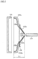
- FIG.2 is a schematic sectional view showing an example construction of the CRT glass bulb of the present embodiment.
- the glass bulb is made by integrating a panel unit glass member 101, two funnel unit glass members 102a and 102b, and the neck unit glass member 103.
- the funnel unit glass member 102a is to be joined to the panel unit glass member 101
- the funnel unit glass member 102b is to be joined to a glass member 103 for a neck unit.
- a lead terminal 108 which is connected to internal electrode films 106a and 106b in a conductive state is provided between the two funnel unit glass members 102a and 102b and extended to the outside of the glass bulb.
- the internal electrode films 106a and 106b are formed through a general procedure using brushing or pouring a material made mainly from carbon and liquid glass, and they may be formed either of before or after the funnel unit glass members 102a and 102b are joined.
- a general material which is used for a vacuum tube can be used for the lead terminal 108.
- the general material is conductive and has a highermelting point than a softening point of glass which is used for the funnel unit glass members 102a and 102b.
- a softening point of glass which is used for the funnel unit glass members 102a and 102b.
- an alloy of nickel, chromium, and iron whose coefficient of thermal expansion is similar to that of glass can be used.
- the lead terminal 108 is preferably as small and thin as possible because the inside of the glass bulb has to be kept in a vacuum state.
- the panel unit glass member 101 and the funnel unit glass member 102a, and the funnel unit glass member 102b and the neck unit glass member 103 are joined by respective predetermined methods. Then, an electron gun and the like (unshown in the figure) are provided on the inner surface of the joined glass members. And finally, it is sealed in high vacuum.
- the glass bulb produced in this way is provided as a member of a CRT device.
- the shapes of the funnel unit glass members 102a and 102b are adjusted so that an sectional area of a sealed portion is sufficiently large to be sealed using a glass frit such as a frit glass 1307R made by ASAHI GLASS Company Ltd.
- the sealed portion indicates a portion where two glass members are joined by sealing.
- an end of the funnel unit glass member 102b which is to be joined to the funnel unit glass member 102a, may be bent to outside of the glass bulb so that a surface of the bent portion can be joined to an end of the funnel unit glass member 102a.
- both joined portions of the funnel unit glass members 102a and 102b may be shaped a cuneiform. Both methods provide sufficiently large areas.
- the preferable areas of the joined portions are likely to vary depending on other conditions, so that they need to be decided in each case in consideration of the conditions.
- the funnel unit glass members 102a and 102b are designed so that each maximum-to-minimum thickness ratio is in a suitable range for producing the glass members using pressing.
- the sealed portion between the funnel unit glass members 102a and the panel unit glass member 101 can be sufficiently thick, so that the depth of the funnel unit can be reduced.
- the range of the maximum-to-minimum thickness ratio is likely to vary depending on a type of glass material or the like.
- the inventors confirmed that when the maximum thickness is designed to be no more than substantially five times the minimum thickness, the glass members can be produced using pressing and also physically strengthened.
- FIG. 3 shows the relationship between process timings and glass temperatures when producing a glass member to be physically strengthened in the present embodiment.
- glass which is heated to approximately 1000°C and melted is molded an end shape by pouring into a mold and pressing (A in the figure) . Then, the glass member is air-cooled, that prevents deformation and significantly strengthens the glass member. Next, the glass member is heated again to 450-470°C in an electric furnace or the like (B in the figure), which is 20-40°C lower than an annealing point (approximately 490°C). The highest temperature in heating determines physical strength of the glass member because the physical strength depends on a gradient of a temperature curve at the distortion point in the slow cooling process.
- the problem is prevented by designing the funnel unit glass member on a condition that the maximum-to-minimum thickness ratio is in a suitable range for producing the glass member using pressing.
- the funnel unit glass member is physically strengthened approximately by 40 percent. Therefore, vacuum strength and implosion-proof can be improved even if the depth of the funnel unit is reduced.
- the depth was reduced approximately 20-30mm.
- the thickest portion of the funnel unit glass member 102a was on the side of the panel unit glass member 901 and measured 24.5mm thick; and the thinnest portion was on the side of the funnel unit glass member 102b and measured 12.5mm thick. Then the maximum-to-minimum thickness ratio of the funnel unit glass member 102a was 1.96. And the thickest portion of the funnel unit glass member 102b was on the side of the funnel unit glass member 102a and measured 11.0mm; and the thinnest portion was on the side of the neck unit glass member 103 and measured 2.54mm thick. Then the maximum-to-minimum thickness ratio of the funnel unit glass member 102b was approximately 4.3.
- the glass bulb explained above is added by the deflection yoke, a convergence yoke, adjusting coils, and a variety of circuits to produce a CRT device that can display images.
- the description of the manufacturing method of the CRT device is omitted because a conventional manufacturing method can be used.
Landscapes
- Chemical & Material Sciences (AREA)
- Engineering & Computer Science (AREA)
- Materials Engineering (AREA)
- Organic Chemistry (AREA)
- Ceramic Engineering (AREA)
- Thermal Sciences (AREA)
- Physics & Mathematics (AREA)
- Life Sciences & Earth Sciences (AREA)
- Chemical Kinetics & Catalysis (AREA)
- General Chemical & Material Sciences (AREA)
- Geochemistry & Mineralogy (AREA)
- Vessels, Lead-In Wires, Accessory Apparatuses For Cathode-Ray Tubes (AREA)
- Manufacture Of Electron Tubes, Discharge Lamp Vessels, Lead-In Wires, And The Like (AREA)
Abstract
Description
Claims (18)
- A glass bulb for a cathode-ray tube comprising: a panel unit having a panel screen; a neck unit holding an electron gun; and a funnel unit having a funnel-like shape, wherein the panel unit and the neck unit are bridged by the funnel unit, whereinthe funnel unit is formed from a plurality of glass members, the plurality of glass members including at least a first glass member on a side of the panel unit and a second glass member on a side of the neck unit, anda maximum-to-minimum thickness ratio of each of the plurality of glass members is designed to be within a range suitable for producing the plurality of glass members using pressing, the maximum-to-minimum thickness ratio being a ratio of thickness of a thickest portion to thickness of a thinnest portion.
- The glass bulb of claim 1,wherein the plurality of glass members are prepared by using a glass material conforming to EIAJ(Electronic Industries Association of Japan)·LOF-03, andin each of the plurality of glass members, the maximum thickness is no more than substantially five times the minimum thickness.
- The glass bulb of claim 1,
wherein at least one of the plurality of glass members is designed to be physically strengthened. - The glass bulb of claim 3,
wherein the physical strengthening is performed by air-cooling a glass member molded by pressing, heating the glass member again to a temperature which is 20-40°C lower than an annealing point, and cooling the glass member slowly. - The glass bulb of claim 1,
wherein the plurality of glass members are joined by sealing with a glass frit so that inside of the glass bulb is kept in a vacuum state. - The glass bulb of claim 1,wherein the funnel unit is formed from two glass members, which are (a) the first glass member to be joined to the panel unit and (b) the second glass member to be joined to the neck unit, the panel unit and the neck unit being made of a glass material, andwherein the first glass member and the second glass member are joined at a position including an inflection point on a periphery of the funnel unit on a supposed plane substantially perpendicular to a tube axial direction.
- The glass bulb of claim 6,
wherein the first glass member has substantially a same shape as a shape in which a certain portion is removed from the panel unit. - The glass bulb of claim 1,
wherein the first glass member which is to be joined to the panel unit is formed in one piece and designed to be physically strengthened, the panel unit being made of a glass material. - The glass bulb of claim 1,
wherein a lead terminal is (a) connected to an electrode formed on an inner surface of the funnel unit and (b) extended to outside of the glass bulb through a sealed portion, the sealed portion being where at least two out of the plurality of glass members are joined. - The glass bulb of claim 1,
wherein a panel unit glass member that forms the panel unit is designed to be physically strengthened. - A glass bulb for a cathode-ray tube comprising: a panel unit having a panel screen; a neck unit holding an electron gun; and a funnel unit having a funnel-like shape, wherein the panel unit and the neck unit are bridged by the funnel unit, wherein
physically strengthened glass is used in at least part of the funnel unit. - A manufacturing method of a glass bulb for a cathode-ray tube including: a panel unit having a panel screen; a neck unit holding an electron gun; and a funnel unit having a funnel-like shape, wherein the panel unit and the neck unit are bridged by the funnel unit, the manufacturing method comprising:a glass member preparing step for preparing at least one physically strengthened glass member for the funnel unit, the funnel unit being formed from a plurality of glass members; anda glass bulb forming step for forming the glass bulb from the plurality of glass members including the glass member which is prepared in the glass member preparing step .
- A cathode-ray tube device comprising:a glass bulb for the cathode-ray tube including: a panel unit having a panel screen; a neck unit holding an electron gun; and a funnel unit having a funnel-like shape, wherein the panel unit and the neck unit are bridged by the funnel unit, whereinthe funnel unit is formed from a plurality of glass members, the plurality of glass members including at least a first glass member on a side of the panel unit and a second glass member on a side of the neck unit, anda maximum-to-minimum thickness ratio of each of the plurality of glass members is designed to be within a range suitable for producing the plurality of glass members using pressing, the maximum-to-minimum thickness ratio being a ratio of thickness of a thickest portion to thickness of a thinnest portion.
- The cathode-ray tube device of Claim.13,wherein the plurality of glass members are prepared by using a glass material conforming to EIAJ(Electronic Industries Association of Japan) · LOF-03, andin each of the plurality of glass members, the maximum thickness is no more than substantially five times the minimum thickness.
- The cathode-ray tube device of Claim.13,
wherein at least one of the plurality of glass members is designed to be physically strengthened. - The cathode-ray tube device of Claim.13,
wherein the plurality of glass members are joined by sealing with a glass frit so that inside of the glass bulb is kept in a vacuum state. - The cathode-ray tube device of Claim.13,
wherein a lead terminal is (a) connected to an electrode formed on an inner surface of the funnel unit and (b) extended to outside of the glass bulb through a sealed portion, the sealed portion being where at least two out of the plurality of glass members are joined. - A cathode-ray tube device comprising:a glass bulb for the cathode-ray tube including: a panel unit having a panel screen; a neck unit holding an electron gun; and a funnel unit having a funnel-like shape, wherein the panel unit and the neck unit are bridged by the funnel unit, whereinphysically strengthened glass is used in at least part of the funnel unit.
Applications Claiming Priority (2)
| Application Number | Priority Date | Filing Date | Title |
|---|---|---|---|
| JP2000142455 | 2000-05-15 | ||
| JP2000142455A JP2001325898A (en) | 2000-05-15 | 2000-05-15 | Glass bulb for cathode ray tube and cathode ray tube device |
Publications (2)
| Publication Number | Publication Date |
|---|---|
| EP1156508A2 true EP1156508A2 (en) | 2001-11-21 |
| EP1156508A3 EP1156508A3 (en) | 2006-05-03 |
Family
ID=18649423
Family Applications (1)
| Application Number | Title | Priority Date | Filing Date |
|---|---|---|---|
| EP01304324A Withdrawn EP1156508A3 (en) | 2000-05-15 | 2001-05-15 | A glass bulb for a cathode-ray tube and a cathode-ray tube device |
Country Status (6)
| Country | Link |
|---|---|
| US (1) | US6727640B2 (en) |
| EP (1) | EP1156508A3 (en) |
| JP (1) | JP2001325898A (en) |
| KR (1) | KR20010106251A (en) |
| CN (1) | CN1203517C (en) |
| TW (1) | TW533448B (en) |
Cited By (2)
| Publication number | Priority date | Publication date | Assignee | Title |
|---|---|---|---|---|
| WO2003060943A1 (en) * | 2002-01-18 | 2003-07-24 | Koninklijke Philips Electronics N.V. | Method for manufacturing a glass funnel for a cathode ray tube |
| DE10312984B3 (en) * | 2003-03-24 | 2004-05-27 | Schott Glas | Production of thermally pre-stressed glass screens for cathode ray tubes comprises pressing raw screens made from molten glass gob and thermally treating in a relaxation process in a cooling strip path |
Families Citing this family (1)
| Publication number | Priority date | Publication date | Assignee | Title |
|---|---|---|---|---|
| KR20030060235A (en) * | 2002-01-07 | 2003-07-16 | 삼성에스디아이 주식회사 | Cathode ray tube with multi-neck |
Family Cites Families (20)
| Publication number | Priority date | Publication date | Assignee | Title |
|---|---|---|---|---|
| BE421879A (en) * | 1936-07-18 | |||
| US2866187A (en) * | 1955-01-13 | 1958-12-23 | Richard A Fisch | Insulating shield and mounting device for color television tubes |
| US3445316A (en) * | 1966-04-14 | 1969-05-20 | Corning Glass Works | Method of differential chemical tempering glass and article |
| JPS5474063A (en) | 1977-11-24 | 1979-06-13 | Canon Kk | Elastic roller |
| JPS5657463A (en) | 1979-10-18 | 1981-05-19 | Daiichi Shokai Kk | Pinball machine |
| JPS59189541A (en) * | 1983-04-11 | 1984-10-27 | Toshiba Corp | Cathode ray tube |
| US4566893A (en) * | 1984-10-03 | 1986-01-28 | Rca Corporation | Method for fabricating a glass CRT panel |
| US4656388A (en) * | 1985-05-17 | 1987-04-07 | Zenith Electronics Corporation | Tensed mask color cathode ray tube and mask support frame therefore |
| FR2629267B1 (en) * | 1988-03-22 | 1996-01-26 | Thomson Csf | DEVICE FOR CHROMATICALLY CONVERTING AN IMAGE OBTAINED IN ELECTROMAGNETIC RADIATION AND MANUFACTURING METHOD THEREOF |
| DE68904843T2 (en) * | 1988-08-30 | 1993-05-27 | Toshiba Kawasaki Kk | COLOR CATHODE JET PIPES AND TUBE PISTON FOR COLOR CATHODE JET PIPES. |
| JP3090703B2 (en) | 1991-03-25 | 2000-09-25 | 株式会社東芝 | Picture tube manufacturing method |
| JP2671766B2 (en) * | 1993-06-30 | 1997-10-29 | 旭硝子株式会社 | Glass bulb for cathode ray tube |
| JP3215765B2 (en) | 1993-12-28 | 2001-10-09 | 三菱電機株式会社 | Picture tube manufacturing method |
| JP2904067B2 (en) | 1994-09-14 | 1999-06-14 | 旭硝子株式会社 | Glass bulb for cathode ray tube |
| JPH10154472A (en) * | 1996-09-30 | 1998-06-09 | Toshiba Corp | Cathode ray tube device |
| JPH10144238A (en) * | 1996-11-12 | 1998-05-29 | Toshiba Corp | Cathode ray tube and method of manufacturing the same |
| JP3379630B2 (en) * | 1997-09-08 | 2003-02-24 | 日本電気硝子株式会社 | Glass funnel for cathode ray tube |
| JPH11186754A (en) | 1997-12-25 | 1999-07-09 | Yazaki Corp | Circuit formation method in molded body |
| KR100307158B1 (en) * | 1998-09-19 | 2001-11-15 | 김순택 | Cathode ray tube |
| KR100286587B1 (en) * | 1998-10-01 | 2001-04-16 | 김순택 | Cathode ray tube |
-
2000
- 2000-05-15 JP JP2000142455A patent/JP2001325898A/en active Pending
-
2001
- 2001-05-07 US US09/850,333 patent/US6727640B2/en not_active Expired - Fee Related
- 2001-05-14 TW TW090111499A patent/TW533448B/en not_active IP Right Cessation
- 2001-05-15 CN CNB01121497XA patent/CN1203517C/en not_active Expired - Fee Related
- 2001-05-15 EP EP01304324A patent/EP1156508A3/en not_active Withdrawn
- 2001-05-15 KR KR1020010026490A patent/KR20010106251A/en not_active Ceased
Cited By (2)
| Publication number | Priority date | Publication date | Assignee | Title |
|---|---|---|---|---|
| WO2003060943A1 (en) * | 2002-01-18 | 2003-07-24 | Koninklijke Philips Electronics N.V. | Method for manufacturing a glass funnel for a cathode ray tube |
| DE10312984B3 (en) * | 2003-03-24 | 2004-05-27 | Schott Glas | Production of thermally pre-stressed glass screens for cathode ray tubes comprises pressing raw screens made from molten glass gob and thermally treating in a relaxation process in a cooling strip path |
Also Published As
| Publication number | Publication date |
|---|---|
| US6727640B2 (en) | 2004-04-27 |
| US20010043041A1 (en) | 2001-11-22 |
| CN1203517C (en) | 2005-05-25 |
| JP2001325898A (en) | 2001-11-22 |
| CN1324102A (en) | 2001-11-28 |
| EP1156508A3 (en) | 2006-05-03 |
| KR20010106251A (en) | 2001-11-29 |
| TW533448B (en) | 2003-05-21 |
Similar Documents
| Publication | Publication Date | Title |
|---|---|---|
| US5925977A (en) | Strengthened glass bulb for a cathode ray tube | |
| US6727640B2 (en) | Glass bulb for a cathode-ray tube and a cathode-ray tube device | |
| KR880003374Y1 (en) | Flat cathode ray tube | |
| US7154215B2 (en) | Color cathode ray tube capable of reducing stress | |
| KR100554420B1 (en) | Colored cathode ray tube | |
| US6861795B2 (en) | Funnel for cathode ray tube | |
| KR100494748B1 (en) | Glass Structure of CRT | |
| Smith et al. | Design and Development of the 21CYP22 21-Inch Glass Color Picture Tube | |
| US7291964B2 (en) | Color cathode ray tube | |
| KR20030068260A (en) | A Flat Type Color Cathode Ray Tube | |
| US6362564B1 (en) | Color cathode ray tube with prescribed neck thickness | |
| US20050052112A1 (en) | Color cathode ray tube | |
| EP1564781B1 (en) | Cathode-ray tube apparatus | |
| KR100256980B1 (en) | Flat type cathode ray tube | |
| KR100329568B1 (en) | Funnel of cathode ray tube | |
| KR100329567B1 (en) | Funnel of cathode ray tube | |
| KR100403769B1 (en) | the color Cathode-ray Tube | |
| KR100572337B1 (en) | Windshield for cathode ray tube | |
| KR20040006720A (en) | A Flat Type Color Cathode Ray Tube | |
| JP2001126644A (en) | Glass funnel for cathode ray tube and method of manufacturing the same | |
| JP2002208360A (en) | Color cathode-ray tube | |
| JP2001093445A (en) | Cathode ray tube funnel | |
| JP2000106109A (en) | Color cathode ray tube | |
| JP2002110070A (en) | CRT using titanium material | |
| US20030132694A1 (en) | Rail in flat type cathode ray tube |
Legal Events
| Date | Code | Title | Description |
|---|---|---|---|
| PUAI | Public reference made under article 153(3) epc to a published international application that has entered the european phase |
Free format text: ORIGINAL CODE: 0009012 |
|
| AK | Designated contracting states |
Kind code of ref document: A2 Designated state(s): AT BE CH CY DE DK ES FI FR GB GR IE IT LI LU MC NL PT SE TR |
|
| AX | Request for extension of the european patent |
Free format text: AL;LT;LV;MK;RO;SI |
|
| PUAL | Search report despatched |
Free format text: ORIGINAL CODE: 0009013 |
|
| AK | Designated contracting states |
Kind code of ref document: A3 Designated state(s): AT BE CH CY DE DK ES FI FR GB GR IE IT LI LU MC NL PT SE TR |
|
| AX | Request for extension of the european patent |
Extension state: AL LT LV MK RO SI |
|
| AKX | Designation fees paid | ||
| REG | Reference to a national code |
Ref country code: DE Ref legal event code: 8566 |
|
| STAA | Information on the status of an ep patent application or granted ep patent |
Free format text: STATUS: THE APPLICATION IS DEEMED TO BE WITHDRAWN |
|
| 18D | Application deemed to be withdrawn |
Effective date: 20070104 |