US4656388A - Tensed mask color cathode ray tube and mask support frame therefore - Google Patents
Tensed mask color cathode ray tube and mask support frame therefore Download PDFInfo
- Publication number
- US4656388A US4656388A US06/735,887 US73588785A US4656388A US 4656388 A US4656388 A US 4656388A US 73588785 A US73588785 A US 73588785A US 4656388 A US4656388 A US 4656388A
- Authority
- US
- United States
- Prior art keywords
- support frame
- mask
- tensed
- flange
- tube
- Prior art date
- Legal status (The legal status is an assumption and is not a legal conclusion. Google has not performed a legal analysis and makes no representation as to the accuracy of the status listed.)
- Expired - Fee Related
Links
Images

Classifications
-
- H—ELECTRICITY
- H01—ELECTRIC ELEMENTS
- H01J—ELECTRIC DISCHARGE TUBES OR DISCHARGE LAMPS
- H01J29/00—Details of cathode-ray tubes or of electron-beam tubes of the types covered by group H01J31/00
- H01J29/02—Electrodes; Screens; Mounting, supporting, spacing or insulating thereof
- H01J29/06—Screens for shielding; Masks interposed in the electron stream
- H01J29/07—Shadow masks for colour television tubes
- H01J29/073—Mounting arrangements associated with shadow masks
Definitions
- This invention relates generally to tensed mask cathode ray tubes (CRTs) and particularly to a novel construction of such tubes.
- Color CRTs that is, those capable of displaying images in color, have been in existence for many years.
- the so-called shadow mask type of color CRT is most popular and is generally constructed with a target or screen consisting of a regular pattern of photo-deposited triads of red, blue and green light-emitting phosphors.
- the shadow mask is foraminous and is positioned a predetermined distance from the target, and by virtue of its pattern of apertures, effectively shadows all but selected ones of the individual light-emitting phosphors from its corresponding electron beam-emitting source located in the neck of the CRT.
- the shadow mask comprises a generally spherical foraminous metal sheet supported on a relatively heavy frame.
- the mask is capable of self-maintaining its configuration and is repeatably positioned in registration with the CRT panel by recourse to a plurality of studs embedded in the panel, and a corresponding plurality of stud-engaging flat springs attached to its supporting frame.
- the apparatus and screening techniques for such CRTs are all well-known in the art and will not be described further herein.
- This invention concerns a novel "tensed mask” CRT which utilizes a shadow mask in the form of a thin foil, with suitable apertures.
- the mask is held under tension in position adjacent to a flat or cylindrical phosphor-screen-bearing facepanel. Since the foil mask is extremely thin, etching of the apertures therein can be very precisely controlled, thus making a very high resolution tube an economic reality. Also, since the foil is under significant tension: that is, close to the elastic limit of the material used, it may be heated to a high temperature before the tension is relieved and mask distortion sets in. The electron energy that a tensed foil mask can absorb without significant degradation in color purity is much greater than that for a conventional spherical shadow mask. Consequently, a much brighter, sharper image is possible with a tensed mask CRT.
- One of the inherent problems in a tensed mask CRT is that the support frame for the mask must be capable of withstanding the relatively large tension forces exerted by the mask thereon without substantial deformation.
- One mask support technique described and claimed in referent copending application Ser. No. 538,001 involves attaching the periphery of the mask to a glass support frame by means of a devitrifiable glass or "frit".
- the mask is typically composed of a steel that has a coefficient of thermal expansion selected to be significantly greater than that of glass.
- the mask is joined to the support frame under a sustained modest tension with a bead of devitrifiable frit. The assembly is heated to a temperature at which the frit devitrifies.
- the steel mask expands at a much greater rate than the glass support frame.
- the frit devitrifies, it firmly bonds the periphery of the mask to the support frame.
- the mask Upon cooling, the mask is prevented from returning to its original size and thereby is subjected to high tension forces--e.g., 30,000 psi.
- the shadow mask is used as a stencil and must therefore be repeatedly positioned in accurate registration with the panel and with respect to the light sources that stimulate the electron beams developed by the electron guns in the CRT. It will be appreciated that any deformation in the support frame for the tensed mask will result in corresponding distortions in the tensed mask aperture pattern during screening, and a corresponding distortion in the phosphor screen formed.
- the tensed mask support frame ultimately becomes a structural element of the CRT envelope.
- the entire CRT structure including panel, support frame and funnel, are subjected to an elevated temperature.
- the frit devitrifies, a unified glass structure results that is hermetically sealed against the atmosphere.
- the support frame and tensed mask are heated during the assembly process, the mask expands more than the frame, and the tension in the mask is greatly reduced. Deformation in the mask support frame is correspondingly reduced.
- the support frame is captured between the rigid panel and funnel portions of the CRT.
- the tension forces are again exerted by the tensed mask, on the frame, but do not result in deformation of the support frame because it is now firmly supported by the face panel and funnel.
- the aperture pattern in the tensed mask of the finished CRT differs from the distorted aperture pattern in the mask when it was used to form the CRT phosphor screen. Because of this fact, color impurity is apt to occur.
- the funnel side walls which extend generally parallel to the horizontal axis of the faceplate have a central portion thereof which is substantially flat in all cross sections, and is smoothly interconnected with the remaining portions of the side walls.
- the funnel side walls which extend generally parallel to the vertical axis of the faceplate have portions thereof which are substantially bowed outwardly relative to the vertical axis, and side walls which extend generally parallel to the vertical axis of the faceplate have portions thereof which are substantially bowed outwardly relative to the vertical axis, and side walls which extend generally parallel to the horizontal axis of the faceplate.
- the design is said to provide a television picture tube having substantially lower tensile stresses in the yoke area when the bulb is later evacuated.
- U.S. Pat. No. 3,894,321 to Moore, of common ownership herewith, is directed to a method for processing a color cathode ray tube having a thin foil mask sealed directly to the bulb. Included in this disclosure is a description of the sealing of a foil mask between the juncture of the skirt of the faceplate and the funnel.
- the foil mask is noted as having a greater thermal coefficient of expansion than the glass to which it is mounted, hence following a heating and cooling cycle in which the mask is cemented at the funnel-faceplate juncture, the greater shrinkage of the mask upon cooling places it under tension.
- the mask is shown as having two or more alignment holes near the corners of the mask which mate with alignment nipples in the faceplate.
- the nipples pass through the alignment holes to fit into recesses in the funnel.
- the front panel is shown as having an inner ledge forming a continuous path around the tube, the top surface of which is a Q-distance away from the faceplate for receiving the foil mask such that the mask is sealed within the tube envelope.
- An embodiment is also shown in which the faceplate is skirtless and essentially flat.
- the support frame comprises a major portion of the funnel of the CRT itself.
- the funnel structure of the CRT may be significantly reduced in weight with an overall reduction of processing times and weight of the finished CRT.
- the principal object of the invention is to provide a tensed mask color CRT with improved color purity, reduced processing time and decreased weight.
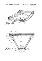
- FIG. 1 represents a simplified cross section of a CRT constructed in accordance with the invention
- FIG. 2 is a perspective view of a mask support frame constructed in accordance with the invention.
- FIG. 3A is a plan view of a prior art support frame and tensed mask assembly with an exaggerated showing of the in plane distortion experienced therein;
- FIG. 3B is a perspective view of a prior art support frame and tensed mask assembly with an exaggerated showing of the transverse distortion experienced therein;
- FIG. 4 is a partial cross section of an assembled support frame and panel, constructed in accordance with the invention, positioned at an exposure station.
- a CRT 10 includes a flat or cylindrical glass panel or faceplate 12, (here shown as flat) a glass support frame 14 constructed in accordance with the invention, and a small, generally bell-shaped funnel 15 that extends into a small-diameter cylindrical neck 16 for housing an electron gun structure (not shown) of conventional form. Funnel 15 and frame 14 are part of what is generally referred to as the envelope of the CRT 10.
- the inner surface of panel 12 has formed thereon by conventional photodeposition techniques, a target or screen 17 consisting of a pattern of red-, blue-, and green-light-emitting phosphors corresponding to the pattern of apertures in a confronting shadow mask 18 that is maintained under tension.
- the support frame 14 includes a recessed shelf for supporting tensed shadow mask 18 a predetermined distance from screen 17, which distance is generally referred to as the "Q" distance.
- the elements of the CRT are joined together by devitrifiable frit at junctions 19 and 21.
- the glass frit devitrifies at high temperature to form a glass bond between the adjoining elements during manufacture of the CRT.
- the bond at junction 21 may in the design of this support frame be formed by a flame-sealing operation; that is, a glass-to-glass melting between the lower portions of support frame 14 and the large end of funnel 15.
- the support frame 14 has a deeply elongated skirt means 30 extending rearwardly from the faceplate.
- the deep configuration of this skirt, together with the flange 22, lends stiffness to the support frame 14 to enable the frame to resist distortion by the tension in the tensed mask.
- the skirt forms a major portion of the CRT envelope.
- FIG. 2 a perspective view of the support frame 14 is shown, constructed in accordance with the invention.
- a flat seal surface 38 forms the mating edge of the support frame 14, which may include registration means (not shown in this figure).
- Displaced from seal surface 38 is a shelf 26 upon which mask 18 is supported in tension by means of a bead of glass frit 28 which surrounds the periphery of mask 18.
- the very deep skirt 30 extends axially rearwardly from flange 22 and the shelf 26, terminating in another seal surface 23 at the small end of support frame 14.
- a plurality of axial strengthening ribs 29 are disposed about the periphery of support frame 14 for strengthening the support frame 14 in resistance to pressure vessel loads imposed during tube evacuation.
- the provision of the ribs enables the support frame to be constructed of much thinner glass than would otherwise be feasible.
- strengthening ribs 29 bridge the junction of flange 22 and skirt 30 of frame 14 and, as depicted in FIG. 2, are geometrically located in the vicinity of the major and minor axes of flange 22.
- Ribs 29 will be seen to add support to an outer flange 22 of the support frame in the area of shelf 26, thus enabling the structural juncture of the flange 22 and skirt 30 to withstand the discontinuity stresses imposed on panel 12 during evacuation.
- Flange 22 will be seen as radially outwardly and axially forwardly extending from skirt 30 for joining to the periphery of panel 12.
- Shelf 26 extends radially inwardly from flange 22 and provides a support surface for the edges of the tensed mask 18. Shelf 26 is shown also as being axially offset for determining a precise spaced relationship therebetween.
- FIG. 3A a plan view, and in FIG. 3B, a perspective view, of a shallow glass support frame not having the features of the present invention, is shown to illustrate the deformation which results from the tensed mask forces exerted thereon absent a construction corresponding to frame 14.
- the forces are generally illustrated by the arrows labelled F.
- the dotted lines indicate the normal unstrained outline of the support frame.
- the inward distortion that occurs under the forces exerted by the tensed mask is shown by the solid lines, in FIG. 3A, and the "pillowing" roll, and twist distortion caused by the same forces is shown by the solid lines in FIG. 3B.
- FIG. 4 an enlarged cross section of the support frame with a tensed mask assembled in position for screening in an exposure station corresponding to a conventional lighthouse is schematically illustrated.
- Flange 22 extends into shelf 26 forming a support surface parallel to flat panel 12 for supporting tensed mask 18 by means of frit bond 28.
- Support frame 14 has a deeply elongated skirt 30 extending rearwardly away from the shelf 26, forming the major portion of the CRT envelope. Skirt 30 terminates in a seal surface 23.
- One of a plurality of spaced strengthening ribs 29 is shown extending axially from outer flange 22 to a point towards the termination of the elongated skirt 30.
- the CRT envelope is a vessel that is subject to significant pressure due to atmospheric forces.
- the support frame 14 forms a major portion of the CRT envelope, it may ideally be of relatively light-weight construction, provided suitable strengthening members are incorporated. As illustrated, ball-and-groove registration means 43 and 44 are shown as being located at the intersections of the inner surface of panel 12 and seal surface 38 of support 14, and the seal surface 23 at the small end of support frame 14 and the corresponding walls 45 on the exposure station, respectively.
- the exposure station includes a lens 40 disposed in the open end of support frame 14, a collimator tip 41, and a source of energy 42 actinic to the photosensitive screening coatings for directing rays of light to screen 17 through tensed aperture mask 18 for exposure of the photosensitive material on screen 17.
- collimator tip 41 and lens 40 cooperate to simulate electron beams emanating from the appropriate position in the neck of the CRT corresponding to one of the electron beam sources.
- support frame 14 and panel 12 are positioned in registration on different lighthouses having collimator tips, lenses and sources arranged to simulate the individual locations of each of the electron guns in the CRT.
- the CRT is frit-bonded and evacuated while being subjected to baking temperatures to complete its fabrication in accordance with conventional techniques.
- the substantial distance of screen 17 from seal surface 23 permits skirt 30 be flame-sealed to the funnel portion of the CRT if that is desired.
- the support frame construction of the invention not only does an extremely rigid, substantially non-deformable support frame for the tensed mask result, but the thickness of the skirt may be reduced significantly from that of a conventional CRT envelope of similar size and type.
- the prior-art problem of the screen being formed by exposure through the tensed mask in a distorted condition, and being operated with the tensed mask in undistorted condition is eliminated.
Abstract
Description
Claims (4)
Priority Applications (1)
| Application Number | Priority Date | Filing Date | Title |
|---|---|---|---|
| US06/735,887 US4656388A (en) | 1985-05-17 | 1985-05-17 | Tensed mask color cathode ray tube and mask support frame therefore |
Applications Claiming Priority (1)
| Application Number | Priority Date | Filing Date | Title |
|---|---|---|---|
| US06/735,887 US4656388A (en) | 1985-05-17 | 1985-05-17 | Tensed mask color cathode ray tube and mask support frame therefore |
Publications (1)
| Publication Number | Publication Date |
|---|---|
| US4656388A true US4656388A (en) | 1987-04-07 |
Family
ID=24957650
Family Applications (1)
| Application Number | Title | Priority Date | Filing Date |
|---|---|---|---|
| US06/735,887 Expired - Fee Related US4656388A (en) | 1985-05-17 | 1985-05-17 | Tensed mask color cathode ray tube and mask support frame therefore |
Country Status (1)
| Country | Link |
|---|---|
| US (1) | US4656388A (en) |
Cited By (4)
| Publication number | Priority date | Publication date | Assignee | Title |
|---|---|---|---|---|
| US4731557A (en) * | 1985-07-05 | 1988-03-15 | Hitachi, Ltd. | Liquid cooling type projection picture tube |
| US4884006A (en) * | 1986-12-30 | 1989-11-28 | Zenith Electronics Corporation | Inner surface specular reflection suppression in flat CRT faceplate |
| US5238132A (en) * | 1991-12-10 | 1993-08-24 | Nippon Sheet Glass Co., Ltd. | Glass pressure-vessel for a cathode ray tube |
| US6727640B2 (en) * | 2000-05-15 | 2004-04-27 | Matsushita Electric Industrial Co., Ltd. | Glass bulb for a cathode-ray tube and a cathode-ray tube device |
Citations (18)
| Publication number | Priority date | Publication date | Assignee | Title |
|---|---|---|---|---|
| US2761990A (en) * | 1954-02-19 | 1956-09-04 | Rauland Corp | Color television image reproducer |
| CA558694A (en) * | 1958-06-10 | De Gier Johannes | Reinforced evacuated metal vessels | |
| US3166211A (en) * | 1960-11-03 | 1965-01-19 | Philips Corp | Glass cathode ray tube for reproducing images |
| GB1026624A (en) * | 1961-11-28 | 1966-04-20 | Polymer Processes Inc | Improvements in,or relating to,protective coatings for cathode ray tubes |
| US3404302A (en) * | 1967-06-21 | 1968-10-01 | Gen Electric | Envelope wall with two continuous ledges for positioning and supporting aperture mask |
| US3440469A (en) * | 1966-09-01 | 1969-04-22 | Georges Bradu | Flat screen attachment inside cathoderay tube by snap ring and clip assembly |
| GB1163495A (en) * | 1966-06-23 | 1969-09-04 | Saint Gobain | Improvements in or relating to Cathode-Ray Tubes |
| DE2122948A1 (en) * | 1969-08-21 | 1971-12-16 | Philips Nv | Method for attaching a tension band around the piston of a television picture tube and picture tube provided with a tension band by this method |
| US3638063A (en) * | 1968-01-11 | 1972-01-25 | Sony Corp | Grid structure for color picture tubes |
| US3720345A (en) * | 1970-06-08 | 1973-03-13 | Owens Illinois Inc | Television bulb with improved strength |
| US3873874A (en) * | 1974-02-20 | 1975-03-25 | Gte Sylvania Inc | Shield attached by sealing to panel sidewall of cathode ray tube |
| US3894321A (en) * | 1974-01-24 | 1975-07-15 | Zenith Radio Corp | Method for processing a color cathode ray tube having a thin foil mask sealed directly to the bulb |
| US4037255A (en) * | 1975-12-11 | 1977-07-19 | Zenith Radio Corporation | Implosion protection system for color CRT bulb having a bonded funnel frame |
| US4069567A (en) * | 1977-02-28 | 1978-01-24 | Zenith Radio Corporation | Method of installing a color selection electrode in a color cathode ray tube |
| US4169274A (en) * | 1978-03-27 | 1979-09-25 | Gte Sylvania Incorporated | Implosion resistant cathode ray tube |
| US4432464A (en) * | 1981-09-09 | 1984-02-21 | Thomas Electronics, Inc. | Large metal cone cathode ray tubes, and envelopes therefor |
| US4461971A (en) * | 1982-08-04 | 1984-07-24 | North American Philips Consumer Electronics Corp. | Strengthening means for a CRT multi-opening mask framing member |
| US4495437A (en) * | 1981-08-26 | 1985-01-22 | Sony Corporation | Grid apparatus for use with a color cathode ray tube |
-
1985
- 1985-05-17 US US06/735,887 patent/US4656388A/en not_active Expired - Fee Related
Patent Citations (18)
| Publication number | Priority date | Publication date | Assignee | Title |
|---|---|---|---|---|
| CA558694A (en) * | 1958-06-10 | De Gier Johannes | Reinforced evacuated metal vessels | |
| US2761990A (en) * | 1954-02-19 | 1956-09-04 | Rauland Corp | Color television image reproducer |
| US3166211A (en) * | 1960-11-03 | 1965-01-19 | Philips Corp | Glass cathode ray tube for reproducing images |
| GB1026624A (en) * | 1961-11-28 | 1966-04-20 | Polymer Processes Inc | Improvements in,or relating to,protective coatings for cathode ray tubes |
| GB1163495A (en) * | 1966-06-23 | 1969-09-04 | Saint Gobain | Improvements in or relating to Cathode-Ray Tubes |
| US3440469A (en) * | 1966-09-01 | 1969-04-22 | Georges Bradu | Flat screen attachment inside cathoderay tube by snap ring and clip assembly |
| US3404302A (en) * | 1967-06-21 | 1968-10-01 | Gen Electric | Envelope wall with two continuous ledges for positioning and supporting aperture mask |
| US3638063A (en) * | 1968-01-11 | 1972-01-25 | Sony Corp | Grid structure for color picture tubes |
| DE2122948A1 (en) * | 1969-08-21 | 1971-12-16 | Philips Nv | Method for attaching a tension band around the piston of a television picture tube and picture tube provided with a tension band by this method |
| US3720345A (en) * | 1970-06-08 | 1973-03-13 | Owens Illinois Inc | Television bulb with improved strength |
| US3894321A (en) * | 1974-01-24 | 1975-07-15 | Zenith Radio Corp | Method for processing a color cathode ray tube having a thin foil mask sealed directly to the bulb |
| US3873874A (en) * | 1974-02-20 | 1975-03-25 | Gte Sylvania Inc | Shield attached by sealing to panel sidewall of cathode ray tube |
| US4037255A (en) * | 1975-12-11 | 1977-07-19 | Zenith Radio Corporation | Implosion protection system for color CRT bulb having a bonded funnel frame |
| US4069567A (en) * | 1977-02-28 | 1978-01-24 | Zenith Radio Corporation | Method of installing a color selection electrode in a color cathode ray tube |
| US4169274A (en) * | 1978-03-27 | 1979-09-25 | Gte Sylvania Incorporated | Implosion resistant cathode ray tube |
| US4495437A (en) * | 1981-08-26 | 1985-01-22 | Sony Corporation | Grid apparatus for use with a color cathode ray tube |
| US4432464A (en) * | 1981-09-09 | 1984-02-21 | Thomas Electronics, Inc. | Large metal cone cathode ray tubes, and envelopes therefor |
| US4461971A (en) * | 1982-08-04 | 1984-07-24 | North American Philips Consumer Electronics Corp. | Strengthening means for a CRT multi-opening mask framing member |
Cited By (4)
| Publication number | Priority date | Publication date | Assignee | Title |
|---|---|---|---|---|
| US4731557A (en) * | 1985-07-05 | 1988-03-15 | Hitachi, Ltd. | Liquid cooling type projection picture tube |
| US4884006A (en) * | 1986-12-30 | 1989-11-28 | Zenith Electronics Corporation | Inner surface specular reflection suppression in flat CRT faceplate |
| US5238132A (en) * | 1991-12-10 | 1993-08-24 | Nippon Sheet Glass Co., Ltd. | Glass pressure-vessel for a cathode ray tube |
| US6727640B2 (en) * | 2000-05-15 | 2004-04-27 | Matsushita Electric Industrial Co., Ltd. | Glass bulb for a cathode-ray tube and a cathode-ray tube device |
Similar Documents
| Publication | Publication Date | Title |
|---|---|---|
| US4547696A (en) | Tension mask registration and supporting system | |
| CA1220507A (en) | Flat square cathode ray tube | |
| US2897392A (en) | Color television tube mask and frame assembly | |
| US2846608A (en) | Cathode-ray tube | |
| US4686415A (en) | Tensed mask color cathode ray tube and mask support frame therefor | |
| US4591344A (en) | Method of fabricating a tension mask color cathode ray tube | |
| EP0278709B1 (en) | Cathode ray-tube having shadow mask for low overscan | |
| US4656388A (en) | Tensed mask color cathode ray tube and mask support frame therefore | |
| US4593225A (en) | Tension mask colar cathode ray tube | |
| US4656389A (en) | Tensed mask cathode ray tube | |
| US4614892A (en) | Tension mask mounting structure | |
| US4678447A (en) | Process of manufacturing for a high-resolution color cathode ray tube | |
| US2903319A (en) | Image reproduction device | |
| JPH05198277A (en) | Cathode-ray tube and method of forming interference-fitted implosion protective band | |
| US4721879A (en) | Tensed mask cathode ray tube | |
| US4672260A (en) | Registration-enhancing means and method for color cathode ray tubes having the tensed foil shadow mask | |
| EP0211963B1 (en) | Color cathode ray tube and component thereof and method of manufacturing same | |
| US4695523A (en) | Method of screening a flat mask cathode ray tube | |
| TW385472B (en) | Cathode-ray tube and manufacturing the same | |
| US4891548A (en) | Tension mask color cathode ray tube component with external registration-affording means | |
| US4723089A (en) | Removable screening mount for a tensed mask cathode ray tube | |
| US3733976A (en) | Intermediate sub-assembly for use in making color picture tubes | |
| JP3264964B2 (en) | Manufacturing method of cathode ray tube | |
| US5030154A (en) | Method of mounting tensed CRT mask | |
| JP3090703B2 (en) | Picture tube manufacturing method |
Legal Events
| Date | Code | Title | Description |
|---|---|---|---|
| AS | Assignment |
Owner name: ZENITH ELECTRONICS CORPORATION, 1000 MILWAUKEE AVE Free format text: ASSIGNMENT OF ASSIGNORS INTEREST.;ASSIGNOR:STRAUSS, PAUL;REEL/FRAME:004652/0439 Effective date: 19850516 Owner name: ZENITH ELECTRONICS CORPORATION, ILLINOIS Free format text: ASSIGNMENT OF ASSIGNORS INTEREST;ASSIGNOR:STRAUSS, PAUL;REEL/FRAME:004652/0439 Effective date: 19850516 |
|
| FEPP | Fee payment procedure |
Free format text: PAYOR NUMBER ASSIGNED (ORIGINAL EVENT CODE: ASPN); ENTITY STATUS OF PATENT OWNER: LARGE ENTITY |
|
| FPAY | Fee payment |
Year of fee payment: 4 |
|
| AS | Assignment |
Owner name: FIRST NATIONAL BANK OF CHICAGO, THE Free format text: SECURITY INTEREST;ASSIGNOR:ZENITH ELECTRONICS CORPORATION A CORP. OF DELAWARE;REEL/FRAME:006187/0650 Effective date: 19920619 |
|
| AS | Assignment |
Owner name: ZENITH ELECTRONICS CORPORATION Free format text: RELEASED BY SECURED PARTY;ASSIGNOR:FIRST NATIONAL BANK OF CHICAGO, THE (AS COLLATERAL AGENT).;REEL/FRAME:006243/0013 Effective date: 19920827 |
|
| REMI | Maintenance fee reminder mailed | ||
| LAPS | Lapse for failure to pay maintenance fees | ||
| FP | Lapsed due to failure to pay maintenance fee |
Effective date: 19950412 |
|
| STCH | Information on status: patent discontinuation |
Free format text: PATENT EXPIRED DUE TO NONPAYMENT OF MAINTENANCE FEES UNDER 37 CFR 1.362 |