EP1156243A1 - Flow control valve - Google Patents
Flow control valve Download PDFInfo
- Publication number
- EP1156243A1 EP1156243A1 EP00979034A EP00979034A EP1156243A1 EP 1156243 A1 EP1156243 A1 EP 1156243A1 EP 00979034 A EP00979034 A EP 00979034A EP 00979034 A EP00979034 A EP 00979034A EP 1156243 A1 EP1156243 A1 EP 1156243A1
- Authority
- EP
- European Patent Office
- Prior art keywords
- hot water
- valve
- valve body
- flow path
- heat exchanger
- Prior art date
- Legal status (The legal status is an assumption and is not a legal conclusion. Google has not performed a legal analysis and makes no representation as to the accuracy of the status listed.)
- Granted
Links
Images





Classifications
-
- F—MECHANICAL ENGINEERING; LIGHTING; HEATING; WEAPONS; BLASTING
- F16—ENGINEERING ELEMENTS AND UNITS; GENERAL MEASURES FOR PRODUCING AND MAINTAINING EFFECTIVE FUNCTIONING OF MACHINES OR INSTALLATIONS; THERMAL INSULATION IN GENERAL
- F16K—VALVES; TAPS; COCKS; ACTUATING-FLOATS; DEVICES FOR VENTING OR AERATING
- F16K5/00—Plug valves; Taps or cocks comprising only cut-off apparatus having at least one of the sealing faces shaped as a more or less complete surface of a solid of revolution, the opening and closing movement being predominantly rotary
- F16K5/04—Plug valves; Taps or cocks comprising only cut-off apparatus having at least one of the sealing faces shaped as a more or less complete surface of a solid of revolution, the opening and closing movement being predominantly rotary with plugs having cylindrical surfaces; Packings therefor
- F16K5/0457—Packings
- F16K5/0464—Packings in the housing
Definitions
- the present invention relates to a flow control valve provided in a hot water circuit of a vehicle heater for switching a flow path for hot water.
- a flow control valve 50 as shown in Fig. 12 has been known.
- the valve is provided in a hot water circuit of a vehicle heater for adjusting a flow rate of hot water.
- a hot water inlet pipe 52 and a hot water outlet pipe 53 are formed in a valve housing 51, in which a valve body 54 is accommodated.
- a flow rate of the hot water to be fed to a heat exchanger for a heater (heater core) via the hot water outlet pipe 53 is adjusted by rotating the valve body 54 to open/close the hot water circuit.
- a packing 55 for sealing the valve body 54 is provided at an upstream end of the hot water outlet pipe 53 and is biased by a plate spring 56 to be in tight contact with the valve body 54.
- Two ribs 57 are formed in a contact surface of the valve body 54 to provide a gap 58 between the valve body 54 and the valve housing 51.
- the hot water dwells in the valve housing 51 when the hot water outlet pipe 53 is fully open (at a position where the valve body is rotated by approximately 90 degrees from a position shown in Fig. 12(b)) whereby the foreign matters are liable to be left in the interior of the valve housing 51.
- the valve body 54 is frequently rotated to repeat the flow rate adjustment under such circumstances, there is a probability in that the foreign matters may get into between the valve housing 51 and the valve body 54 to impair a rotor surface of the valve body 54. If the rotor surface of the valve body 54 is impaired, there would be a problem in that a gap is generated between the valve body 54 and the packing 55 to deteriorate the sealability.
- the present invention has been made in view of the above problems in the prior art, and an object thereof is to maintain a sealability between a valve body and a valve housing in a flow control valve provided in a hot water circuit by preventing foreign matter from entering the interior of the valve housing.
- part of the hot water supplied to the valve through an inlet flow path is directed to a bypass side outlet flow path via a communication path for communicating a control flow path with the bypass side outlet flow path when the opening degree of the bypass side outlet flow path is minimum, whereby even if foreign matters contained in the hot water flow into the interior of the valve housing, they could always be excluded therefrom to the bypass side outlet flow path.
- a communication path for communicating a control flow path with the bypass side outlet flow path when the opening degree of the bypass side outlet flow path is minimum
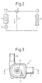
- reference numeral 1 denotes a water-cooled type car engine (a hot water source) and 2 denotes a water pump driven by the engine 1 to circulate water through a cooling water circuit (hot water circuit) of the engine 1.
- Reference numeral 3 denotes a heat exchanger for a heater (heat core) for heat-exchanging between hot water fed from the engine 1 and air to heat the air, and 4 denotes a flow control valve according to the present invention having a structure of a three-way valve type with three paths for hot water.
- a bypass circuit 5 is provided parallel to the heat exchanger 3 so that the hot water can return while bypassing the heat exchanger 3.
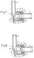
- Reference numeral 6 denotes a valve body molded in a cylindrical form with a resinous material excellent both in heat resistance and moldability.
- the valve body 6 is disposed and accommodated in a rotatable manner within the interior of a valve housing 7 formed, of a resin excellent both in heat resistance and moldability, into a generally tubular form.
- a hot water inlet pipe 8 (inlet side flow path), molded with the resin integrally therewith, through which hot water enters the valve housing 7 from the engine 1.
- a first hot water outlet pipe 9 heat exchanger side outlet flow path
- a second hot water outlet pipe 10 bypass side outlet flow path
- an upstream portion of the first hot water outlet pipe 9 is of a form projected into the valve body 6.
- An upstream end opening 11 of the second hot water inlet pipe 10 is defined at a position deviated from an axial center of the first hot water outlet pipe 8.
- Control flow paths 12a, 12b are provided in the cylindrical valve body 6 for regulating opening areas of the respective pipes 9 and 10 with a predetermined correlation.
- Reference numeral 13 denotes a shaft coupled to the valve body 6 integrally therewith for rotationally operating the valve body 6. This shaft 13 is fitted into a through-hole 15 formed in an upper cover 14 for the valve housing 7 to project out of the upper cover 14. A projected end of the shaft 13 is coupled to an actuator such as a motor or the like via a lever, not shown, to be rotatable thereby. In this regard, the shaft 13 may be manually rotated.
- An O-ring 16 is disposed in an annular groove 15a formed along the inner peripheral wall of the through-hole 15 for the purpose of sealing.
- Reference numeral 17 is a hollow tubular seal member formed of a rubber-like material excellent in heat resistance, such as nitro-butadiene rubber, one end 171 of which is brought into tight contact and fitted with the outer periphery of the hot water outlet pipe 9 projected into the valve body 6 to seal the same.
- the outer periphery of the fitted portion of the seal member 17 is fastened with a wire.
- the other end 172 of the seal member 17 is larger than the one end 171 as seen in the radial direction.
- An annular convex portion is projected from the inner wall of the other end 172 of the seal member 17 and brought into tight contact with the periphery of the control flow path 12a of the valve body. Further, a front area of the other end 172 of the seal member 17 is in tight contact with the periphery of the control flow path 12a solely in the axial direction of the valve body 6.
- a plate spring 18 is a rectangular member of anti-corrosive spring material such as stainless steel, which is bent at opposite ends and has a hole (not shown) in a middle portion thereof.
- the valve body 6 is disposed so that the bent ends of the plate spring 18 are held by a shoulder 7b formed in the valve housing 7 and the seal member 17 is fitted into the hole of the plate spring 18, whereby the elastic force of the plate spring 18 is applied to the other end 172 of the seal member 17 to cause the other end 172 of the seal member 17 to be in tight contact with the valve body 6.
- the valve body 6 is brought into tight contact with the seal member 17 and held in a rotatable manner.
- the plate spring 18 has an elastic force as small as possible, provided the press-contact of the other end 172 of the seal member 17 with the valve body 6 can be maintained, the valve body 6 is smoothly rotatable.
- a seat surface 19 having a predetermined height h1 (for example, 0.8 mm) is defined on the periphery of the opening 11 in an inner wall 7a of the valve housing 7.
- Ribs 20, 21 are formed on the seat surface 19.
- a rib 22 is formed at a position symmetrical with the rib 21 relative to an axis of the second hot water outlet pipe 9 in the inner wall 7a of the valve housing 7, so that a load of the valve body 6 biased with the plate spring 18 is equally applied to the ribs 21 and 22.
- These ribs 20 to 22 have a height h2 from the inner wall 7a of the valve housing 7, and the valve body 6 is held to define a gap A between the same and the inner wall 7a of the valve housing 7.
- the ribs 20, 21 are partially formed in the axial direction of the valve body 6, and a part of the inner wall 7a of the valve housing 7, wherein the ribs 20, 21 are not formed, has a height h1 of the seat surface 19 relative to the inner wall 7a of the valve housing 7.
- a gap B is defined between the valve body 6 and the part wherein the rib 20 is not formed.
- the second hot water outlet pipe 10 when the second hot water outlet pipe 10 is at the minimum opening degree, it is communicated with the gap A and the control flow path 12b via the gap B operative as a communication path.
- a further gap is similarly defined between the valve body 6 and a part wherein the rib 21 is not formed.
- the second hot water outlet pipe 10 is communicated with a space lower than the valve body 6 and a gap C via the further gap operative as a communication path.
- the gap B has a height h3 which is a difference between the height h2 of the rib 20 and the height h1 of the seat surface 19.
- the flow control valve 4 opens or closes the control flow paths 12a, 12b by the rotation of the valve body 6 about the shaft 13 to regulate a flow rate of hot water into the heat exchanger 3 so that a heating capacity of the car heater is controlled.
- valve body 6 when the heater is not operated (or when the cooler is operated at the maximum capacity in a refrigeration cycle mode in a car air-conditioner provided with a cooling evaporator), the valve body 6 is made to rotate to a position shown in Fig. 8 so that the control flow path 12b fully opens. At this time, the control flow path 12a fully closes so that all the hot water flowing into the valve via the hot water inlet pipe 8 flows out to the second hot water outlet pipe 10, eventually all the hot water flows out to the bypass circuit 5, and the hot water flowing to the heat exchanger 3 is interrupted.
- valve body 6 when the heater is operated at the maximum capacity, the valve body 6 is made to rotate to a position shown in Fig. 7 to open the control flow path 12a so that the hot water from the hot water inlet pipe 8 flows out to the first outlet pipe 9.
- the control flow path 12b is at a position opposed to the inner wall 7a of the valve housing 7 and in a fully closed state (wherein the opening degree is minimum).
- the second hot water outlet pipe 10 is communicated with the control flow path 12b via the gap B when the heater is operated at the maximum capacity. Accordingly, part of the hot water from the hot water inlet pipe 8 flows out via the gap B to the hot water outlet pipe 10.
- the second hot water outlet pipe 10 When the heater is operated at the maximum capacity, the second hot water outlet pipe 10 is communicated with the gap C via the gap B. Since a lower space of the valve body 6 to which the hot water inlet pipe 8 is connected, communicates with the gap C, part of the hot water from the hot water inlet pipe 8 flows out via the gaps C and B to the second hot water outlet pipe 10.
- valve body 6 when the valve body 6 is small in diameter to minimize a valve size, it is possible to reduce the leakage of the hot water to the first hot water outlet pipe 9 when the valve body 6 rotates, by providing the rib 21 having the gap B in an area of the inner wall of the valve housing 7 wherein part of the valve body 6 to be sealed with the seal member 17 rotates when the heater is not operated.
- the leakage of the hot water to the bypass circuit 5 can be suppressed to a level in correspondence to a flow rate wherein the lowering of the heating capacity of the heat exchanger 3 is approximately 10% or less by determining the height h3 of the gap B at 0.5 mm or less.
- the gap is preferably 0.2 mm or more in view of the manufacturing process.
- the first hot water outlet pipe 9 and the second hot water outlet pipe 10 may coincide with each other as shown in Fig. 11 wherein the same reference numerals are used for denoting the same elements as in the first embodiment and the detailed description thereof will be eliminated.
- Two ribs 24, 25 are formed in the inner wall of a valve housing 23, and a valve body 6 is held so that a gap 26 is provided between the valve housing 23 and the valve body 6.
Landscapes
- Engineering & Computer Science (AREA)
- General Engineering & Computer Science (AREA)
- Mechanical Engineering (AREA)
- Taps Or Cocks (AREA)
- Multiple-Way Valves (AREA)
- Air-Conditioning For Vehicles (AREA)
- Sliding Valves (AREA)
Abstract
Description
Claims (4)
- A flow control valve provided in a hot water circuit comprising a hot water source, a heat exchanger for heating air by exchanging heat between hot water supplied from the hot water source and the air, and a bypass circuit for bypassing the heat exchanger, for regulating a flow rate of the hot water supplied from the hot water source to the heat exchanger and to the bypass circuit, characterized in thatthe flow control valve comprises a valve housing having an inlet flow path for supplying the hot water from the hot water source into the valve, a heat exchanger side outlet flow path for directing the hot water supplied into the valve through the inlet flow path to the heat exchanger, and a bypass side outlet flow path for directing the hot water supplied into the valve through the inlet flow path to the bypass circuit,a valve body provided in the interior of the valve housing in a rotatable manner for opening/closing the heat exchanger side outlet flow path and the bypass side outlet flow path,a control flow path formed in the valve body for regulating an open area of the heat exchanger side outlet flow path and the bypass side outlet flow path,ribs projected from the inner wall of the valve housing for supporting the valve body, anda communication path formed in at least part of the ribs for directing part of the hot water supplied into the valve through the inlet flow path to the bypass side outlet flow path when the opening degree of the bypass side outlet flow path is minimum.
- A flow control valve as defined by claim 1, characterized in that a seat surface is formed on the periphery of an opening defining the upstream end of the bypass side outlet flow path in the inner wall of the valve housing, with a predetermined gap from the valve body, and the communication path is a gap between the seat surface and the valve body, and in that the gap between the seat surface and the valve body is smaller than a gap between the valve body and the valve housing.
- A flow control valve as defined by claim 1 or 2, characterized in that the gap of the communication path is 0.2 mm or more and 0.5 mm or less.
- A flow control valve as defined by any one of claims 1 to 3, characterized in that a seal member for sealing the valve body from the interior of the valve housing is provided on the periphery of the heat exchanger side flow path, and in that the ribs are formed at a position opposed to a portion of the valve body to be sealed with the seal member when the heat exchanger side outlet flow path is closed.
Applications Claiming Priority (3)
| Application Number | Priority Date | Filing Date | Title |
|---|---|---|---|
| JP34060099 | 1999-11-30 | ||
| JP34060099A JP4081946B2 (en) | 1999-11-30 | 1999-11-30 | Flow control valve |
| PCT/JP2000/008480 WO2001040687A1 (en) | 1999-11-30 | 2000-11-30 | Flow control valve |
Publications (3)
| Publication Number | Publication Date |
|---|---|
| EP1156243A1 true EP1156243A1 (en) | 2001-11-21 |
| EP1156243A4 EP1156243A4 (en) | 2002-04-10 |
| EP1156243B1 EP1156243B1 (en) | 2007-10-24 |
Family
ID=18338544
Family Applications (1)
| Application Number | Title | Priority Date | Filing Date |
|---|---|---|---|
| EP00979034A Expired - Lifetime EP1156243B1 (en) | 1999-11-30 | 2000-11-30 | Flow control valve |
Country Status (4)
| Country | Link |
|---|---|
| EP (1) | EP1156243B1 (en) |
| JP (1) | JP4081946B2 (en) |
| DE (1) | DE60036860T2 (en) |
| WO (1) | WO2001040687A1 (en) |
Cited By (3)
| Publication number | Priority date | Publication date | Assignee | Title |
|---|---|---|---|---|
| WO2007051825A1 (en) * | 2005-11-04 | 2007-05-10 | Valeo Systemes Thermiques | Improved sealed control valve for a fluid flow circuit |
| CN103032604A (en) * | 2011-09-30 | 2013-04-10 | 株式会社能率 | Valve apparatus and water heating apparatus |
| WO2015091773A1 (en) * | 2013-12-19 | 2015-06-25 | Valeo Systemes Thermiques | Control valve with stepped sealing segment |
Families Citing this family (15)
| Publication number | Priority date | Publication date | Assignee | Title |
|---|---|---|---|---|
| FR2827357B1 (en) * | 2001-07-11 | 2003-12-12 | Valeo Thermique Moteur Sa | CONTROL VALVE FOR A FLUID CIRCUIT, PARTICULARLY FOR AN ENGINE COOLING CIRCUIT |
| FR2827360B1 (en) | 2001-07-11 | 2005-10-28 | Valeo Thermique Moteur Sa | CONTROL VALVE FOR A FLUID CIRCUIT CIRCUIT, ESPECIALLY FOR A COOLING CIRCUIT OF AN ENGINE |
| JP4082941B2 (en) * | 2002-06-28 | 2008-04-30 | 大阪瓦斯株式会社 | Three-way valve |
| JP4774968B2 (en) * | 2005-12-09 | 2011-09-21 | パナソニック電工株式会社 | Flow control valve |
| KR101180041B1 (en) | 2006-10-31 | 2012-09-05 | 한라공조주식회사 | Heater Core And Air conditioner for an Automobile equipped with same |
| JP2009180240A (en) * | 2008-01-29 | 2009-08-13 | Denso Corp | Flow control valve |
| JP2011117614A (en) * | 2011-03-17 | 2011-06-16 | Panasonic Electric Works Co Ltd | Passage control valve |
| JP5938902B2 (en) * | 2011-12-28 | 2016-06-22 | 株式会社ノーリツ | Valve device and hot water supply device |
| JP5914176B2 (en) | 2012-05-31 | 2016-05-11 | 株式会社ミクニ | Rotary valve |
| JP6076235B2 (en) * | 2013-11-15 | 2017-02-08 | 日立オートモティブシステムズ株式会社 | Flow control valve |
| US10280829B2 (en) * | 2015-06-05 | 2019-05-07 | Hitachi Automotive Systems, Ltd. | Flow rate control valve |
| JP2017166569A (en) * | 2016-03-16 | 2017-09-21 | 日立オートモティブシステムズ株式会社 | Flow control valve and cooling system |
| TWI660135B (en) * | 2018-05-14 | 2019-05-21 | 訊凱國際股份有限公司 | Control valve |
| JP7109523B2 (en) * | 2020-11-27 | 2022-07-29 | 日立Astemo株式会社 | Flow control valve and cooling system |
| DE102021133871A1 (en) * | 2021-12-20 | 2023-06-22 | Vr Automotive Dichtungssysteme Gmbh | METHOD OF MAKING A GASKET, GASKET AND USE OF A GASKET MADE BY SUCH METHOD |
Family Cites Families (12)
| Publication number | Priority date | Publication date | Assignee | Title |
|---|---|---|---|---|
| US2483722A (en) * | 1945-05-02 | 1949-10-04 | Bennett Vivian Ray | Oxygen valve |
| JPS59118855U (en) * | 1983-01-31 | 1984-08-10 | 株式会社デンソー | flow regulating valve |
| JPS59125660U (en) * | 1983-02-15 | 1984-08-24 | 株式会社デンソー | flow regulating valve |
| US4700928A (en) * | 1986-10-31 | 1987-10-20 | Masco Corporation Of Indiana | Valve assembly |
| US4778152A (en) * | 1987-05-19 | 1988-10-18 | Mueller Co. | Plug valve havig interchangeable plug member |
| JP2661081B2 (en) * | 1987-12-11 | 1997-10-08 | 株式会社デンソー | Flow open / close valve |
| JPH05172261A (en) * | 1991-12-26 | 1993-07-09 | Sanyo Electric Co Ltd | Flow path selector valve |
| JP3279105B2 (en) * | 1994-12-27 | 2002-04-30 | 株式会社デンソー | Flow control valve and hot water heating system using the same |
| DE4431711A1 (en) * | 1994-09-06 | 1996-03-07 | Bosch Gmbh Robert | Device for regulating the idle speed of an internal combustion engine |
| JP3627327B2 (en) * | 1995-12-13 | 2005-03-09 | 株式会社デンソー | Flow control valve and hot water heater using the same |
| JPH10132097A (en) * | 1996-10-29 | 1998-05-22 | Denso Corp | Flow control valve |
| US5871032A (en) * | 1997-08-01 | 1999-02-16 | Chung Cheng Faucet Co., Ltd. | Diverter valve assembly for control of multiple discharge in a mixing faucet |
-
1999
- 1999-11-30 JP JP34060099A patent/JP4081946B2/en not_active Expired - Fee Related
-
2000
- 2000-11-30 WO PCT/JP2000/008480 patent/WO2001040687A1/en not_active Ceased
- 2000-11-30 DE DE60036860T patent/DE60036860T2/en not_active Expired - Lifetime
- 2000-11-30 EP EP00979034A patent/EP1156243B1/en not_active Expired - Lifetime
Cited By (7)
| Publication number | Priority date | Publication date | Assignee | Title |
|---|---|---|---|---|
| WO2007051825A1 (en) * | 2005-11-04 | 2007-05-10 | Valeo Systemes Thermiques | Improved sealed control valve for a fluid flow circuit |
| FR2893113A1 (en) * | 2005-11-04 | 2007-05-11 | Valeo Systemes Thermiques | ENHANCED SEAL CONTROL VALVE FOR FLUID CIRCULATION CIRCUIT |
| US8347831B2 (en) | 2005-11-04 | 2013-01-08 | Valeo Systemes Thermiquest | Sealed control valve for a fluid flow circuit |
| CN103032604A (en) * | 2011-09-30 | 2013-04-10 | 株式会社能率 | Valve apparatus and water heating apparatus |
| CN103032604B (en) * | 2011-09-30 | 2016-06-22 | 株式会社能率 | Valve gear and hot-water supply |
| WO2015091773A1 (en) * | 2013-12-19 | 2015-06-25 | Valeo Systemes Thermiques | Control valve with stepped sealing segment |
| FR3015621A1 (en) * | 2013-12-19 | 2015-06-26 | Valeo Systemes Thermiques | CONTROL VALVE WITH STAIR SEAL SEGMENT |
Also Published As
| Publication number | Publication date |
|---|---|
| EP1156243B1 (en) | 2007-10-24 |
| DE60036860T2 (en) | 2008-08-14 |
| EP1156243A4 (en) | 2002-04-10 |
| WO2001040687A1 (en) | 2001-06-07 |
| JP4081946B2 (en) | 2008-04-30 |
| DE60036860D1 (en) | 2007-12-06 |
| JP2001159471A (en) | 2001-06-12 |
Similar Documents
| Publication | Publication Date | Title |
|---|---|---|
| EP1156243A1 (en) | Flow control valve | |
| CN102047014B (en) | Flow path selector valve | |
| US11105430B2 (en) | Control valve | |
| CZ300519B6 (en) | Valve for controlling volume flows in heating and cooling system of motor vehicle | |
| US11098808B2 (en) | Control valve | |
| MXPA00010942A (en) | Seal for plug valve. | |
| KR20220145900A (en) | Variable cylinder wall for sealing of plug valves | |
| US7367544B2 (en) | Apparatus and method for replacing existing actuator zone valves in an HVAC system with a ball valve | |
| US5531248A (en) | Butterfly valve | |
| US20230050115A1 (en) | Valve device | |
| CA2128401C (en) | Butterfly valve assembly | |
| US6109534A (en) | Hot water-type heating device | |
| US9205720B2 (en) | Flow control valve and air conditioner for an automobile equipped with same | |
| WO2001014773A1 (en) | Water shut-off device for controlling a heating system for a motor vehicle | |
| JP6875012B2 (en) | Flow control valve | |
| US20210108731A1 (en) | Valve assembly and seal member applied to the valve assembly | |
| CN113167393A (en) | Control valve | |
| US20210291621A1 (en) | Control valve | |
| KR102292754B1 (en) | Ball valve | |
| JP3753228B2 (en) | Flow control valve with water stop function | |
| JP4048616B2 (en) | Flow control valve | |
| JP3603408B2 (en) | Air conditioner | |
| JP4135271B2 (en) | Pressure responsive valve in engine coolant circuit | |
| CN112879596B (en) | Rotary switching valve and refrigeration cycle system | |
| KR100341941B1 (en) | A water valve assembly in heater core of air conditioning system for vehicle |
Legal Events
| Date | Code | Title | Description |
|---|---|---|---|
| PUAI | Public reference made under article 153(3) epc to a published international application that has entered the european phase |
Free format text: ORIGINAL CODE: 0009012 |
|
| 17P | Request for examination filed |
Effective date: 20010724 |
|
| AK | Designated contracting states |
Kind code of ref document: A1 Designated state(s): AT BE CH CY DE DK ES FI FR GB GR IE IT LI LU MC NL PT SE TR |
|
| A4 | Supplementary search report drawn up and despatched |
Effective date: 20020225 |
|
| AK | Designated contracting states |
Kind code of ref document: A4 Designated state(s): AT BE CH CY DE DK ES FI FR GB GR IE IT LI LU MC NL PT SE TR |
|
| RIC1 | Information provided on ipc code assigned before grant |
Free format text: 7F 16K 5/04 A, 7F 16K 11/085 B |
|
| 17Q | First examination report despatched |
Effective date: 20020730 |
|
| RBV | Designated contracting states (corrected) |
Designated state(s): DE FR |
|
| GRAP | Despatch of communication of intention to grant a patent |
Free format text: ORIGINAL CODE: EPIDOSNIGR1 |
|
| GRAS | Grant fee paid |
Free format text: ORIGINAL CODE: EPIDOSNIGR3 |
|
| GRAA | (expected) grant |
Free format text: ORIGINAL CODE: 0009210 |
|
| AK | Designated contracting states |
Kind code of ref document: B1 Designated state(s): DE FR |
|
| REF | Corresponds to: |
Ref document number: 60036860 Country of ref document: DE Date of ref document: 20071206 Kind code of ref document: P |
|
| ET | Fr: translation filed | ||
| PLBE | No opposition filed within time limit |
Free format text: ORIGINAL CODE: 0009261 |
|
| STAA | Information on the status of an ep patent application or granted ep patent |
Free format text: STATUS: NO OPPOSITION FILED WITHIN TIME LIMIT |
|
| 26N | No opposition filed |
Effective date: 20080725 |
|
| PGFP | Annual fee paid to national office [announced via postgrant information from national office to epo] |
Ref country code: FR Payment date: 20101123 Year of fee payment: 11 |
|
| PGFP | Annual fee paid to national office [announced via postgrant information from national office to epo] |
Ref country code: DE Payment date: 20101124 Year of fee payment: 11 |
|
| REG | Reference to a national code |
Ref country code: FR Ref legal event code: ST Effective date: 20120731 |
|
| REG | Reference to a national code |
Ref country code: DE Ref legal event code: R119 Ref document number: 60036860 Country of ref document: DE Effective date: 20120601 |
|
| PG25 | Lapsed in a contracting state [announced via postgrant information from national office to epo] |
Ref country code: FR Free format text: LAPSE BECAUSE OF NON-PAYMENT OF DUE FEES Effective date: 20111130 |
|
| PG25 | Lapsed in a contracting state [announced via postgrant information from national office to epo] |
Ref country code: DE Free format text: LAPSE BECAUSE OF NON-PAYMENT OF DUE FEES Effective date: 20120601 |