EP1156196A2 - Catalyst carrier for exhaust gas purification system and method for producing same - Google Patents
Catalyst carrier for exhaust gas purification system and method for producing same Download PDFInfo
- Publication number
- EP1156196A2 EP1156196A2 EP01301035A EP01301035A EP1156196A2 EP 1156196 A2 EP1156196 A2 EP 1156196A2 EP 01301035 A EP01301035 A EP 01301035A EP 01301035 A EP01301035 A EP 01301035A EP 1156196 A2 EP1156196 A2 EP 1156196A2
- Authority
- EP
- European Patent Office
- Prior art keywords
- sheets
- assistants
- bonding
- sheet
- width
- Prior art date
- Legal status (The legal status is an assumption and is not a legal conclusion. Google has not performed a legal analysis and makes no representation as to the accuracy of the status listed.)
- Granted
Links
- 239000003054 catalyst Substances 0.000 title claims abstract description 81
- 238000000746 purification Methods 0.000 title claims abstract description 10
- 238000004519 manufacturing process Methods 0.000 title claims description 10
- 238000009792 diffusion process Methods 0.000 claims abstract description 46
- 239000010935 stainless steel Substances 0.000 claims description 22
- 229910001220 stainless steel Inorganic materials 0.000 claims description 22
- 238000004804 winding Methods 0.000 claims description 18
- 229910052782 aluminium Inorganic materials 0.000 claims description 15
- XAGFODPZIPBFFR-UHFFFAOYSA-N aluminium Chemical compound [Al] XAGFODPZIPBFFR-UHFFFAOYSA-N 0.000 claims description 15
- 230000008646 thermal stress Effects 0.000 claims description 15
- 239000000463 material Substances 0.000 claims description 13
- 238000010438 heat treatment Methods 0.000 claims description 3
- 238000000034 method Methods 0.000 abstract description 22
- 239000007789 gas Substances 0.000 description 21
- 230000008569 process Effects 0.000 description 17
- 230000003647 oxidation Effects 0.000 description 11
- 238000007254 oxidation reaction Methods 0.000 description 11
- PNEYBMLMFCGWSK-UHFFFAOYSA-N aluminium oxide Inorganic materials [O-2].[O-2].[O-2].[Al+3].[Al+3] PNEYBMLMFCGWSK-UHFFFAOYSA-N 0.000 description 10
- 241000264877 Hippospongia communis Species 0.000 description 9
- 238000005219 brazing Methods 0.000 description 9
- 239000003795 chemical substances by application Substances 0.000 description 9
- 239000010410 layer Substances 0.000 description 9
- 206010044565 Tremor Diseases 0.000 description 8
- 210000004027 cell Anatomy 0.000 description 8
- 229910052593 corundum Inorganic materials 0.000 description 8
- 229910001845 yogo sapphire Inorganic materials 0.000 description 8
- QDOXWKRWXJOMAK-UHFFFAOYSA-N dichromium trioxide Chemical compound O=[Cr]O[Cr]=O QDOXWKRWXJOMAK-UHFFFAOYSA-N 0.000 description 6
- 229910000859 α-Fe Inorganic materials 0.000 description 6
- 239000000969 carrier Substances 0.000 description 5
- 239000010408 film Substances 0.000 description 5
- 238000003825 pressing Methods 0.000 description 5
- 230000001681 protective effect Effects 0.000 description 5
- PXHVJJICTQNCMI-UHFFFAOYSA-N Nickel Chemical compound [Ni] PXHVJJICTQNCMI-UHFFFAOYSA-N 0.000 description 4
- 230000000694 effects Effects 0.000 description 4
- 238000002844 melting Methods 0.000 description 4
- 230000001105 regulatory effect Effects 0.000 description 4
- 239000000126 substance Substances 0.000 description 4
- 230000000153 supplemental effect Effects 0.000 description 4
- MWUXSHHQAYIFBG-UHFFFAOYSA-N Nitric oxide Chemical compound O=[N] MWUXSHHQAYIFBG-UHFFFAOYSA-N 0.000 description 3
- 229910045601 alloy Inorganic materials 0.000 description 3
- 239000000956 alloy Substances 0.000 description 3
- 210000002421 cell wall Anatomy 0.000 description 3
- 238000005516 engineering process Methods 0.000 description 3
- 230000003746 surface roughness Effects 0.000 description 3
- XKRFYHLGVUSROY-UHFFFAOYSA-N Argon Chemical compound [Ar] XKRFYHLGVUSROY-UHFFFAOYSA-N 0.000 description 2
- IJGRMHOSHXDMSA-UHFFFAOYSA-N Atomic nitrogen Chemical compound N#N IJGRMHOSHXDMSA-UHFFFAOYSA-N 0.000 description 2
- 230000002159 abnormal effect Effects 0.000 description 2
- 230000008901 benefit Effects 0.000 description 2
- 230000003197 catalytic effect Effects 0.000 description 2
- 238000006555 catalytic reaction Methods 0.000 description 2
- 230000001413 cellular effect Effects 0.000 description 2
- 230000007423 decrease Effects 0.000 description 2
- 230000008018 melting Effects 0.000 description 2
- 229910052759 nickel Inorganic materials 0.000 description 2
- 238000002360 preparation method Methods 0.000 description 2
- 239000011241 protective layer Substances 0.000 description 2
- 230000009467 reduction Effects 0.000 description 2
- 238000010008 shearing Methods 0.000 description 2
- 230000035882 stress Effects 0.000 description 2
- ZOXJGFHDIHLPTG-UHFFFAOYSA-N Boron Chemical compound [B] ZOXJGFHDIHLPTG-UHFFFAOYSA-N 0.000 description 1
- 239000004215 Carbon black (E152) Substances 0.000 description 1
- UGFAIRIUMAVXCW-UHFFFAOYSA-N Carbon monoxide Chemical compound [O+]#[C-] UGFAIRIUMAVXCW-UHFFFAOYSA-N 0.000 description 1
- VYZAMTAEIAYCRO-UHFFFAOYSA-N Chromium Chemical compound [Cr] VYZAMTAEIAYCRO-UHFFFAOYSA-N 0.000 description 1
- 229910001005 Ni3Al Inorganic materials 0.000 description 1
- 229910052786 argon Inorganic materials 0.000 description 1
- QVGXLLKOCUKJST-UHFFFAOYSA-N atomic oxygen Chemical compound [O] QVGXLLKOCUKJST-UHFFFAOYSA-N 0.000 description 1
- 229910001566 austenite Inorganic materials 0.000 description 1
- 230000004323 axial length Effects 0.000 description 1
- 238000005452 bending Methods 0.000 description 1
- 229910052796 boron Inorganic materials 0.000 description 1
- 238000004364 calculation method Methods 0.000 description 1
- 229910002091 carbon monoxide Inorganic materials 0.000 description 1
- 230000008859 change Effects 0.000 description 1
- 229910052804 chromium Inorganic materials 0.000 description 1
- 239000011651 chromium Substances 0.000 description 1
- 238000004140 cleaning Methods 0.000 description 1
- 238000002485 combustion reaction Methods 0.000 description 1
- 239000012050 conventional carrier Substances 0.000 description 1
- 238000001816 cooling Methods 0.000 description 1
- 238000005520 cutting process Methods 0.000 description 1
- 230000003247 decreasing effect Effects 0.000 description 1
- 230000007547 defect Effects 0.000 description 1
- 230000002950 deficient Effects 0.000 description 1
- 238000007599 discharging Methods 0.000 description 1
- 238000001704 evaporation Methods 0.000 description 1
- 239000011888 foil Substances 0.000 description 1
- 229930195733 hydrocarbon Natural products 0.000 description 1
- 150000002430 hydrocarbons Chemical class 0.000 description 1
- 239000011261 inert gas Substances 0.000 description 1
- 238000003780 insertion Methods 0.000 description 1
- 230000037431 insertion Effects 0.000 description 1
- 229910000765 intermetallic Inorganic materials 0.000 description 1
- 229910052757 nitrogen Inorganic materials 0.000 description 1
- 229910000510 noble metal Inorganic materials 0.000 description 1
- 239000001301 oxygen Substances 0.000 description 1
- 229910052760 oxygen Inorganic materials 0.000 description 1
- 230000000149 penetrating effect Effects 0.000 description 1
- 239000011148 porous material Substances 0.000 description 1
- 230000003449 preventive effect Effects 0.000 description 1
- 230000002035 prolonged effect Effects 0.000 description 1
- 230000002633 protecting effect Effects 0.000 description 1
- 229910052710 silicon Inorganic materials 0.000 description 1
- 239000010703 silicon Substances 0.000 description 1
- 239000007790 solid phase Substances 0.000 description 1
- 239000010409 thin film Substances 0.000 description 1
Images


Classifications
-
- F—MECHANICAL ENGINEERING; LIGHTING; HEATING; WEAPONS; BLASTING
- F01—MACHINES OR ENGINES IN GENERAL; ENGINE PLANTS IN GENERAL; STEAM ENGINES
- F01N—GAS-FLOW SILENCERS OR EXHAUST APPARATUS FOR MACHINES OR ENGINES IN GENERAL; GAS-FLOW SILENCERS OR EXHAUST APPARATUS FOR INTERNAL COMBUSTION ENGINES
- F01N3/00—Exhaust or silencing apparatus having means for purifying, rendering innocuous, or otherwise treating exhaust
- F01N3/08—Exhaust or silencing apparatus having means for purifying, rendering innocuous, or otherwise treating exhaust for rendering innocuous
- F01N3/10—Exhaust or silencing apparatus having means for purifying, rendering innocuous, or otherwise treating exhaust for rendering innocuous by thermal or catalytic conversion of noxious components of exhaust
- F01N3/24—Exhaust or silencing apparatus having means for purifying, rendering innocuous, or otherwise treating exhaust for rendering innocuous by thermal or catalytic conversion of noxious components of exhaust characterised by constructional aspects of converting apparatus
- F01N3/28—Construction of catalytic reactors
- F01N3/2803—Construction of catalytic reactors characterised by structure, by material or by manufacturing of catalyst support
- F01N3/2807—Metal other than sintered metal
- F01N3/281—Metallic honeycomb monoliths made of stacked or rolled sheets, foils or plates
-
- B01J35/56—
-
- B—PERFORMING OPERATIONS; TRANSPORTING
- B23—MACHINE TOOLS; METAL-WORKING NOT OTHERWISE PROVIDED FOR
- B23K—SOLDERING OR UNSOLDERING; WELDING; CLADDING OR PLATING BY SOLDERING OR WELDING; CUTTING BY APPLYING HEAT LOCALLY, e.g. FLAME CUTTING; WORKING BY LASER BEAM
- B23K20/00—Non-electric welding by applying impact or other pressure, with or without the application of heat, e.g. cladding or plating
- B23K20/002—Non-electric welding by applying impact or other pressure, with or without the application of heat, e.g. cladding or plating specially adapted for particular articles or work
-
- B—PERFORMING OPERATIONS; TRANSPORTING
- B23—MACHINE TOOLS; METAL-WORKING NOT OTHERWISE PROVIDED FOR
- B23K—SOLDERING OR UNSOLDERING; WELDING; CLADDING OR PLATING BY SOLDERING OR WELDING; CUTTING BY APPLYING HEAT LOCALLY, e.g. FLAME CUTTING; WORKING BY LASER BEAM
- B23K20/00—Non-electric welding by applying impact or other pressure, with or without the application of heat, e.g. cladding or plating
- B23K20/02—Non-electric welding by applying impact or other pressure, with or without the application of heat, e.g. cladding or plating by means of a press ; Diffusion bonding
- B23K20/023—Thermo-compression bonding
-
- B—PERFORMING OPERATIONS; TRANSPORTING
- B23—MACHINE TOOLS; METAL-WORKING NOT OTHERWISE PROVIDED FOR
- B23K—SOLDERING OR UNSOLDERING; WELDING; CLADDING OR PLATING BY SOLDERING OR WELDING; CUTTING BY APPLYING HEAT LOCALLY, e.g. FLAME CUTTING; WORKING BY LASER BEAM
- B23K2101/00—Articles made by soldering, welding or cutting
- B23K2101/006—Vehicles
-
- B—PERFORMING OPERATIONS; TRANSPORTING
- B23—MACHINE TOOLS; METAL-WORKING NOT OTHERWISE PROVIDED FOR
- B23K—SOLDERING OR UNSOLDERING; WELDING; CLADDING OR PLATING BY SOLDERING OR WELDING; CUTTING BY APPLYING HEAT LOCALLY, e.g. FLAME CUTTING; WORKING BY LASER BEAM
- B23K2101/00—Articles made by soldering, welding or cutting
- B23K2101/02—Honeycomb structures
Definitions
- the present invention relates to a catalyst carrier for an exhaust gas purification system and a method for producing the catalyst carrier. More particularly, it relates to the catalyst carrier having a honeycomb structure formed by winding stainless steel-made corrugated sheet and plain sheet, and said sheets are covered with a catalyst material.
- the conventional exhaust gas purification device has a catalyst carrier 3, as shown in Fig. 3C, of a honeycomb structure comprising, typically, a corrugated sheet 1 and a plain sheet 2 which are wound to a roll and which are provided with a catalytic material layer.
- a catalyst carrier 3 By passing the exhaust gas through cell spaces 4 formed in catalyst carrier 3, harmful substances contained in the gas react with the catalytic material and are purified.
- the device and, accordingly, catalyst carrier 3 is used in severe conditions of high temperature or repetition of heating and cooling, and in a trembling condition.
- sheets 1 and 2 were made of ferrite type stainless steel containing aluminum, and a nickel based brazing agent was used to bond sheets 1 and 2 to each other.
- the temperature of catalyst carrier 3 rises to 700° C or higher due to a catalytic reaction during running of the car, and even higher than 1,000° C recently when a high performance catalyst is used.
- Unburned raw gas is sometimes discharged from engines. A large amount of unburned gas is discharged particularly by two-wheeled cars. Such unburned gas is often ignited when it reaches catalyst carrier 3 and burns to raise the carrier temperature to over 1,200° C.
- aluminum contained in stainless steel sheets 1 and 2 forms an Al 2 O 3 protective oxidized film, which prevents the sheets from being oxidized.
- nickel a main component of the brazing agent, disperses to corrugated sheet 1 or plain sheet 2 and reacts with aluminum to deposit Ni 3 Al, an intermetallic compound, resulting in reducing aluminum in sheets 1 and 2 at brazed portions and reducing their oxidation resistant lives.
- the carrier temperature rises to over 1,050° C
- aluminum in sheets 1 and 2 reacts with nitrogen in air to deposit AIN, reducing still more aluminum in the sheets. Due to these reasons, the oxidized film of Al 2 O 3 of sheets 1 and 2 decreases and the oxidation resistant properties of the sheets of the catalyst carrier 3 is reduced, causing abnormal oxidation, particularly at the portions where sheets 1 and 2 are brazed to each other.
- brazing agent added to the brazing agent as melting point depressants to make easier the brazing work, move to the sheets and depress the melting point by heat. Consequently, when the carrier sheets are heated to above 1,200° C, brazed portions are melted again and portions surrounding the brazed portions in the sheets are melted or pores are formed.
- a technology has been developed recently to diffusion bond a corrugated sheet to a plain sheet of a catalyst carrier, without using the brazing agent. According to this method, the sheets are directly bonded to each other and, no abnormal oxidation or re-melting phenomenon occurs since no brazing agent is used. Thus, the basic properties of stainless steel sheets are well maintained and the sheets are strong in thermal resistance. Since an expensive brazing agent is not used, the method is superior to the prior art technology.
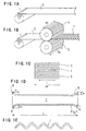
- Corrugated plate 1 used for this type of a catalyst carrier 3 is normally formed by passing plain sheet 2 between a pair of threaded gears 5, shown in Figs. 1B and 1C.
- Width L of carrier 3 and, therefore, width L of corrugated sheet 1 varies according to needs and so width M of toothed gears 5 is set wider than width L to cope with sheets having various width L. That is, plain sheet 2 having width L, which is narrower than width M of a pair of toothed gears, has been processed to form corrugated sheet 1.
- the formed corrugated sheet has inevitably a shape shown in Fig. 1 D, wherein triangular projections 6 are formed at right and left side ends at the top ad the bottom of the sheets.
- Projections 6 have width N of about 5 mm and height H of about 15 ⁇ m.
- the obtained carrier of the first prior art example has a shape illustrated in Figs. 10A to 10C.
- the rolled sheets 1 and 2 are diffusion bonded at projecting ends 7 of the projections of sheet 1 in a point contact manner. That is, they are bonded only at small points.
- Gears 8 had a special form wherein the side ends of the tooth of toothed gear 5 are rounded to form a corrugated sheet 9 having no projections 6 at side ends, contrary to gears 5 of the invention where the side ends are not rounded as shown in Figs. 1B and 1C.
- corrugated plate 9 is bonded linearly to plain sheet 2 and, therefore, the bonding strength between sheets is higher than that of the carrier of the first prior art example.
- gears 8 of the second example have not practically been used for the reason of the costs. This is because special form toothed gears 8 should be prepared for each of different sized corrugated sheets 1 and carriers 3.
- a third prior art example is to apply a strong tension from backside to plain sheet 2 when corrugated sheet 1 and plain sheet 2 are wound to from a roll.
- the sheets are inserted into cylinder 10 (Fig. 3A) while the sheets are strongly tensioned, to form catalyst carrier 3.
- the tension force By applying the tension force, the bonding strength between sheets is increased and whereby the carrier has an enough strength.
- this example does not solve the problem relating to projections 6 of corrugated sheet 1, as pointed out for prior art example 1.
- the fourth solution for increasing the contact area between sheets and, thereby increasing the bonding strength includes pressing only the side ends of corrugated sheet 1 to forcibly remove projections 6, using a special form corrugated sheet 1 having no rounded ends, and/or removing the surface roughness of the sheets.
- the fifth solution is to form a throttled portion in cylinder 10 after a sheet roll was inserted therein, mechanically or by the use of the thermal expansion difference from jig or other tool used, for increasing the contact strength between sheets locally and for increasing the bonding strength.
- the solution also is defective in the point of the cost, as an additional work is necessary for forming the throttled portion.
- Figs. 10F and 10G The sixth prior art example shown in Figs. 10F and 10G is discussed in Japanese Unexamined Patent Publication (Kokai) 7-39765.
- belt-like second plain sheet 11 is inserted between sheets 1 and 2 at side ends, for increasing the contact strength between sheets locally and for increasing the bonding strength.
- an area between plain sheet 2 and second plain sheet 11 is diffusion bonded.
- the portion between corrugated sheet 1 and second plain sheet 11 is bonded in a spot-like manner as has been pointed out with reference to prior art example 1. That is, sheets 1 and 11 are only point-bonded to each other at ends (points) of projections 6 and, therefore, the bonding strength is insufficient.
- the seventh prior art example shown in Figs. 10H and 10I is discussed in Japanese Unexamined Patent Publication (Kokai) 8-281123. It shows inserting belt-like thin film 12 between sheets 1 and 2 while they are wound to a roll, at the portion remote from side ends of the sheets, to form a swelled portion 13 around the roll. The roll is then inserted into cylinder 10 whose inner diameter corresponds to an outer diameter of the portion of the roll not swelled. Since the roll having swelled portion 13 is forcibly inserted into cylinder 10, the swelled portion is throttled whereby the contact pressure between sheets is increased and the bonding strength between the sheets is increased.
- the forcibly inserting step requires a strong pressing force, resulting in increasing the cost for carrying out the step and for the tool required therefor.
- the corrugated form may be collapsed by the force applied.
- a novel catalyst carrier for an exhaust gas purification system and a method for producing the catalyst carrier are provided to overcome the above mentioned problems.
- the carrier is made by winding thin belt-like bonding assistants between belt-like corrugated sheet and plain sheet when the sheets are wound, wherein each of the assistants is positioned radially inside from the projections formed at side ends of the corrugated sheet.
- the assistants has a thickness greater than the height of the projections and a predetermined width, and is used in pairs via the plain sheet.
- the catalyst carrier of the invention has a full bonding strength in spite that the sheets are diffusion bonded, has increased resistance to trembling and heat and increased thermal stress easing properties. It is produced by a simplified process at a low cost.
- a catalyst carrier for an exhaust gas purification system comprising bands of stainless steel-made at least one corrugated sheet and at least one plain sheet which hold stainless steel-made bonding assistants therebetween, wherein said bonding assistants have a width narrower than those of said sheets, wherein said sheets are alternated and are wound to form a roll having a honeycomb structure comprising a number of cell spaces, wherein catalyst materials are adhered to sheets, wherein said sheets are diffusion bonded to each other via bonding assistants, wherein said bonding assistants are positioned at locations radially inside the projections formed at side ends of the corrugated sheet during passing the corrugated sheet through a pair of toothed gears, and wherein said bonding assistants have a thickness greater than the height of the projections.
- a catalyst carrier of claim 1 comprising one corrugated sheet and one plain sheet, each being made of stainless steel containing aluminum, wherein both sheets have substantially same length and width, and the length of assistants is substantially same as that of the both sheets.
- a catalyst carrier of claim 1 wherein the assistants are positioned at locations 5mm or more inside the side ends of said sheets, and have a thickness of from 20 to 200 ⁇ m.
- a catalyst carrier of claim 3 wherein the assistants are used in a pair or pairs via a plain sheet, and wherein the width of an assistant is 0.5 to 5 mm, and the ratio of the total width of all assistants to the width of the sheets is 0.3 to 20%.
- each in paired assistants faces to the other via plain sheet to increase the contact pressure between the corrugated- and plain-sheets.
- each in paired assistants is shifted to the other via the plain sheet to increase thermal stress easing properties.
- the catalyst carrier comprises a roll of a corrugated sheet and a plain sheet with bonding assistants therebetween, and has a honeycomb structure of a number of cell rooms.
- the corrugated sheet and the plain sheet are of a belt-type, and are made of stainless steel containing aluminum.
- the corrugated sheet has projections having about 5mm width and about 15 ⁇ m height.
- the bonding assistant is a narrow wide belt, made of stainless steel, and is positioned inside from the location of the projections formed at side ends of the corrugated sheet, and has a thickness greater than the height of the projections.
- each of the assistants is positioned 5mm or more inside the positions of the side ends of the sheets, and has a thickness of 20 to 200 ⁇ m.
- the assistants are used in a pair or pairs via a plain sheet, and wherein the assistant has 0.5 to 5 mm width, and the ratio of the total width of all assistants to the width of the sheets is 0.3 to 20%. Further, each in paired assistants faces to the other or is shifted to the other via the plain sheet.
- the corrugated- and plain-sheets are wound with bonding assistants therebetween, they are free from the influence of the projections of the corrugated sheet.
- the sheets are diffusion bonded radially at short lines with locally centered high contact pressure.
- the produced catalyst carrier is, thus, improved in strength with regard to the resistance to trembling and heat, in thermal stress easing properties. With the use of bonding assistants, the catalyst carrier is produced easily at low cost.
- Catalyst carrier 14 of the invention is produced by the steps of 1. preparing sheets 1 and 2, 2. preparing bonding assistants 15, 3. winding, 4. diffusion bonding and 5. production of catalyst carrier 14. The invention is explained with each of the steps above.
- Corrugated sheet 1 and plain sheet 2 of catalyst carrier 14 are made from a thin foil stainless steel sheet having a 200 ⁇ m, 100 ⁇ m or 50 ⁇ m thickness.
- a ferrite stainless steel containing aluminum, such as Fe-20Cr-5AI alloy and Fe-18Cr-3AI alloy are typically used because the sheets are used in a high temperature atmosphere and at a portion where heated and cooled conditions are repeated.
- corrugated sheet 1 and plain sheet 2 i.e., the surface of ferrite stainless steel
- a protective oxidized film of Cr 2 O 3 but the film is reduced at a temperature range at 800° C or higher, whereby it loses its protecting properties to oxidation. Therefore, the film on the surfaces of the sheets contains Al 2 O 3 (alumina) in addition to Cr 2 O 3 .
- Al 2 O 3 is not reduced even at a high temperature of 1,200 ° C or higher whereby it prevents sheet 1 or 2 from being oxidized, see Fig. 5D.
- Plain sheet 2 is produced by unrolling a roll to a plain belt of a 10 mm to 150 mm width, and by cutting the belt to a suitable length, as shown in Fig. 1A.
- Corrugated sheet 1 is produced by passing plain sheet 2 obtained by unrolling a roll between a pair of toothed gears 5 under heat and pressure, as shown in Figs. 1B, 1C, 1D and 1E.
- Produced corrugated sheet 1 has repeated waves having a predetermined height running widthwise, with a width L of 10mm to 150 mm, and is cut to a certain length. Width L and the length of corrugated sheet 1 are same as those of plain sheet 2.
- the cross section of the wave is typically a triangle having a dull edge.
- Width M of toothed gears 5 is wider than width L of sheet 1 or 2, so that a single pair of rollers can process corrugated sheets 1 of various widths L. That is, a pair of gears 5 having about 200 mm width can process plain sheets 2 of a width of 150mm, 100mm, 75mm, 50mm, etc.
- corrugated sheet 1 processed by toothed gears 5 has, inevitably, a form shown by a sectional plan view shown in Fig. 1D. That is, corrugated sheet 1 has a pitch at right and left ends narrower than that at the center portion, and projections 6 projected from the right and left ends are formed thereby.
- the projection has a shape of gently sloping triangular half.
- Projection 6 has width N of about 5mm starting from the beginning of the slope, and height H of about 15 ⁇ m. In other words, projection 6 starts from about 5mm (width N) inside the right and left ends, and projects about 15 ⁇ m (height H) from the center portion.
- Bonding assistant 15 is used in winding step 3, mentioned later, and functions as a bonding portion at a diffusion-bonding step mentioned later.
- the assistant can be made of various types of stainless steel. When it is made of normal ferrite such as SUS 430 and SUS 409, a higher diffusion speed is obtained whereby the diffusion bonding step 4 proceeds swiftly. On the other hand, when it is made of normal austenite type stainless steel such as SUS 304 and SUS 309 having a greater thermal expansion coefficient, the contact pressure between the corrugated sheet 1 and the plain sheet 2 is increased. Thus, the assistant which is excellent in bonding strength is obtained.
- bonding assistant 15 is made of a material same as that of the sheets, that is, when the assistant is made of ferrite type stainless steel, Fe-Cr-AI alloy, it shows most strong oxidation resistant properties.
- Assistant 15 is a thin belt having a thickness T of from 20 to 200 ⁇ m, generally 30 to 50 ⁇ m.
- assistant 15 has thickness T of 20 ⁇ m or more which is thicker than around 15 ⁇ m height H of diffusion projection 6 formed at side ends of corrugated sheet 1 as mentioned earlier.
- Assistant 15 is used as a bonding portion between sheets 1 and 2.
- Thickness T is maximum 200 ⁇ m since if T is too great, gap U between sheets 1 and 2 is broadened, resulting in the reduction in the bonding strength. Further details will be discussed in Example 1.
- Narrow belt-shape bonding assistant 15 of such thickness T and width W has a length substantially similar to those of sheet 1 or 2.
- Figs. 2, 5 and 6 are referred to.
- stainless steel sheets 1 and 2 with assistants 15 therebetween are wound to form a roll.
- corrugated sheet 1 As will be clear from Figs. 2A to 2C, corrugated sheet 1, one or more plain sheets 2 of a length same as that of sheet 1, and one or more thin diffusion assistants 15 are superimposed with each other. Then they are wound to form a round roll of multiple layers.
- Fig. 2A shows a single plain sheet structure, which is most often used, comprising single corrugated sheet 1 and single plain sheet 1.
- Fig. 2B shows a semi-double plain sheet structure wherein single corrugated sheet 1 and two plain sheets 2 are used at the outer portion of the roll while one sheet 1 and one plain sheet 2 are used at the inner portion. That is, one plain sheet is used to partway and then two plain sheets 2 are used.
- Fig. 2C shows a double plain sheet structure wherein one corrugated sheet 1 and two plain sheets 2 at all windings. In Figs. 2B and 2C, a two plain sheets winding is shown by a thick line while one plain sheet winding is shown by a thin line.
- Catalyst carrier 14 of the semi-double or double structure is used in the case where the carrier is strongly trembled and thermally stressed and, therefore, high tremble resistant properties and high thermal stress easing properties are required.
- the semi-double or double structure no local contacting pressure is produced between two plain sheets 2 and the sheets are not diffusion bonded to each other, though a contacting pressure between corrugated sheet 1 and plain sheets 2 are maintained. Therefore, since the plain sheets slide on each other, the structure is improved in the tremble-resistant and thermal stress easing properties.
- Bonding assistant 15 normally is not put between plain sheets for these structures. In some case, even a bonding preventive agent is coated to plain sheets. However, when catalyst carrier 14 is weak in maintaining its shape such as when axial width L of sheet 1 or 2 are short, a minimum number of bonding assistants may be put between sheets 2 to improve the shape-maintaining properties.
- the assistant is axially arranged at the position radially inside projection 6.
- projections 6 are formed about 5mm (width N) inside the ends of sheet 1.
- assistants 15 are positioned more than 5 mm inside the ends.
- Bonding assistants 15 are used in pair or pairs via plain sheet or sheets 2, as shown in Figs. 2A-2C, 5A and 6.
- the total width of the assistant or assistants is 0.3 to 20% of width L of sheet 1 or 2.
- Assistant 15 has 0.5 to 5 mm width W as discussed previously and a single or a plurality number of assistants may be used in pair or pairs.
- the total of width W of assistants15 is regulated by width L of sheet 1 or 2.
- minimum width W is 0.5 mm and the minimum number of the assistant is one.
- Maximum width L of sheet 1 or 2 for catalyst carrier 14 is normally 150 mm. Therefore, the minimum ratio of the assistant to width L is calculated by a formula (0.5/150) x 100, i.e., 0.3 %. The ratio of the total should be 20% or less. If the ratio is over 20%, the contacting pressure between sheets 1 and 2 becomes insufficient for a required contacting strength between sheets. This matter will be discussed in Example 3.
- Figs. 6A through 6F show paired assistants face to each other via sheet 2, whereby the pressure between corrugated sheet 1 and plain sheet 2 is strengthened.
- catalyst carrier 14 of this type is suitably used for a two-wheeled vehicle such as a motor scooter whose carrier is strongly trembled and has weak thermal stress.
- paired assistants 15 shown in Figs. 6G through 6J do not face to each other, but are shifted to each other via plain sheet 2, whereby the thermal stress easing properties between sheets 1 and 2 are improved.
- Catalyst carrier 14 of this type is used suitably for a four-wheeled vehicle whose carrier is not strongly trembled and receives repeating thermal stress.
- the catalyst carrier When the catalyst carrier is strongly trembled and receives high thermal stress, there may be used the facing pairs or shifting pairs of assistants 15 in combination with previously mentioned semi-double or double structure of plain sheets 2.
- Catalyst carrier 14 used for a strongly trembled vehicle should have bonding surface area as large as possible.
- the bonding assistant should have greater width W while the number of the assistants used is reduced.
- carrier 14 used for a vehicle, whose carrier receives strong thermal stress should receive less stress at each bonding portion to improve the stress easing properties. Therefore, assistants 15 having narrower width W are used and the number of the assistants used are increased.
- Figs. 3A to 3C are referred to.
- sheets 1 and 2 which were wound to a roll with one or more bonding assistants at winding step 3 mentioned above, are bonded to each other at bonding positions.
- Rolled sheets 1 and 2 receive pressure only for maintaining the wound shape. That is, they receive only weak force to maintain the wound form and do not receive strong force to change the shape of corrugated sheet 1.
- a roll of sheets 1 and 2 with assistants 15 are inserted into cylinder 10 shown in Fig. 3A.
- the sheets are smoothly inserted without receiving any particular pressure between cylinder 10 and the roll.
- Cylinder 10 of stainless steel for example has slit 17, which may be welded before or after the insertion of the sheets.
- a seamless pipe may be used as cylinder 10.
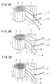
- the roll of sheets 1 and 2 with assistants 15, inserted into cylinder 10, is transferred into vacuum furnace 19 having heaters 18 as shown in Fig. 3B and are subjected to a diffusion bonding step.
- the diffusion bonding is carried out in reduced-pressure or deoxidation atmosphere such as in a vacuum, in an argon or inert gas atmosphere, at a temperature between 1,150 to 1,300° C.
- the process is carried out for 30 minutes to 3 hours.
- corrugated sheet 1 is expanded to the direction vertical to the axial direction whereby a locally high contacting pressure is exerted between bonding assistants 15 and sheet 1 and between the assistants and sheet 2, Thus, a high pressure necessary for the diffusion bonding is obtained.
- the diffusion bonding is effected between corrugated sheet 1 at the top and bottom portions and the corresponding portions of bonding assistant 15, and between plain sheet 1 and all surfaces of the assistants (Figs. 5A, 5B and 5C). Consequently, sheets 1 and 2 are diffusion bonded to each other at contacting portions of short lined areas via the assistants.
- metallic atoms forming the stainless steel move between surfaces of corrugated sheets 1, plain sheets 2 and assistants 15, whereby the contacting portions of sheets 1 and 2 are diffusion bonded in solid phase via the bonding assistants.
- brazing agent 20 may be used as shown in Fig. 6A, since the temperature at the portion near cylinder 10 is relatively low in comparison to that at the core portion of carrier 14.
- Catalyst carrier 14, shown in Figs. 3C and 5A through 5C, for use in exhaust gas cleaning system 16 is produced by the steps of 1) preparing sheets 1 and 2, 2) preparing bonding assistants 15, 3) winding and 4) diffusion bonding.
- the carrier comprises a roll of sheets 1 and 2 with bonding assistants therebetween, and has a honey comb structure comprising a number of cellular spaces 4.
- the carrier has a roll shape and a honeycomb structure and is inserted in cylinder 10.
- a typical roll has a shape of a circular cross-section as shown in Fig. 3A, but the roll may have a form of an elliptical or angular cross-section.
- the honeycomb structure comprises a number of hollow columns of cellular spaces, defined by cell walls of corrugated sheets 1 and plain sheets 2, with open column ends.
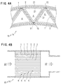
- Cell walls and cell spaces 4 have substantially triangular shapes with dull edges in cross-section as shown in Fig. 4A, but they may have trapezoidal or other shapes.
- the honeycomb structure is excellent in the strength to weight, is light-weighted, and has high rigidity and strength. Further, it has good rectifying effect, has a great surface area per unit volume, and other excellent features.
- catalyst carrier 14 uses the effect of the great surface area per unit volume.
- Catalyst material 21 is adhered to the surfaces of sheets 1 and 2 and the bonding assistants 15 which constitute cell walls 4 as shown in Fig. 4A.
- Fig. 4B shows that a greater area for the contact between passing exhaust gas 22 and catalyst material 21 is obtained and that the harmful substance contained in exhaust gas 22 is reacted with catalyst material 21 and is removed, and thereby the exhaust gas is purified.
- Catalyst carrier 14 is used under the condition where high temperature exhaust gas 22 passes and where heat is generated by the catalytic reaction. It is used in exhaust gas purifying system 16 for two wheeled cars such as auto-bikes and motor scooters, four wheeled cars, chain saws, and other internal combustion engines.
- Catalyst material 21 is selected from materials such as noble metals which react with harmful substance such as carbon monoxide, nitrogen oxide and hydrocarbon, and is coated on the alumina-containing surface of sheets 1 and 2.
- Belt-like sheets 1 and 2 of the catalyst carrier are made of stainless steel containing aluminum, and have substantially same length and width L.
- Corrugated sheet 1 has diffusion projections 6 at both side ends of the top and bottom portions, which are formed when sheet 1 passes through a pair of toothed gears 5.
- Projection 6 has a substantially triangular pyramid having width N of about 5mm and height H of about 15 ⁇ m, see Fig. 1D.
- Bonding assistant15 used for carrier 14 is made of stainless steel and has a length similar to those of sheets 1 and 2 but have a thinner width, see Figs. 2A to 2C.
- Assistants 15 are located radially inside the positions of projections 6 formed at the left and right hand ends of the sheet 1 and have thickness T greater than height H of projections 6, see Fig. 5A. They are located 5mm or more inside the side ends of sheets 1 and 2, and have thickness T of 20 to 200 ⁇ m.
- the assistants are used in pairs via plain sheet 2, one or a plural numbers in each side of sheet 2, with width W of 0.5 to 5mm and the total width of the assistants being 0.3 to 20% of width L of sheet 1 or 2.
- the pairs of the bonding assistants facing to each other via plain sheet 2 increase the contacting pressure between plates 1 and 2, while the pairs may be shifted to each other to increase the thermal stress easing capability, see Fig. 6.
- catalyst carrier 14 are produced by the steps of 1) preparing sheets 1 and 2, 2) preparing bonding assistants 15, 3) winding and 4) diffusion bonding. Sheets 1 and 2 are wound with assistants 15 therebetween, and produced carrier 14 has the features below.
- sheets 1 and 2 are diffusion bonded to each other via bonding assistants 15 with locally strong contacting pressure, without the influence of projections 6 formed at side ends of sheet 1. That is, the top and the bottom of sheet 1 are diffusion bonded under high contacting pressure to plain sheet 1 by using bonding assistants 15, not by contact at points, but by contact at short lined areas.
- the assistants are located at predetermined positions and have predetermined thickness T and width W. Therefore, they are not influenced by projections 6 when pressed, receive high pressure when corrugated sheet 1 is expanded under heat, and receive locally centered pressure at short lined areas, see Figs. 5A and 5C.
- catalyst carrier 14 whose sheets 1 and 2 are diffusion bonded firmly to each other, is improved in trembling-resistant, heat resistant thermal stress easing properties and is strong.
- the excellent properties are easily realized by only holding bonding assistants 15 with predetermined thickness T and width W at predetermined positions and carrier 14 is easily produced as discussed below.
- conventional toothed gears 5 are used to produce corrugated sheets 6 having diffusion projections 6 at side ends, see Fig.1, and no special toothed gears 8 as shown in Fig. 10D is needed and there is no need to remove projections 6 from corrugated sheets 8, as shown in Fig. 10E.
- the roll of sheets 1 and 2 with assistants is inserted into cylinder 10 without being strongly pressed, as shown in Fig. 3.
- Corrugated sheet 1 having an approximately triangular shape with dull ends (tops) are used for the invention. Therefore no special procedure is necessary, such as pressing sheet 1 to remove the projections or using a sheet having no dull ends. Further, no procedure to remove surface roughness of sheet 1 is needed since a high contact pressure for strong bonding is obtained by the use of assistants 15.
- Sheets 1 and 2 rolled with pressure of only maintaining its shape is simply inserted into cylinder 10, as discussed above. Since corrugated sheet 1 expands by heat, high contact pressure is applied locally to positions where the sheet contacts the bonding assistants and the diffusion bonding proceeds with a sufficient bonding strength. There is no need to provide a further process to obtain sufficient contact pressure for the diffusion bonding.
- the bonding step itself is simple. As discussed above, a contact pressure necessary for the diffusion bonding is obtained locally by the use of bonding assistants 15, and no strict control on the atmosphere, temperature and time is needed.
- a protective oxidized layer, Al 2 O 3 is formed on the surface of sheets 1 and 2, as shown in Fig. 5D.
- the layer is broken due to the difference in thermal expansion coefficient between the sheets and the layer.
- aluminum in the sheets diffuses outside, reacts with oxygen in air and forms new oxidized layer Al 2 O 3 .
- the surface of the sheets is always covered with protective oxidized layer to assure the oxidation resistant properties.
- the protective oxidized layer Al 2 O 3 is quite thin (5 ⁇ m or less) and is broken under heat. Therefore, the layers of sheets 1 and 2 are exposed and directly contacted with each other if high pressure is applied as is the case with the present invention, and they are diffusion bonded. Contrary to this, if high pressure cannot be applied to surfaces, it is necessary to strictly control the processing conditions such as atmosphere, temperature and time while evaporating aluminum.
- a high contacting pressure is locally obtained to bond the sheets by using bonding assistants 15, the processing conditions need not be strictly controlled. That is, the diffusion bonding process can be carried out in wide range of low pressure or reduction conditions, at relatively low temperature and in relatively short time. Thus, the diffusion bonding process can be simplified according to the invention.
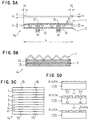
- the strength of catalyst carrier 14 as shown in Fig 3C was tested using bonding assistants of various thickness T and width W as illustrated in Fig. 5A.
- the strength herein means the resistance to passing through the carrier or shearing strength between sheets 1 and 2, i.e., bonding strength.
- Data common to Examples 1 through 5 are as follows:
- the strength test was carried out as follows.
- Catalyst carrier 14 comprising a sheet roll in cylinder 10 was placed lengthwise on short cylindrical holder 23, see Fig. 7A.
- the holder has a diameter and a thickness same as those of cylinder 10 and supports the cylinder but do not carry an inner roll.
- Penetrator 24 having a short cylindrical shape and a diameter smaller than that of carrier 14 was placed on the open top of the catalyst carrier, and was pressed at various load from above.
- Fig. 7B shows the test results of the carrier strength when thickness T of bonding assistants 15 is varied. Supplemental data is as follows:
- catalyst carrier 14 has a diameter of 60mm and width L of 60 mm, i.e. corrugated sheet 1 and of plain sheet 2 have width L of 60 mm.
- Bonding assistants held between sheets have width W of 5 mm and are used such that two pairs of two assistants each face to each other via plain sheet 2.
- Fig. 7B shows that the penetrating strength or sheering strength mentioned earlier was reduced when thickness T of bonding assistant 15 is 15 ⁇ m, since it is equal to height H, i.e., 15 ⁇ m, of triangular projection 6 formed at side ends of corrugated sheet 1. That is, the bonding or contacting pressure between sheets was reduced because it was dispersed to two short lined areas of contact of two assistants with plain sheet 2, and to two points at tops of projection 6.
- Example 1 When thickness T is over 200 ⁇ m, the strength is lowered again, since gap U between assistants 15 corresponding to thickness T (see Figs. 6A and 6B) becomes too great to maintain sheets 1 and 2 in planar state.
- the results obtained in Example 1 show that the thickness T of bonding assistant 15 should be from 20 to 200 ⁇ m.
- width L i.e., the axial length of catalyst carrier 14 which corresponds to radial width L of sheets 1 and 2
- strength was measured.
- the total width of assistants i.e., the total of each width W of all the assistants including one assistant held between sheets
- width L of carrier 14 which corresponds to width L of sheets 1 and 2.
- the pressure should be locally centered to the portion of the contact of assistants with sheets. If ratio of sheet width L to the total width of assistants is less than a certain limit, the centered pressure becomes insufficient. Thus, it was revealed that the total width of assistants 15 is regulated by width L of sheets 1 and 2.
- Example 3 was obtained based on the results of Example 2.
- Fig. 8B shows the results of the total of each width W of all bonding assistants to width L of carrier 14 corresponding to sheet width L, to load.
- the data conditions of Example 3 are same as that of Example 2.
- width W of assistants is regulated by width L of sheets 1 and 2 (width L of carrier 14). If not, the pressure is not centered, resulting in insufficient bonding strength between sheets.
- Fig. 8B shows that the strength is reduced when the total width of each width W of assistants 15 is over 20% of width L of sheets and it was revealed that the total width should be less than 20% of width L of sheets.
- Width W of bonding assistants 15 was varied and the strength of carrier 14 was measured to produce Fig. 9A. Supplemental data is as follows:
- width W of bonding assistant W should be 5mm or less.
- the minimum width is 0.5mm and the value of the total width should be 20% or less to that of carrier width L, as discussed in Example 3.
- Example 5 the number of bonding assistants was varied to produce the results shown in Fig. 9B. Supplemental data is as follows:
- catalyst carrier 14 has a diameter of 60mm and width L (sheet width L) of 150 mm.
- Bonding assistants 15 held between sheets 1 and 2 have thickness T of 100 ⁇ m and a pair or pairs of assistants face to each other via plain sheet 2.
- the number (row) of the assistants used was changed while the total width of assistants was arranged same to all carriers and the strength of carrier 14 was measured.
- the catalyst carrier for an exhaust gas clearing system of the invention is produced by holding thin-belt like bonding assistant or assistants between broader-belt like corrugated sheet and plain sheet, wherein the assistants are positioned radially inside the projections formed at ends of the corrugated sheet, with a thickness greater than the height of projections and with a predetermined width.
- the catalyst carrier is excellent in the strength with regard to trembling resistant and heat-resistant properties and thermal stress easing properties.
- sheets 1 and 2 are diffusion bonded by locally centered high pressure by using bonding assistants, in spite of projections formed on corrugated sheets. That is, sheets are bonded not at points, as is the case with conventional process, but at short line areas, The sheets are strongly bonded and have the strength necessary for making a strong catalyst carrier. Therefore, the carrier is improved in trembling resistant properties, for example, and it endures long run fatigue and exhaust gas pressure, and is most suitable for the use in two and four wheeled cars.
- the catalyst career 14 is composed of sheets 1 and 2 of stainless steel containing aluminum and of bonding assistants 15 of stainless steel and an oxidized protective layer is surely produced on the surfaces of the sheets as shown in 5D. Therefore, the carrier has excellent oxidation resistant properties and is improved in heat resistant properties and heat resistant strength. Thus, also from this point, the carrier is most suitable for high temperature gas exhaust devices, and for two and four wheeled cars.
- the sheets are not diffusion bonded at all surfaces, but only at the linear portion of the contact of the bonding assistants with sheets and, therefore, thermal stress easing properties between bonded sheets are improved. Particularly, the properties are improved when each of the pair of bonding assistants is shifted to other via a plain sheet.
- the advantageous effect mentioned above can be realized in a simple manner, since the catalyst carrier can be produced by holding bonding assistants of a predetermined thickness and a width, at predetermined positions between sheets.
- the advantageous cost performance can be discussed as follows:
Abstract
Description
- The present invention relates to a catalyst carrier for an exhaust gas purification system and a method for producing the catalyst carrier. More particularly, it relates to the catalyst carrier having a honeycomb structure formed by winding stainless steel-made corrugated sheet and plain sheet, and said sheets are covered with a catalyst material.
- Two-wheeled cars such as motor bikes and scooters and four-wheeled cars are provided each with an exhaust gas purification device for discharging exhaust gas containing harmful substances from engines. The conventional exhaust gas purification device has a
catalyst carrier 3, as shown in Fig. 3C, of a honeycomb structure comprising, typically, acorrugated sheet 1 and aplain sheet 2 which are wound to a roll and which are provided with a catalytic material layer. By passing the exhaust gas throughcell spaces 4 formed incatalyst carrier 3, harmful substances contained in the gas react with the catalytic material and are purified. The device and, accordingly,catalyst carrier 3 is used in severe conditions of high temperature or repetition of heating and cooling, and in a trembling condition. - For
conventional catalyst carrier 3,sheets bond sheets - The temperature of
catalyst carrier 3 rises to 700° C or higher due to a catalytic reaction during running of the car, and even higher than 1,000° C recently when a high performance catalyst is used. Unburned raw gas is sometimes discharged from engines. A large amount of unburned gas is discharged particularly by two-wheeled cars. Such unburned gas is often ignited when it reachescatalyst carrier 3 and burns to raise the carrier temperature to over 1,200° C. To cope with this situation, aluminum contained instainless steel sheets - It has been pointed out that the oxidation-resistant and heat-resistant properties of
sheets - According to the prior art, nickel, a main component of the brazing agent, disperses to
corrugated sheet 1 orplain sheet 2 and reacts with aluminum to deposit Ni3Al, an intermetallic compound, resulting in reducing aluminum insheets sheets sheets catalyst carrier 3 is reduced, causing abnormal oxidation, particularly at the portions wheresheets - In addition, boron and silicon, added to the brazing agent as melting point depressants to make easier the brazing work, move to the sheets and depress the melting point by heat. Consequently, when the carrier sheets are heated to above 1,200° C, brazed portions are melted again and portions surrounding the brazed portions in the sheets are melted or pores are formed.
- A technology has been developed recently to diffusion bond a corrugated sheet to a plain sheet of a catalyst carrier, without using the brazing agent. According to this method, the sheets are directly bonded to each other and, no abnormal oxidation or re-melting phenomenon occurs since no brazing agent is used. Thus, the basic properties of stainless steel sheets are well maintained and the sheets are strong in thermal resistance. Since an expensive brazing agent is not used, the method is superior to the prior art technology.
- However, problems have been pointed out for the catalyst carrier produced by the diffusion bonding process. In explaining the problems, reference is made to Figs. 10A to 10I, which illustrate the conventional technology using the diffusion bonding process.
-
Corrugated plate 1 used for this type of acatalyst carrier 3 is normally formed by passingplain sheet 2 between a pair of threadedgears 5, shown in Figs. 1B and 1C. - Width L of
carrier 3 and, therefore, width L ofcorrugated sheet 1 varies according to needs and so width M oftoothed gears 5 is set wider than width L to cope with sheets having various width L. That is,plain sheet 2 having width L, which is narrower than width M of a pair of toothed gears, has been processed to formcorrugated sheet 1. The formed corrugated sheet has inevitably a shape shown in Fig. 1 D, whereintriangular projections 6 are formed at right and left side ends at the top ad the bottom of the sheets. -
Projections 6 have width N of about 5 mm and height H of about 15µm. Whencorrugated sheet 1 havingprojections 6 andplain sheet 2 are wound to a roll as shown in Fig. 3C and are diffusion bonded, the obtained carrier of the first prior art example has a shape illustrated in Figs. 10A to 10C. As will be clear from these figures, the rolledsheets ends 7 of the projections ofsheet 1 in a point contact manner. That is, they are bonded only at small points. - It has been pointed out that the bonding strength between sheets is insufficient since the sheets are only spot bonded to each other.
- In order to overcome the drawbacks above, it has been proposed to use a pair of
toothed gears 8 shown in Figs. 10D and 10E, of a second prior art example.Gears 8 had a special form wherein the side ends of the tooth oftoothed gear 5 are rounded to form acorrugated sheet 9 having noprojections 6 at side ends, contrary togears 5 of the invention where the side ends are not rounded as shown in Figs. 1B and 1C. In the catalyst carrier of the second prior art example,corrugated plate 9 is bonded linearly toplain sheet 2 and, therefore, the bonding strength between sheets is higher than that of the carrier of the first prior art example. - However,
gears 8 of the second example have not practically been used for the reason of the costs. This is because specialform toothed gears 8 should be prepared for each of different sizedcorrugated sheets 1 andcarriers 3. - A third prior art example, not shown, is to apply a strong tension from backside to
plain sheet 2 whencorrugated sheet 1 andplain sheet 2 are wound to from a roll. According to the example, the sheets are inserted into cylinder 10 (Fig. 3A) while the sheets are strongly tensioned, to formcatalyst carrier 3. By applying the tension force, the bonding strength between sheets is increased and whereby the carrier has an enough strength. But it is difficult to insert the sheet roll intocylinder 10 while the sheets are tensioned, and it needs high skill and experience. Further, this example does not solve the problem relating toprojections 6 ofcorrugated sheet 1, as pointed out for prior art example 1. - The fourth solution for increasing the contact area between sheets and, thereby increasing the bonding strength includes pressing only the side ends of
corrugated sheet 1 to forcibly removeprojections 6, using a special formcorrugated sheet 1 having no rounded ends, and/or removing the surface roughness of the sheets. - The solution, however, requires costs for the steps of pressing the side ends, preparing
special form sheet 1 and for removing the roughness. Further, even if these steps are carried out, the problem relating toprojections 6 is not solved. - The fifth solution, not shown, is to form a throttled portion in
cylinder 10 after a sheet roll was inserted therein, mechanically or by the use of the thermal expansion difference from jig or other tool used, for increasing the contact strength between sheets locally and for increasing the bonding strength. The solution also is defective in the point of the cost, as an additional work is necessary for forming the throttled portion. - The sixth prior art example shown in Figs. 10F and 10G is discussed in Japanese Unexamined Patent Publication (Kokai) 7-39765. In the example, belt-like second
plain sheet 11 is inserted betweensheets - According to the sixth example, an area between
plain sheet 2 and secondplain sheet 11 is diffusion bonded. But the portion betweencorrugated sheet 1 and secondplain sheet 11 is bonded in a spot-like manner as has been pointed out with reference to prior art example 1. That is,sheets projections 6 and, therefore, the bonding strength is insufficient. - The seventh prior art example shown in Figs. 10H and 10I is discussed in Japanese Unexamined Patent Publication (Kokai) 8-281123. It shows inserting belt-like
thin film 12 betweensheets portion 13 around the roll. The roll is then inserted intocylinder 10 whose inner diameter corresponds to an outer diameter of the portion of the roll not swelled. Since the roll having swelledportion 13 is forcibly inserted intocylinder 10, the swelled portion is throttled whereby the contact pressure between sheets is increased and the bonding strength between the sheets is increased. - However, the forcibly inserting step requires a strong pressing force, resulting in increasing the cost for carrying out the step and for the tool required therefor. Further, the corrugated form may be collapsed by the force applied.
- According to the invention, a novel catalyst carrier for an exhaust gas purification system and a method for producing the catalyst carrier are provided to overcome the above mentioned problems. The carrier is made by winding thin belt-like bonding assistants between belt-like corrugated sheet and plain sheet when the sheets are wound, wherein each of the assistants is positioned radially inside from the projections formed at side ends of the corrugated sheet. The assistants has a thickness greater than the height of the projections and a predetermined width, and is used in pairs via the plain sheet.
- The catalyst carrier of the invention has a full bonding strength in spite that the sheets are diffusion bonded, has increased resistance to trembling and heat and increased thermal stress easing properties. It is produced by a simplified process at a low cost.
- According to the invention, there is provided a catalyst carrier for an exhaust gas purification system, comprising bands of stainless steel-made at least one corrugated sheet and at least one plain sheet which hold stainless steel-made bonding assistants therebetween, wherein said bonding assistants have a width narrower than those of said sheets, wherein said sheets are alternated and are wound to form a roll having a honeycomb structure comprising a number of cell spaces, wherein catalyst materials are adhered to sheets, wherein said sheets are diffusion bonded to each other via bonding assistants, wherein said bonding assistants are positioned at locations radially inside the projections formed at side ends of the corrugated sheet during passing the corrugated sheet through a pair of toothed gears, and wherein said bonding assistants have a thickness greater than the height of the projections.
- According to
claim 2, there is provided a catalyst carrier ofclaim 1, comprising one corrugated sheet and one plain sheet, each being made of stainless steel containing aluminum, wherein both sheets have substantially same length and width, and the length of assistants is substantially same as that of the both sheets. - According to
claim 3, there is provided a catalyst carrier ofclaim 1, wherein the assistants are positioned at locations 5mm or more inside the side ends of said sheets, and have a thickness of from 20 to 200µm. - According to
claim 4, there is provided a catalyst carrier ofclaim 3, wherein the assistants are used in a pair or pairs via a plain sheet, and wherein the width of an assistant is 0.5 to 5 mm, and the ratio of the total width of all assistants to the width of the sheets is 0.3 to 20%. - According to
claim 5, there is provided a catalyst carrier ofclaim 4, wherein each in paired assistants faces to the other via plain sheet to increase the contact pressure between the corrugated- and plain-sheets. - According to
claim 6, there is provided a catalyst carrier ofclaim 4, wherein each in paired assistants is shifted to the other via the plain sheet to increase thermal stress easing properties. - According to
claim 7, there is provided a method for producing a catalyst carrier for an exhaust gas purification system, comprising, - winding bands of stainless steel-made at least one corrugated sheet and at least one plain sheet with stainless steel-made bonding assistants therebetween, to form a roll, wherein said bonding assistants have a width narrower than that of said sheets, and said sheets are alternated,
- wherein said bonding assistants are positioned radially inside from projections, which are formed at side ends of corrugated sheet during passing sheet through a pair of toothed gears, and
- heating the roll to diffusion bond said sheets to each other via the bonding assistants, to produce the roll having a honeycomb structure comprising a number of cell spaces, and
- adhering catalyst materials to said sheets and to bonding assistants.
-
- According to the invention, the catalyst carrier comprises a roll of a corrugated sheet and a plain sheet with bonding assistants therebetween, and has a honeycomb structure of a number of cell rooms. The corrugated sheet and the plain sheet are of a belt-type, and are made of stainless steel containing aluminum. The corrugated sheet has projections having about 5mm width and about 15µm height.
- The bonding assistant is a narrow wide belt, made of stainless steel, and is positioned inside from the location of the projections formed at side ends of the corrugated sheet, and has a thickness greater than the height of the projections. Concretely, each of the assistants is positioned 5mm or more inside the positions of the side ends of the sheets, and has a thickness of 20 to 200µm. The assistants are used in a pair or pairs via a plain sheet, and wherein the assistant has 0.5 to 5 mm width, and the ratio of the total width of all assistants to the width of the sheets is 0.3 to 20%. Further, each in paired assistants faces to the other or is shifted to the other via the plain sheet.
- Since the corrugated- and plain-sheets are wound with bonding assistants therebetween, they are free from the influence of the projections of the corrugated sheet. The sheets are diffusion bonded radially at short lines with locally centered high contact pressure. The produced catalyst carrier is, thus, improved in strength with regard to the resistance to trembling and heat, in thermal stress easing properties. With the use of bonding assistants, the catalyst carrier is produced easily at low cost.
- The invention is explained with reference to attached drawings, wherein:
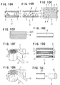
- Fig. 1A is a perspective view of a plain sheet to be prepared;
- Fig. 1B is a perspective view of a corrugated sheet during being passed through a pair of toothed gears;
- Fig. 1C is a front view of Fig. 1B;
- Fig. 1D is a plan view of a processed corrugated sheet;
- Fig. 1E is a schematic side view of a processed corrugated sheet;
- Fig. 2A is a perspective view of sheets during winding wherein a single plain sheet is used (single structure);
- Fig. 2B is a perspective view of sheets during winding wherein two plain sheets are used at the first part of a sheet roll and then a single plain sheet is used (semi-double structure);
- Fig. 2C is a perspective view of sheets during winding wherein two plain sheets are used for all portions of the sheet roll (double structure);
- Fig. 3A is a perspective view of a cylinder;
- Fig. 3B is a perspective exploded view of a catalyst carrier during diffusion bonding;
- Fig. 3C is a perspective view of a completed carrier;
- Fig. 4A is a sectional side view of the carrier, partially cut out;
- Fig. 4B is a sectional side view of the carrier in use;
- Fig. 5A is a sectional plan view of the main part of the carrier;
- Fig. 5B is a sectional side view of the main part of the carrier;
- Fig. 5C is a sectional front view of the carrier;
- Fig. 5D each is a view for explaining oxide layers;
- Fig. 6A is a sectional front view of the carrier brazed to a cylinder;
- Fig. 6B is a sectional front view of the carrier diffusion bonded to a cylinder;
- Figs. 6C to 6F each is a sectional front view of embodiments where each of the paired bonding assistants faces to other;
- Figs. 6G to 6J each is a sectional front view of embodiments where each of the paired bonding assistants is shifted to the other;
- Fig. 7A is a perspective view of a carrier on which a weight is placed for strength tests;
- Fig. 7B is a graph showing the relationship between the thickness of bonding assistants and the carrier strength;
- Fig. 8A is a graph showing the relationship between the number of assistants and the carrier strength;
- Fig. 8B is a graph showing the relationship between the ratio of the total width of assistants to the width of sheets and the carrier strength;
- Fig. 9A is a graph showing the relationship between the width of a single assistant and the carrier strength;
- Fig. 9B is a graph showing the relationship between the number of assistants and the carrier strength;
- Figs. 10A through 10I each shows prior arts and wherein
- Fig. 10A is a sectional plan view of the first example of prior art sheets;
- Fig. 10B is a sectional side view of the first example of the prior art;
- Fig. 10C is a sectional front view of the first example of the prior art;
- Fig. 10D is a front view of the second example of the prior art at production;
- Fig. 10E is a sectional plan view of a corrugated sheet of the second example of the prior art;
- Fig. 10F is a perspective view of the sixth example of the prior art at production;
- Fig. 10G is a sectional plan view of the sixth example of the prior art;
- Fig. 10H is a perspective view of the seventh example of the prior art at production; and
- Fig. 10I is an explanatory view of inserting carrier of the seventh example into a cylinder.
-
-
Catalyst carrier 14 of the invention is produced by the steps of 1. preparingsheets bonding assistants catalyst carrier 14. The invention is explained with each of the steps above. - Figs. 1A through 1E are referred to.
Corrugated sheet 1 andplain sheet 2 ofcatalyst carrier 14 are made from a thin foil stainless steel sheet having a 200 µ m, 100 µ m or 50 µ m thickness. A ferrite stainless steel containing aluminum, such as Fe-20Cr-5AI alloy and Fe-18Cr-3AI alloy are typically used because the sheets are used in a high temperature atmosphere and at a portion where heated and cooled conditions are repeated. - The surfaces of
corrugated sheet 1 andplain sheet 2, i.e., the surface of ferrite stainless steel, are covered by a protective oxidized film of Cr2O3. But the film is reduced at a temperature range at 800° C or higher, whereby it loses its protecting properties to oxidation. Therefore, the film on the surfaces of the sheets contains Al2O3 (alumina) in addition to Cr2O3. Al2O3 is not reduced even at a high temperature of 1,200 ° C or higher whereby it preventssheet -
Plain sheet 2 is produced by unrolling a roll to a plain belt of a 10 mm to 150 mm width, and by cutting the belt to a suitable length, as shown in Fig. 1A. -
Corrugated sheet 1 is produced by passingplain sheet 2 obtained by unrolling a roll between a pair oftoothed gears 5 under heat and pressure, as shown in Figs. 1B, 1C, 1D and 1E. Producedcorrugated sheet 1 has repeated waves having a predetermined height running widthwise, with a width L of 10mm to 150 mm, and is cut to a certain length. Width L and the length ofcorrugated sheet 1 are same as those ofplain sheet 2. - The cross section of the wave is typically a triangle having a dull edge.
- Width M of
toothed gears 5 is wider than width L ofsheet corrugated sheets 1 of various widths L. That is, a pair ofgears 5 having about 200 mm width can processplain sheets 2 of a width of 150mm, 100mm, 75mm, 50mm, etc. - The wave of
corrugated sheet 1 processed bytoothed gears 5 has, inevitably, a form shown by a sectional plan view shown in Fig. 1D. That is,corrugated sheet 1 has a pitch at right and left ends narrower than that at the center portion, andprojections 6 projected from the right and left ends are formed thereby. The projection has a shape of gently sloping triangular half.Projection 6 has width N of about 5mm starting from the beginning of the slope, and height H of about 15µ m. In other words,projection 6 starts from about 5mm (width N) inside the right and left ends, and projects about 15µm (height H) from the center portion. - Figs. 2 and 5 are referred to.
Bonding assistant 15 is used in windingstep 3, mentioned later, and functions as a bonding portion at a diffusion-bonding step mentioned later. The assistant can be made of various types of stainless steel. When it is made of normal ferrite such as SUS 430 and SUS 409, a higher diffusion speed is obtained whereby thediffusion bonding step 4 proceeds swiftly. On the other hand, when it is made of normal austenite type stainless steel such as SUS 304 and SUS 309 having a greater thermal expansion coefficient, the contact pressure between thecorrugated sheet 1 and theplain sheet 2 is increased. Thus, the assistant which is excellent in bonding strength is obtained. - When
sheets bonding assistant 15, chromium and aluminum components are diffused fromsheet assistant 15. As the result,assistant 15 is integrated to the sheets and a protective layer of Cr2O3 and/or Al2O3 are formed whereby the bonding portions become oxidation resistant. - When bonding
assistant 15 is made of a material same as that of the sheets, that is, when the assistant is made of ferrite type stainless steel, Fe-Cr-AI alloy, it shows most strong oxidation resistant properties. -
Assistant 15 is a thin belt having a thickness T of from 20 to 200µm, generally 30 to 50µm. In Fig. 5A,assistant 15 has thickness T of 20µm or more which is thicker than around 15µm height H ofdiffusion projection 6 formed at side ends ofcorrugated sheet 1 as mentioned earlier.Assistant 15 is used as a bonding portion betweensheets sheets -
Assistant 15 has width W of 0.5 to 5mm, because the practical smallest value of width W of a stainless steel band, which can be cut in consideration of cost, is 0.5mm. Therefore, width W is 0.5mm or more, and 5mm or less because if it is greater than 5mm, the contact pressure betweensheets shape bonding assistant 15 of such thickness T and width W has a length substantially similar to those ofsheet - Figs. 2, 5 and 6 are referred to. At the winding step,
stainless steel sheets assistants 15 therebetween are wound to form a roll. - As will be clear from Figs. 2A to 2C,
corrugated sheet 1, one or moreplain sheets 2 of a length same as that ofsheet 1, and one or morethin diffusion assistants 15 are superimposed with each other. Then they are wound to form a round roll of multiple layers. - Specifically, Fig. 2A shows a single plain sheet structure, which is most often used, comprising single
corrugated sheet 1 and singleplain sheet 1. Fig. 2B shows a semi-double plain sheet structure wherein singlecorrugated sheet 1 and twoplain sheets 2 are used at the outer portion of the roll while onesheet 1 and oneplain sheet 2 are used at the inner portion. That is, one plain sheet is used to partway and then twoplain sheets 2 are used. Fig. 2C shows a double plain sheet structure wherein onecorrugated sheet 1 and twoplain sheets 2 at all windings. In Figs. 2B and 2C, a two plain sheets winding is shown by a thick line while one plain sheet winding is shown by a thin line. -
Catalyst carrier 14 of the semi-double or double structure is used in the case where the carrier is strongly trembled and thermally stressed and, therefore, high tremble resistant properties and high thermal stress easing properties are required. In the semi-double or double structure, no local contacting pressure is produced between twoplain sheets 2 and the sheets are not diffusion bonded to each other, though a contacting pressure betweencorrugated sheet 1 andplain sheets 2 are maintained. Therefore, since the plain sheets slide on each other, the structure is improved in the tremble-resistant and thermal stress easing properties. -
Bonding assistant 15 normally is not put between plain sheets for these structures. In some case, even a bonding preventive agent is coated to plain sheets. However, whencatalyst carrier 14 is weak in maintaining its shape such as when axial width L ofsheet sheets 2 to improve the shape-maintaining properties. - To put
assistant 15 betweensheets projection 6. As has been described,projections 6 are formed about 5mm (width N) inside the ends ofsheet 1. To be away fromprojections 6,assistants 15 are positioned more than 5 mm inside the ends. -
Bonding assistants 15 are used in pair or pairs via plain sheet orsheets 2, as shown in Figs. 2A-2C, 5A and 6. The total width of the assistant or assistants is 0.3 to 20% of width L ofsheet -
Assistant 15 has 0.5 to 5 mm width W as discussed previously and a single or a plurality number of assistants may be used in pair or pairs. - The total of width W of assistants15 is regulated by width L of
sheet sheet catalyst carrier 14 is normally 150 mm. Therefore, the minimum ratio of the assistant to width L is calculated by a formula (0.5/150) x 100, i.e., 0.3 %. The ratio of the total should be 20% or less. If the ratio is over 20%, the contacting pressure betweensheets - Sets or pairs of
bonding assistant 15 are used to holdplain sheet 2 therebetween. Figs. 6A through 6F show paired assistants face to each other viasheet 2, whereby the pressure betweencorrugated sheet 1 andplain sheet 2 is strengthened. When a bonding assistant at one side ofplain sheet 2 faces to that at the other side, the contacting pressure and, accordingly, the contacting strength will be increased. Therefore,catalyst carrier 14 of this type is suitably used for a two-wheeled vehicle such as a motor scooter whose carrier is strongly trembled and has weak thermal stress. - On the contrary, paired
assistants 15 shown in Figs. 6G through 6J do not face to each other, but are shifted to each other viaplain sheet 2, whereby the thermal stress easing properties betweensheets Catalyst carrier 14 of this type is used suitably for a four-wheeled vehicle whose carrier is not strongly trembled and receives repeating thermal stress. - When the catalyst carrier is strongly trembled and receives high thermal stress, there may be used the facing pairs or shifting pairs of
assistants 15 in combination with previously mentioned semi-double or double structure ofplain sheets 2. -
Catalyst carrier 14 used for a strongly trembled vehicle should have bonding surface area as large as possible. For that purpose, the bonding assistant should have greater width W while the number of the assistants used is reduced. On the contrary,carrier 14 used for a vehicle, whose carrier receives strong thermal stress, should receive less stress at each bonding portion to improve the stress easing properties. Therefore,assistants 15 having narrower width W are used and the number of the assistants used are increased. - Figs. 3A to 3C are referred to. In this step,
sheets step 3 mentioned above, are bonded to each other at bonding positions. -
Rolled sheets corrugated sheet 1. - A roll of
sheets assistants 15 are inserted intocylinder 10 shown in Fig. 3A. The sheets are smoothly inserted without receiving any particular pressure betweencylinder 10 and the roll. -
Cylinder 10 of stainless steel for example, has slit 17, which may be welded before or after the insertion of the sheets. A seamless pipe may be used ascylinder 10. - The roll of
sheets assistants 15, inserted intocylinder 10, is transferred intovacuum furnace 19 havingheaters 18 as shown in Fig. 3B and are subjected to a diffusion bonding step. - The diffusion bonding is carried out in reduced-pressure or deoxidation atmosphere such as in a vacuum, in an argon or inert gas atmosphere, at a temperature between 1,150 to 1,300° C. The process is carried out for 30 minutes to 3 hours. When it is carried out at a high temperature, the time required is shortened while at a low temperature, the time is prolonged. By the heat applied,
corrugated sheet 1 is expanded to the direction vertical to the axial direction whereby a locally high contacting pressure is exerted betweenbonding assistants 15 andsheet 1 and between the assistants andsheet 2, Thus, a high pressure necessary for the diffusion bonding is obtained. - By the process above, the diffusion bonding is effected between
corrugated sheet 1 at the top and bottom portions and the corresponding portions ofbonding assistant 15, and betweenplain sheet 1 and all surfaces of the assistants (Figs. 5A, 5B and 5C). Consequently,sheets corrugated sheets 1,plain sheets 2 andassistants 15, whereby the contacting portions ofsheets - In
bonding sheets cylinder 10 via the assistants,brazing agent 20 may be used as shown in Fig. 6A, since the temperature at the portion nearcylinder 10 is relatively low in comparison to that at the core portion ofcarrier 14. -
Catalyst carrier 14, shown in Figs. 3C and 5A through 5C, for use in exhaustgas cleaning system 16 is produced by the steps of 1) preparingsheets bonding assistants 15, 3) winding and 4) diffusion bonding. - The carrier comprises a roll of
sheets cellular spaces 4. - That is, the carrier has a roll shape and a honeycomb structure and is inserted in
cylinder 10. A typical roll has a shape of a circular cross-section as shown in Fig. 3A, but the roll may have a form of an elliptical or angular cross-section. - The honeycomb structure comprises a number of hollow columns of cellular spaces, defined by cell walls of
corrugated sheets 1 andplain sheets 2, with open column ends. Cell walls andcell spaces 4 have substantially triangular shapes with dull edges in cross-section as shown in Fig. 4A, but they may have trapezoidal or other shapes. - The honeycomb structure is excellent in the strength to weight, is light-weighted, and has high rigidity and strength. Further, it has good rectifying effect, has a great surface area per unit volume, and other excellent features.
- According to the invention,
catalyst carrier 14 uses the effect of the great surface area per unit volume.Catalyst material 21 is adhered to the surfaces ofsheets bonding assistants 15 which constitutecell walls 4 as shown in Fig. 4A. Fig. 4B shows that a greater area for the contact between passingexhaust gas 22 andcatalyst material 21 is obtained and that the harmful substance contained inexhaust gas 22 is reacted withcatalyst material 21 and is removed, and thereby the exhaust gas is purified. -
Catalyst carrier 14 is used under the condition where hightemperature exhaust gas 22 passes and where heat is generated by the catalytic reaction. It is used in exhaustgas purifying system 16 for two wheeled cars such as auto-bikes and motor scooters, four wheeled cars, chain saws, and other internal combustion engines. -
Catalyst material 21 is selected from materials such as noble metals which react with harmful substance such as carbon monoxide, nitrogen oxide and hydrocarbon, and is coated on the alumina-containing surface ofsheets - Belt-
like sheets Corrugated sheet 1 hasdiffusion projections 6 at both side ends of the top and bottom portions, which are formed whensheet 1 passes through a pair of toothed gears 5.Projection 6 has a substantially triangular pyramid having width N of about 5mm and height H of about 15µm, see Fig. 1D. Bonding assistant15 used forcarrier 14 is made of stainless steel and has a length similar to those ofsheets -
Assistants 15 are located radially inside the positions ofprojections 6 formed at the left and right hand ends of thesheet 1 and have thickness T greater than height H ofprojections 6, see Fig. 5A. They are located 5mm or more inside the side ends ofsheets plain sheet 2, one or a plural numbers in each side ofsheet 2, with width W of 0.5 to 5mm and the total width of the assistants being 0.3 to 20% of width L ofsheet plain sheet 2 increase the contacting pressure betweenplates - According to the present invention,
catalyst carrier 14 are produced by the steps of 1) preparingsheets bonding assistants 15, 3) winding and 4) diffusion bonding.Sheets assistants 15 therebetween, and producedcarrier 14 has the features below. - First,
sheets bonding assistants 15 with locally strong contacting pressure, without the influence ofprojections 6 formed at side ends ofsheet 1. That is, the top and the bottom ofsheet 1 are diffusion bonded under high contacting pressure toplain sheet 1 by usingbonding assistants 15, not by contact at points, but by contact at short lined areas. The assistants are located at predetermined positions and have predetermined thickness T and width W. Therefore, they are not influenced byprojections 6 when pressed, receive high pressure whencorrugated sheet 1 is expanded under heat, and receive locally centered pressure at short lined areas, see Figs. 5A and 5C. - Consequently,
catalyst carrier 14, whosesheets - Second, the excellent properties are easily realized by only holding
bonding assistants 15 with predetermined thickness T and width W at predetermined positions andcarrier 14 is easily produced as discussed below. - According to the invention, conventional toothed gears 5 are used to produce
corrugated sheets 6 havingdiffusion projections 6 at side ends, see Fig.1, and no specialtoothed gears 8 as shown in Fig. 10D is needed and there is no need to removeprojections 6 fromcorrugated sheets 8, as shown in Fig. 10E. - At the diffusion-bonding step, the roll of
sheets cylinder 10 without being strongly pressed, as shown in Fig. 3. -
Corrugated sheet 1 having an approximately triangular shape with dull ends (tops) are used for the invention. Therefore no special procedure is necessary, such aspressing sheet 1 to remove the projections or using a sheet having no dull ends. Further, no procedure to remove surface roughness ofsheet 1 is needed since a high contact pressure for strong bonding is obtained by the use ofassistants 15. -
Sheets cylinder 10, as discussed above. Sincecorrugated sheet 1 expands by heat, high contact pressure is applied locally to positions where the sheet contacts the bonding assistants and the diffusion bonding proceeds with a sufficient bonding strength. There is no need to provide a further process to obtain sufficient contact pressure for the diffusion bonding. - The bonding step itself is simple. As discussed above, a contact pressure necessary for the diffusion bonding is obtained locally by the use of
bonding assistants 15, and no strict control on the atmosphere, temperature and time is needed. - A protective oxidized layer, Al2O3, is formed on the surface of
sheets - The protective oxidized layer Al2O3 is quite thin (5µm or less) and is broken under heat. Therefore, the layers of
sheets - According to the invention, a high contacting pressure is locally obtained to bond the sheets by using
bonding assistants 15, the processing conditions need not be strictly controlled. That is, the diffusion bonding process can be carried out in wide range of low pressure or reduction conditions, at relatively low temperature and in relatively short time. Thus, the diffusion bonding process can be simplified according to the invention. - In examples below, the strength of
catalyst carrier 14 as shown in Fig 3C was tested using bonding assistants of various thickness T and width W as illustrated in Fig. 5A. The strength herein means the resistance to passing through the carrier or shearing strength betweensheets - Diameter () of carrier 14: 60 mm
- Number of cells: 310,000 cells/m2 (200 cells /inch2)
- Thickness of
sheets 1 and 2: 50µm - Diameter () of penetrator 24: 40 mm
-
- The strength test was carried out as follows.
-
Catalyst carrier 14 comprising a sheet roll incylinder 10 was placed lengthwise on shortcylindrical holder 23, see Fig. 7A. The holder has a diameter and a thickness same as those ofcylinder 10 and supports the cylinder but do not carry an inner roll. -
Penetrator 24 having a short cylindrical shape and a diameter smaller than that ofcarrier 14 was placed on the open top of the catalyst carrier, and was pressed at various load from above. - In Figs. 7B, 8A, 8B and 9A showing the test results of Examples 1,2,3 and 4, respectively. Broken lines show the test results of
conventional catalyst carriers 3 which do not use bonding assistants, carried out under same conditions. The results demonstrate thatcatalyst carriers 14 of Examples 1 through 4, which use bonding assistants, are far much stronger thanconventional carriers 3. - Fig. 7B shows the test results of the carrier strength when thickness T of
bonding assistants 15 is varied. Supplemental data is as follows: - Overall shape: 60 mm x width L 60 mm
- Bonding assistant: 5 mm width W x T (2 pairs of two assistants)
-
- That is,
catalyst carrier 14 has a diameter of 60mm and width L of 60 mm, i.e.corrugated sheet 1 and ofplain sheet 2 have width L of 60 mm. Bonding assistants held between sheets have width W of 5 mm and are used such that two pairs of two assistants each face to each other viaplain sheet 2. - Fig. 7B shows that the penetrating strength or sheering strength mentioned earlier was reduced when thickness T of
bonding assistant 15 is 15µm, since it is equal to height H, i.e., 15µm, oftriangular projection 6 formed at side ends ofcorrugated sheet 1. That is, the bonding or contacting pressure between sheets was reduced because it was dispersed to two short lined areas of contact of two assistants withplain sheet 2, and to two points at tops ofprojection 6. - When thickness T of
assistants 15 is over 15µ m and less than 20µm, a sufficient strength was obtained, since the pressure was centered to only two short line areas of contact of two assistants withplain sheet 2. - When thickness T is over 200µm, the strength is lowered again, since gap U between
assistants 15 corresponding to thickness T (see Figs. 6A and 6B) becomes too great to maintainsheets bonding assistant 15 should be from 20 to 200µm. - In this example, the bonding or contacting strength was tested by varying width L of
carrier 14 to obtain values shown in Fig. 8A. Supplemental data is as follows: - Overall shape: 60 mm x width L
- Bonding assistant: 5 mm width W x 100µm thickness T
-
- That is, width L, i.e., the axial length of
catalyst carrier 14 which corresponds to radial width L ofsheets bonding assistants 15 held between sheets which have width W of 5 mm and thickness T of 100µm were used. - When one
bonding assistant 15 was held betweensheets carrier 14 was reduced when width L is less than 25mm, as will be seen from Fig. 8A. When two assistants were used, the strength was reduced in the case where width L is less than 50 mm. When three assistants were used, the strength was reduced in the case of less than 75 mm and when four assistants were used, and the strength was reduced in the case of less than 100 mm. - From the results of Example 2, it was revealed that the total width of assistants, i.e., the total of each width W of all the assistants including one assistant held between sheets, is regulated by width L of
carrier 14 which corresponds to width L ofsheets
ofassistants 15 is regulated by width L ofsheets - Example 3 was obtained based on the results of Example 2. Fig. 8B shows the results of the total of each width W of all bonding assistants to width L of
carrier 14 corresponding to sheet width L, to load. The data conditions of Example 3 are same as that of Example 2. - As discussed, the total of each width W of assistants is regulated by width L of
sheets 1 and 2 (width L of carrier 14). If not, the pressure is not centered, resulting in insufficient bonding strength between sheets. - Fig. 8B shows that the strength is reduced when the total width of each width W of
assistants 15 is over 20% of width L of sheets and it was revealed that the total width should be less than 20% of width L of sheets. - Since minimum width W is 0.5 mm and the minimum number of the assistant is one and since maximum width L of sheets is 150 mm, the minimum value of total width of each of assistants to sheet width L is calculated by a formula (0.5/150) x 100 = 0.3 %. It was revealed, therefore, the ratio of the width total of assistants to sheet width L is 0.3% or more and 20% or less.
- Width W of
bonding assistants 15 was varied and the strength ofcarrier 14 was measured to produce Fig. 9A. Supplemental data is as follows: - Overall shape: 60 mm x 150 mm width L
- Bonding assistant: width W x 100µm thickness T (two pairs of one
assistant)
That is,catalyst carrier 14 has a diameter of 60mm and width L of 150 mm, i.e. width L ofcorrugated sheet 1 and ofplain sheet 2 is 150 mm. Bonding assistants held between sheets have thickness T of 100µm and one assistant per each surface ofplain sheet 2, is used such that a pair of assistants face to each other viaplain sheet 2. For this Example 4,carrier 14 with assistants having various width W was tested. -
- If one
assistant 15 having width W of 30 mm is used forcarrier 14 having width L (sheet width L) of 150mm, the ratio according to the calculation formula of Example 3 is 20% and sufficient strength should be obtained. However, according to Fig. 9A showing the results of Example 4, sufficient strength was obtained for assistants having width W of 5 mm or less. If width W is over 5mm, the strength ofcarrier 14 is reduced. The reason can be thought as follows. - As has been discussed, locally centered pressure should be applied to the contact portion of
assistant 15, provided betweensheets carrier 14 is increased,assistant 15 will be broken prior to the time when sheets is broken, and the sheets will not be broken. In this instance, therefore, thebonding assistant 15 is broken and cut at the bonding interface. - Contrary to this, when width W is 5mm or less and if the weight is increased,
sheets time assistant 15 is broken and the assistant will not be broken. That is, whenassistant 15 having 5mm or less width is used, a strength greater than that at breaking point of sheets is not obtained and, thus, the strength at 5mm or less is relatively constant, as shown in Fig. 9A. - From the result above, it was revealed that width W of bonding assistant W should be 5mm or less. Naturally, the minimum width is 0.5mm and the value of the total width should be 20% or less to that of carrier width L, as discussed in Example 3.
- In Example 5, the number of bonding assistants was varied to produce the results shown in Fig. 9B. Supplemental data is as follows:
- Overall shape: 60 mm x 150 mm width L
- Bonding assistant: 100µm thickness T
-
- That is,
catalyst carrier 14 has a diameter of 60mm and width L (sheet width L) of 150 mm.Bonding assistants 15 held betweensheets plain sheet 2. For this example, the number (row) of the assistants used was changed while the total width of assistants was arranged same to all carriers and the strength ofcarrier 14 was measured. - It was revealed that the carrier strength was not different between the case where one assistant having a relative width of 5 was used and the case where five assistants having a relative width of 1 were used. This result shows that if the total width of assistants is same, the strength of carriers and the shearing strength or boding strength of sheets are same even if the number of the assistants used is different.
- The catalyst carrier for an exhaust gas clearing system of the invention is produced by holding thin-belt like bonding assistant or assistants between broader-belt like corrugated sheet and plain sheet, wherein the assistants are positioned radially inside the projections formed at ends of the corrugated sheet, with a thickness greater than the height of projections and with a predetermined width. With the above feature, the carrier of the invention has following technical advantages.
- First, the catalyst carrier is excellent in the strength with regard to trembling resistant and heat-resistant properties and thermal stress easing properties. According to the invention,
sheets - The
catalyst career 14 is composed ofsheets bonding assistants 15 of stainless steel and an oxidized protective layer is surely produced on the surfaces of the sheets as shown in 5D. Therefore, the carrier has excellent oxidation resistant properties and is improved in heat resistant properties and heat resistant strength. Thus, also from this point, the carrier is most suitable for high temperature gas exhaust devices, and for two and four wheeled cars. - According to the carrier, the sheets are not diffusion bonded at all surfaces, but only at the linear portion of the contact of the bonding assistants with sheets and, therefore, thermal stress easing properties between bonded sheets are improved. Particularly, the properties are improved when each of the pair of bonding assistants is shifted to other via a plain sheet.
- Second, the advantageous effect mentioned above can be realized in a simple manner, since the catalyst carrier can be produced by holding bonding assistants of a predetermined thickness and a width, at predetermined positions between sheets. The advantageous cost performance can be discussed as follows:
- a. According to the invention, there is no need to prepare a number of special toothed gears to remove projections, which have been necessary for a conventional process. Since generally used gears can be used and corrugated sheets having projections are processed without a projections-removing process.
- b. There is no need to apply pressure to a roll of sheets with bonding assistants when the roll is inserted into a cylinder as has been necessary in the conventional process. According to the invention, the roll is simply inserted into the cylinder and no high skill therefor is necessary.
- c. There is no need to repeat a pressing work for removing the projections, to use flat corrugated sheets having no projections or to process sheets for flattering the surface roughness. According to the present invention, generally used corrugated sheets, which have bending portions, can be used without further process.
- d. There is no need to form a throttled portion stated previously as fifth prior art example. Therefore, no instrument therefor is necessary and there is no fear that the corrugated shape may be destructed.
- e. There is no strict control on atmospheric conditions, temperature and time since high contacting pressure is applied to sheets during diffusion bonding.
-
- Accordingly, defects suffered in the conventional process are all overcome according to the present invention.
Claims (7)
- Catalyst carrier 14 for exhaust gas purification system 16, comprising bands of stainless steel-made at least one corrugated sheet 1 and at least one plain sheet 2 which hold stainless steel-made bonding assistants 15 therebetween,wherein said bonding assistants 15 have a width narrower than those of sheets 1 and 2,wherein said sheets are alternated and are wound to form a roll having a honeycomb structure comprising a number of cell spaces 4,wherein catalyst materials 21 are adhered to sheets,wherein said sheets 1 and 2 are diffusion bonded to each other via bonding assistants 15,wherein said bonding assistants 15 are positioned radially inside from projections 6, which are formed at side ends of corrugated sheet 1 during passing sheet 1 through a pair of toothed gears 5, andwherein said bonding assistants 15 have thickness T greater than height H of projections 6.
- A catalyst carrier according to claim 1, comprising one corrugated sheet 1 and one plain sheet 2, each being made of stainless steel containing aluminum, wherein said sheets 1 and 2 have substantially same length and width L, and the length of assistants 15 is substantially same as that of sheets 1 and 2.
- A catalyst carrier according to claim 1, wherein assistants 15 are positioned 5mm or more inside the side ends of sheets 1 and 2, and have thickness T of from 20 to 200µm.
- A catalyst carrier according to claim 3, wherein assistants 15 are used in a pair or pairs via plain sheet 2, and wherein width W of one assistant is 0.5 to 5 mm, and ratio of the total width of all assistants to width L of sheets 1 and 2 is 0.3 to 20%.
- A catalyst carrier according to claim 4, wherein each of the pair or pairs of assistants 15 face to the other via plain sheet 2 to increase the contact pressure between sheets 1 and 2.
- A catalyst carrier according to claim 4, wherein each of the pair or pairs of assistants 15 is shifted to the other via plain sheet 2 to improve thermal stress easing properties.
- A method for producing catalyst carrier 14 for exhaust gas purification system 16, comprising,winding bands of stainless steel-made at least one corrugated sheet 1 and at least one plain sheet 2 which hold stainless steel-made bonding assistants 15 therebetween, to form a roll, wherein said bonding assistants 15 have a width narrower than that of sheets 1 and 2, and said sheets are alternated,wherein said bonding assistants 15 are positioned radially inside from projections 6, which are formed at side ends of corrugated sheet 1 during passing sheet 1 through a pair of toothed gears 5, andheating the roll to diffusion bond the sheets 1 and 2 to each other via bonding assistants 15, to produce the roll having a honeycomb structure comprising a number of cell spaces 4, andadhering a catalyst material 21 to sheets 1 and 2 and bonding assistants 15.
Applications Claiming Priority (2)
| Application Number | Priority Date | Filing Date | Title |
|---|---|---|---|
| JP2000141356 | 2000-05-15 | ||
| JP2000141356A JP3790089B2 (en) | 2000-05-15 | 2000-05-15 | Catalyst carrier for exhaust gas purification device and method for producing the same |
Publications (3)
| Publication Number | Publication Date |
|---|---|
| EP1156196A2 true EP1156196A2 (en) | 2001-11-21 |
| EP1156196A3 EP1156196A3 (en) | 2002-12-11 |
| EP1156196B1 EP1156196B1 (en) | 2004-11-10 |
Family
ID=18648483
Family Applications (1)
| Application Number | Title | Priority Date | Filing Date |
|---|---|---|---|
| EP01301035A Expired - Lifetime EP1156196B1 (en) | 2000-05-15 | 2001-02-06 | Catalyst carrier for exhaust gas purification system and method for producing same |
Country Status (7)
| Country | Link |
|---|---|
| US (1) | US6841135B2 (en) |
| EP (1) | EP1156196B1 (en) |
| JP (1) | JP3790089B2 (en) |
| DE (1) | DE60107011T2 (en) |
| ES (1) | ES2228754T3 (en) |
| ID (1) | ID30195A (en) |
| TW (1) | TW497984B (en) |
Cited By (2)
| Publication number | Priority date | Publication date | Assignee | Title |
|---|---|---|---|---|
| WO2007031331A1 (en) * | 2005-09-16 | 2007-03-22 | Emitec Gesellschaft Für Emissionstechnologie Mbh | Method and device for applying hard solder |
| US8288010B2 (en) | 2009-04-24 | 2012-10-16 | Emitec Gesellschaft Fuer Emissionstechnologie Mbh | Sheet-metal layer with anti-diffusion structures and metallic honeycomb body with at least one such sheet-metal layer |
Families Citing this family (10)
| Publication number | Priority date | Publication date | Assignee | Title |
|---|---|---|---|---|
| US20030068259A1 (en) * | 2001-09-15 | 2003-04-10 | Shahrokh Etemad | Stacked catalytic reactor |
| DE102004058285A1 (en) * | 2004-12-02 | 2006-06-08 | Emitec Gesellschaft Für Emissionstechnologie Mbh | Connecting material for positioning of solder material, method for producing a honeycomb body and corresponding honeycomb body |
| WO2010029978A1 (en) * | 2008-09-10 | 2010-03-18 | 株式会社 キャタラー | Catalyst for exhaust gas purification |
| KR101063759B1 (en) | 2009-07-09 | 2011-09-08 | 한국가스안전공사 | Anti-Inflammation Element for Flashback Arrestor |
| US8236084B2 (en) * | 2009-08-18 | 2012-08-07 | Corning Incorporated | Ceramic radial wall flow particulate filter |
| DE112014001875T5 (en) | 2013-04-09 | 2015-12-24 | Aktiebolaget Skf | Bearing part and its manufacturing process |
| DE112014001903T5 (en) * | 2013-04-10 | 2015-12-31 | Aktiebolaget Skf | Method for joining two materials by diffusion bonding |
| US9383143B2 (en) * | 2013-09-26 | 2016-07-05 | Micro Cooling Concepts, Inc. | Metallic thin-film bonding and alloy generation |
| WO2017072137A1 (en) * | 2015-10-28 | 2017-05-04 | Haldor Topsøe A/S | Honeycomb catalyst for removal of nitrogen oxides in flue and exhaust gasses and method of preparation thereof |
| EP3833857B1 (en) * | 2018-08-10 | 2023-03-22 | Honda Motor Co., Ltd. | Catalytic device |
Citations (2)
| Publication number | Priority date | Publication date | Assignee | Title |
|---|---|---|---|---|
| JPH0739765A (en) | 1993-08-03 | 1995-02-10 | Toyota Motor Corp | Manufacture of catalyst container with metal carrier |
| JPH08281123A (en) | 1995-04-18 | 1996-10-29 | Calsonic Corp | Metal catalyst carrier unit |
Family Cites Families (9)
| Publication number | Priority date | Publication date | Assignee | Title |
|---|---|---|---|---|
| DE2924592C2 (en) * | 1979-06-19 | 1983-05-26 | Süddeutsche Kühlerfabrik Julius Fr. Behr GmbH & Co KG, 7000 Stuttgart | Method for producing a carrier matrix for a catalytic reactor for exhaust gas purification in internal combustion engines of motor vehicles |
| JPH0616855B2 (en) * | 1988-07-22 | 1994-03-09 | 日本冶金工業株式会社 | Supported matrix for catalytic reactors |
| JP3047402B2 (en) * | 1988-08-13 | 2000-05-29 | 臼井国際産業株式会社 | Thin-walled steel sheet and its manufacturing method |
| JP2553733B2 (en) * | 1990-04-17 | 1996-11-13 | 昭和飛行機工業株式会社 | Heat resistant structure |
| JP2509478B2 (en) * | 1991-05-09 | 1996-06-19 | 昭和飛行機工業株式会社 | Honeycomb structure and manufacturing method thereof |
| DE4416539C1 (en) * | 1994-05-10 | 1995-07-20 | Emitec Emissionstechnologie | Method for applying solder to metal structures using solder powder |
| DE19530853A1 (en) * | 1995-08-22 | 1997-02-27 | Emitec Emissionstechnologie | Method for producing a honeycomb body from two differently constructed types of sheet metal |
| DE69721326T2 (en) * | 1997-05-09 | 2003-10-23 | Nippon Steel Corp | CATALYTIC METAL HONEYCOMB FOR EXHAUST GAS PURIFICATION AND PRODUCTION THEREOF |
| JP3720973B2 (en) * | 1998-03-16 | 2005-11-30 | 新日本製鐵株式会社 | Diffusion bonded metal carrier and manufacturing method thereof |
-
2000
- 2000-05-15 JP JP2000141356A patent/JP3790089B2/en not_active Expired - Fee Related
-
2001
- 2001-02-06 ES ES01301035T patent/ES2228754T3/en not_active Expired - Lifetime
- 2001-02-06 DE DE60107011T patent/DE60107011T2/en not_active Expired - Fee Related
- 2001-02-06 EP EP01301035A patent/EP1156196B1/en not_active Expired - Lifetime
- 2001-02-27 TW TW090104458A patent/TW497984B/en active
- 2001-03-21 US US09/814,428 patent/US6841135B2/en not_active Expired - Fee Related
- 2001-05-02 ID IDP00200100356D patent/ID30195A/en unknown
Patent Citations (2)
| Publication number | Priority date | Publication date | Assignee | Title |
|---|---|---|---|---|
| JPH0739765A (en) | 1993-08-03 | 1995-02-10 | Toyota Motor Corp | Manufacture of catalyst container with metal carrier |
| JPH08281123A (en) | 1995-04-18 | 1996-10-29 | Calsonic Corp | Metal catalyst carrier unit |
Cited By (3)
| Publication number | Priority date | Publication date | Assignee | Title |
|---|---|---|---|---|
| WO2007031331A1 (en) * | 2005-09-16 | 2007-03-22 | Emitec Gesellschaft Für Emissionstechnologie Mbh | Method and device for applying hard solder |
| US7823764B2 (en) | 2005-09-16 | 2010-11-02 | Emitec Gesellschaft Für Emissionstechnologie Mbh | Method and device for brazing material application, method for producing a honeycomb body, exhaust gas treatment unit and vehicle |
| US8288010B2 (en) | 2009-04-24 | 2012-10-16 | Emitec Gesellschaft Fuer Emissionstechnologie Mbh | Sheet-metal layer with anti-diffusion structures and metallic honeycomb body with at least one such sheet-metal layer |
Also Published As
| Publication number | Publication date |
|---|---|
| JP3790089B2 (en) | 2006-06-28 |
| JP2001321678A (en) | 2001-11-20 |
| ES2228754T3 (en) | 2005-04-16 |
| EP1156196B1 (en) | 2004-11-10 |
| TW497984B (en) | 2002-08-11 |
| US6841135B2 (en) | 2005-01-11 |
| ID30195A (en) | 2001-11-15 |
| EP1156196A3 (en) | 2002-12-11 |
| DE60107011T2 (en) | 2005-10-20 |
| DE60107011D1 (en) | 2004-12-16 |
| US20010043892A1 (en) | 2001-11-22 |
Similar Documents
| Publication | Publication Date | Title |
|---|---|---|
| EP1156196B1 (en) | Catalyst carrier for exhaust gas purification system and method for producing same | |
| EP0985450B1 (en) | Exhaust gas cleaning catalyst metal honey comb element and its manufacture | |
| US5620666A (en) | Exhaust gas cleaning metallic substrate | |
| US8722572B2 (en) | Metal catalyst substrate and its manufacturing method | |
| KR20100127298A (en) | Honeycomb body and process for producing a soldered honeycomb body | |
| KR910008726B1 (en) | Catalyst support for catalytic reactors | |
| JP2007260656A (en) | Method for manufacturing exhaust gas treatment apparatus | |
| JP3308075B2 (en) | Manufacturing method of heat-resistant structure | |
| JP3252459B2 (en) | Metal carrier for exhaust gas purification catalyst | |
| JPH08206513A (en) | Metallic carrier and its production | |
| JPH04150948A (en) | Metal carrier supporting exhaust gas purifying catalyst having intermittently bonded honeycomb part and preparation thereof | |
| JPH10337481A (en) | Metal carrier for catalyst converter and production thereof | |
| JPH07171420A (en) | Metallic carrier | |
| JPH0751579A (en) | Metal carrier for exhaust has purification catalyst | |
| JP3544451B2 (en) | Metal carrier for catalytic converter and method for producing the same | |
| JPH07308586A (en) | Metallic carrier | |
| JPH06154621A (en) | Production of metal carrier catalyst vessel | |
| JP2523701B2 (en) | Manufacturing method of honeycomb substrate for automobile exhaust gas purifying apparatus | |
| JPH08229411A (en) | Metal carrier for exhaust gas purifying catalyst | |
| JP2820444B2 (en) | Metallic support for catalysts with excellent thermal fatigue resistance | |
| JPH09201537A (en) | Metal catalyst carrier in catalytic converter and its preparation | |
| JPH08196917A (en) | Metal carrier and its manufacture | |
| JPH07171418A (en) | Metallic carrier | |
| JPH09215932A (en) | Metal carrier for exhaust gas purifying catalyst | |
| JPH07303841A (en) | Metallic support |
Legal Events
| Date | Code | Title | Description |
|---|---|---|---|
| PUAI | Public reference made under article 153(3) epc to a published international application that has entered the european phase |
Free format text: ORIGINAL CODE: 0009012 |
|
| AK | Designated contracting states |
Kind code of ref document: A2 Designated state(s): AT BE CH CY DE DK ES FI FR GB GR IE IT LI LU MC NL PT SE TR |
|
| AX | Request for extension of the european patent |
Free format text: AL;LT;LV;MK;RO;SI |
|
| PUAL | Search report despatched |
Free format text: ORIGINAL CODE: 0009013 |
|
| AK | Designated contracting states |
Kind code of ref document: A3 Designated state(s): AT BE CH CY DE DK ES FI FR GB GR IE IT LI LU MC NL PT SE TR |
|
| AX | Request for extension of the european patent |
Free format text: AL;LT;LV;MK;RO;SI |
|
| RIC1 | Information provided on ipc code assigned before grant |
Free format text: 7B 01J 35/04 A, 7B 23K 20/16 B, 7F 01N 3/28 B |
|
| 17P | Request for examination filed |
Effective date: 20030602 |
|
| AKX | Designation fees paid |
Designated state(s): DE ES FR GB IT |
|
| GRAP | Despatch of communication of intention to grant a patent |
Free format text: ORIGINAL CODE: EPIDOSNIGR1 |
|
| GRAS | Grant fee paid |
Free format text: ORIGINAL CODE: EPIDOSNIGR3 |
|
| GRAA | (expected) grant |
Free format text: ORIGINAL CODE: 0009210 |
|
| AK | Designated contracting states |
Kind code of ref document: B1 Designated state(s): DE ES FR GB IT |
|
| REG | Reference to a national code |
Ref country code: GB Ref legal event code: FG4D |
|
| REG | Reference to a national code |
Ref country code: IE Ref legal event code: FG4D |
|
| REF | Corresponds to: |
Ref document number: 60107011 Country of ref document: DE Date of ref document: 20041216 Kind code of ref document: P |
|
| PGFP | Annual fee paid to national office [announced via postgrant information from national office to epo] |
Ref country code: GB Payment date: 20050202 Year of fee payment: 5 |
|
| PGFP | Annual fee paid to national office [announced via postgrant information from national office to epo] |
Ref country code: FR Payment date: 20050208 Year of fee payment: 5 |
|
| PGFP | Annual fee paid to national office [announced via postgrant information from national office to epo] |
Ref country code: ES Payment date: 20050323 Year of fee payment: 5 |
|
| REG | Reference to a national code |
Ref country code: ES Ref legal event code: FG2A Ref document number: 2228754 Country of ref document: ES Kind code of ref document: T3 |
|
| ET | Fr: translation filed | ||
| PLBE | No opposition filed within time limit |
Free format text: ORIGINAL CODE: 0009261 |
|
| STAA | Information on the status of an ep patent application or granted ep patent |
Free format text: STATUS: NO OPPOSITION FILED WITHIN TIME LIMIT |
|
| 26N | No opposition filed |
Effective date: 20050811 |
|
| PG25 | Lapsed in a contracting state [announced via postgrant information from national office to epo] |
Ref country code: GB Free format text: LAPSE BECAUSE OF NON-PAYMENT OF DUE FEES Effective date: 20060206 |
|
| PG25 | Lapsed in a contracting state [announced via postgrant information from national office to epo] |
Ref country code: ES Free format text: LAPSE BECAUSE OF NON-PAYMENT OF DUE FEES Effective date: 20060207 |
|
| PGFP | Annual fee paid to national office [announced via postgrant information from national office to epo] |
Ref country code: IT Payment date: 20060228 Year of fee payment: 6 |
|
| GBPC | Gb: european patent ceased through non-payment of renewal fee |
Effective date: 20060206 |
|
| REG | Reference to a national code |
Ref country code: FR Ref legal event code: ST Effective date: 20061031 |
|
| REG | Reference to a national code |
Ref country code: ES Ref legal event code: FD2A Effective date: 20060207 |
|
| PG25 | Lapsed in a contracting state [announced via postgrant information from national office to epo] |
Ref country code: FR Free format text: LAPSE BECAUSE OF NON-PAYMENT OF DUE FEES Effective date: 20060228 |
|
| PGFP | Annual fee paid to national office [announced via postgrant information from national office to epo] |
Ref country code: DE Payment date: 20080131 Year of fee payment: 8 |
|
| PG25 | Lapsed in a contracting state [announced via postgrant information from national office to epo] |
Ref country code: IT Free format text: LAPSE BECAUSE OF NON-PAYMENT OF DUE FEES Effective date: 20070206 |
|
| PG25 | Lapsed in a contracting state [announced via postgrant information from national office to epo] |
Ref country code: DE Free format text: LAPSE BECAUSE OF NON-PAYMENT OF DUE FEES Effective date: 20090901 |