EP1156188B1 - Gas turbine with a leaf seal for the stator shroud - Google Patents
Gas turbine with a leaf seal for the stator shroud Download PDFInfo
- Publication number
- EP1156188B1 EP1156188B1 EP01300367A EP01300367A EP1156188B1 EP 1156188 B1 EP1156188 B1 EP 1156188B1 EP 01300367 A EP01300367 A EP 01300367A EP 01300367 A EP01300367 A EP 01300367A EP 1156188 B1 EP1156188 B1 EP 1156188B1
- Authority
- EP
- European Patent Office
- Prior art keywords
- shroud
- leaf seal
- spring
- seal
- groove
- Prior art date
- Legal status (The legal status is an assumption and is not a legal conclusion. Google has not performed a legal analysis and makes no representation as to the accuracy of the status listed.)
- Expired - Lifetime
Links
- 238000007789 sealing Methods 0.000 claims abstract description 17
- 239000007789 gas Substances 0.000 claims description 36
- 238000001816 cooling Methods 0.000 description 3
- 230000000295 complement effect Effects 0.000 description 2
- 230000001627 detrimental effect Effects 0.000 description 1
- 230000037361 pathway Effects 0.000 description 1
Images

Classifications
-
- F—MECHANICAL ENGINEERING; LIGHTING; HEATING; WEAPONS; BLASTING
- F01—MACHINES OR ENGINES IN GENERAL; ENGINE PLANTS IN GENERAL; STEAM ENGINES
- F01D—NON-POSITIVE DISPLACEMENT MACHINES OR ENGINES, e.g. STEAM TURBINES
- F01D9/00—Stators
- F01D9/02—Nozzles; Nozzle boxes; Stator blades; Guide conduits, e.g. individual nozzles
- F01D9/04—Nozzles; Nozzle boxes; Stator blades; Guide conduits, e.g. individual nozzles forming ring or sector
-
- F—MECHANICAL ENGINEERING; LIGHTING; HEATING; WEAPONS; BLASTING
- F01—MACHINES OR ENGINES IN GENERAL; ENGINE PLANTS IN GENERAL; STEAM ENGINES
- F01D—NON-POSITIVE DISPLACEMENT MACHINES OR ENGINES, e.g. STEAM TURBINES
- F01D11/00—Preventing or minimising internal leakage of working-fluid, e.g. between stages
- F01D11/005—Sealing means between non relatively rotating elements
-
- F—MECHANICAL ENGINEERING; LIGHTING; HEATING; WEAPONS; BLASTING
- F16—ENGINEERING ELEMENTS AND UNITS; GENERAL MEASURES FOR PRODUCING AND MAINTAINING EFFECTIVE FUNCTIONING OF MACHINES OR INSTALLATIONS; THERMAL INSULATION IN GENERAL
- F16J—PISTONS; CYLINDERS; SEALINGS
- F16J15/00—Sealings
- F16J15/02—Sealings between relatively-stationary surfaces
- F16J15/06—Sealings between relatively-stationary surfaces with solid packing compressed between sealing surfaces
- F16J15/08—Sealings between relatively-stationary surfaces with solid packing compressed between sealing surfaces with exclusively metal packing
- F16J15/0887—Sealings between relatively-stationary surfaces with solid packing compressed between sealing surfaces with exclusively metal packing the sealing effect being obtained by elastic deformation of the packing
-
- F—MECHANICAL ENGINEERING; LIGHTING; HEATING; WEAPONS; BLASTING
- F05—INDEXING SCHEMES RELATING TO ENGINES OR PUMPS IN VARIOUS SUBCLASSES OF CLASSES F01-F04
- F05D—INDEXING SCHEME FOR ASPECTS RELATING TO NON-POSITIVE-DISPLACEMENT MACHINES OR ENGINES, GAS-TURBINES OR JET-PROPULSION PLANTS
- F05D2240/00—Components
- F05D2240/10—Stators
- F05D2240/11—Shroud seal segments
-
- F—MECHANICAL ENGINEERING; LIGHTING; HEATING; WEAPONS; BLASTING
- F05—INDEXING SCHEMES RELATING TO ENGINES OR PUMPS IN VARIOUS SUBCLASSES OF CLASSES F01-F04
- F05D—INDEXING SCHEME FOR ASPECTS RELATING TO NON-POSITIVE-DISPLACEMENT MACHINES OR ENGINES, GAS-TURBINES OR JET-PROPULSION PLANTS
- F05D2240/00—Components
- F05D2240/55—Seals
-
- F—MECHANICAL ENGINEERING; LIGHTING; HEATING; WEAPONS; BLASTING
- F05—INDEXING SCHEMES RELATING TO ENGINES OR PUMPS IN VARIOUS SUBCLASSES OF CLASSES F01-F04
- F05D—INDEXING SCHEME FOR ASPECTS RELATING TO NON-POSITIVE-DISPLACEMENT MACHINES OR ENGINES, GAS-TURBINES OR JET-PROPULSION PLANTS
- F05D2260/00—Function
- F05D2260/30—Retaining components in desired mutual position
Definitions
- the present invention relates to a seal for sealing between a stator shroud and a leading edge of a nozzle wall along the outer band of a nozzle segment defining in part the hot gas path through the gas turbine.
- shroud segments are fixed to turbine shell hooks in an annular array to form an annular shroud radially outwardly and adjacent the tips of buckets forming part of the turbine rotor.
- the inner wall of the shroud defines part of the gas path.
- nozzles are hooked into the radial slots in the shroud segments.
- the cavities forward and aft of the shroud segments are at a higher pressure than the pressure of the gas path and significant leakage into the hot gas path frequently occurs.
- These cavities are typically pressurized by compressor discharge air and leakage of this air is detrimental to turbine performance and emissions. The leakage is compounded in those nozzle stages having non-continuous nozzle leading edge hooks.
- the gaps between the hooks and adjacent the edges of the shrouds provide large leakage paths for compressor discharge air to flow into the hot gas flow path. It is therefore desirable to provide a seal effective between the stator shroud segments and the nozzle wall, particularly in those turbines having non-continuous nozzle hooks, to minimize leakage flow into the hot gas path.
- US-A-5 797 723 discloses leaf seals biased into sealing engagement by leaf springs. However the leaf seals and springs are mounted on the nozzle segments and do not provide seals between adjacent stages of the turbine.
- US-A-5 118 120 discloses a U-spring with a first leg which contacts an outer rail of a nozzle and a second leg which contacts a leaf seal. However, a pin member is used which passes through the rail, spring and leaf members necessitating openings which provide pathways for leaking air out of the turbine unit.
- a turbine having a first stage and a following stage comprising a seal for sealing between a stator shroud and a nozzle of a multi-stage gas turbine to substantially preclude leakage between a pressurized cavity on one side of the seal and hot gases in a hot gas path of the gas turbine on the other side of the seal, comprising: a shroud segment having a surface for, in part, defining the hot gas path through one stage and overlying tips of buckets of said one stage forming part of a turbine rotor, said shroud segment having a leading edge and a trailing edge; an outer band for, in part, defining the hot gas path through an adjacent stage following said one stage and forming part of the nozzle of said adjacent stage; and a leaf seal between the trailing edge of said shroud segment and a leading edge side wall of said nozzle outer band; characterised in that said shroud segment has a groove for receiving said leaf seal; and a spring is carried by said groove in said shroud segment
- the leaf seal may be pivotally carried by the shroud for pivotal movement about an axis at a location spaced from the engagement between the leaf seal and the nozzle outer band.
- the leaf seal may extend in a generally radial direction for sealing engagement with the nozzle outer band.
- the seal may include an extension on an end of the leaf seal for overlapping a leaf seal of an adjacent shroud segment.
- the shroud segment may include an outer shroud and an inner shroud connected to one another with the surface forming part of the inner shroud, the leaf seal being secured to the inner shroud.
- the shroud segment may include an outer shroud and an inner shroud connected to one another with the surface forming part of the inner shroud, the leaf seal being secured to the outer shroud.
- the shroud segment may include a radially outwardly opening groove along a trailing edge thereof, the leaf seal and the spring seating in the groove with a face portion of the leaf spring projecting from the groove for engagement with the leading edge side wall of the nozzle outer band.
- the spring may include a generally U-shaped clip having a base and a pair of legs, the leaf seal being engaged by the spring clip between a leg thereof and a flange forming part of the groove.
- the seal may include a pin extending through the leaf seal and the spring clip and into the shroud segment to retain the spring and leaf seal in the groove.
- the shroud segment may include an outer shroud and an inner shroud connected to one another with the surface forming part of the inner shroud, the seat, spring and leaf seal being carried by the inner shroud.
- the shroud segment may include an outer shroud and an inner shroud connected to one another with the surface forming part of the inner shroud, the seat, spring and the leaf seal being carried by the outer shroud.
- the shroud segment may include a radially outwardly opening groove along a trailing edge thereof, the leaf seal and the spring seating in the groove with a face portion of the leaf seal projecting from the groove for engagement with the nozzle outer band, the spring including a generally U-shaped clip having a base and a pair of legs, the leaf seal being engaged by the spring clip between a leg thereof and a flange forming part of the groove, a pin extending through the leaf seal and the spring clip and into the shroud segment to retain the spring and leaf seal in the groove, the shroud segment including an outer shroud and an inner shroud connected to one another with the surface forming part of the inner shroud, the seat, spring and leaf seal being carried by the inner shroud.
- the shroud segment may include a radially outwardly opening groove along a trailing edge thereof, the leaf seal and the spring sealing in the groove with a face portion of the leaf seal projecting from the groove for engagement with the nozzle outer band, the spring including a generally U-shaped clip having a base and a pair of legs, the leaf seal being engaged by the spring clip between a leg thereof and a flange forming part of the groove, a pin extending through the leaf seal and the spring clip and into the shroud segment to retain the spring and leaf seal in the groove, the shroud segment including an outer shroud and an inner shroud connected to one another with the surface forming part of the inner shroud, the seat, spring and the leaf seal being carried by the outer shroud.
- a shroud system affording an effective seal between the shroud segments and the nozzle side wall band, particularly the leading edge side wall of the nozzle band.
- inner and outer shrouds are provided with complementary hooks and grooves adjacent the leading and trailing edges of each shroud for joining the inner and outer shrouds to one another.
- the outer shroud is, in turn, secured to a turbine shell hook.
- each shroud segment has one outer shroud and two inner shrouds. The shroud segments form an annular array thereof about the turbine rotor axis to form a shroud set.
- the leading edge of the adjacent nozzle side wall band has a forward projection or "nub" for interfacing with a shroud leaf seal adjacent the trailing edge of the shroud segment.
- the leaf seal may be mounted on either the two inner shrouds or on the outer shroud.
- the leaf seal spans the circumference of the shroud segment and is spring-loaded in an aft direction by a pair of spring clips.
- the leaf seal and spring clips are pinned to the shroud segment in a radially outwardly extending groove along the shroud segment.
- the leaf seal is pivoted to the shroud segment such that it extends perpendicular to the turbine centerline during operation.
- the seals are also provided with overlaps such that each overlap seals between adjacent leaf seals of adjacent segments.
- a seal for sealing between a stator shroud and a nozzle of a gas turbine to substantially preclude leakage between a pressurized cavity on one side of the seal and hot gases in a hot gas path of the gas turbine on the other side of the seal comprising a shroud segment having a surface for, in part, defining the hot gas path and overlying tips of buckets forming part of a turbine rotor, an outer band for, in part, defining the hot gas path and forming part of the nozzle of the turbine, a leaf seal between the shroud segment and the nozzle outer band and a spring engaging the shroud segment and the leaf seal for biasing the leaf seal into sealing engagement with the nozzle outer band.
- a seal for sealing between a stator shroud and a nozzle of a gas turbine to substantially preclude leakage between a pressurized cavity on one side of the seal and hot gases in a hot gas path of the gas turbine on the other side of the seal comprising a shroud segment having a surface for, in part, defining the hot gas path and overlying tips of buckets forming part of a turbine rotor, the shroud segment having a leading edge and a trailing edge, an outer band for, in part, defining the hot gas path and forming part of the nozzle of the turbine, a leaf seal between the trailing edge of the shroud segment and a leading edge side wall of the nozzle outer band, the shroud segment having a seat for receiving the leaf seal and a spring engaging the shroud segment and the leaf seal for biasing a portion of the leaf seal into sealing engagement with the leading edge side wall of the nozzle outer band.
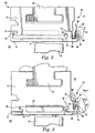
- a shroud segment generally designated 10, comprised of an outer shroud 12 and a pair of inner shrouds 14 for securement to the outer shroud 12.
- the inner shrouds have hooks 16 and 18 adjacent their leading and trailing edges 17 and 19, respectively, for circumferential slidable engagement in grooves 20 and 22 of the outer shroud 12 in final assembly.
- the inner and outer shrouds also mount an impingement cooling plate 24 between the shrouds for impingement cooling of the wall surfaces 26 of the shroud segment, for example, by steam impingement cooling, which forms no part of the present invention.
- the outer shroud 12 has a radially outer dovetail groove 30 for receiving a hook 32 forming part of the fixed turbine shell for securing the shroud segment 10 to the shell. It will be appreciated that an annular array of shroud segments 10 are formed about the rotor of the gas turbine and about the tips of the buckets 35 on the rotor thereby defining an outer wall or boundary 31 for the hot gas flowing along the hot gas path 33 of the turbine.
- a leaf seal assembly is provided along the trailing edge of the shroud segment 10 and interfaces with a forward flange or nub 42 of a leading edge side wall 44 of a nozzle stage outer band 45.
- the seal assembly 40 seals between the hot gas path 33 and a cavity 37 on the turbine shell side.
- the leaf seal 40 is mounted on the outer shroud 12.
- the trailing edge of the outer shroud 12 includes a seat 46, e.g., a groove, having a radially outwardly and circumferentially extending flange 48 for receiving the leaf seal assembly 40.
- the leaf seal assembly 40 includes a circumferentially elongated flat plate 50 received in the groove 46.
- the plate 50 extends radially outwardly and engages along its trailing face the flange 42 of the leading edge side wall 44 of the nozzle band 45.
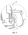
- the leaf seal plate 50 includes a pair of openings 54 ( Figure 1 ) adjacent opposite ends.
- a pair of generally U-shaped spring clips 56 likewise have openings 58 passing therethrough.
- the spring clips 56 have a base and a pair of legs and are disposed in opposite ends of the groove 46 with the openings 58 thereof aligned with openings 54 of the leaf seal plate 50.
- Pins 60 are extended through the plate 50 and spring clips 56 to engage in openings on the trailing edge face of the outer shroud 12 and within the groove 46.
- the pins 60 are preferably tack-welded in place to secure the leaf seal plate 50.
- the plate 50 as illustrated in Figure 4 has a bump or projection 57 along its aft face which lies in contact with the flange 48 at locations between the pins 60 and the outer edges of the spring clips 56.
- the projection 57 serves as a pivot to ensure that the seal lies perpendicular to the centerline of the rotor during operation which, in turn, creates the smallest leakage past the seal.
- one end of the seal plate 50 includes an overlap 66 for sealing between adjacent shroud segments. These overlaps 66 also include "suck down" holes to assure the overlap creates an effective seal.
- the outer and inner shrouds are coupled to one another, with the impingement plate therebetween, using the respective complementary hooks 16, 18 and grooves 20, 22.
- the leaf seal spring clips 56 are then installed in groove 46, followed by the leaf seal plate 50.
- the seal plate is disposed between the flange 48 and the trailing leg of the U-shaped clips 56.
- Pins 60 are then inserted through the aligned openings 54 and 58 and into the outer shroud 12 and tack-welded in place.
- the shroud segment is then circumferentially received on the turbine shell hook 32 and pinned in place.
- stator shroud segment 68 includes an outer shroud 70 having a pair of grooves 72 and 73 along respective leading and trailing edges thereof.
- the inner shroud 74 has a pair of flanges 76 and 78 for engaging in the respective grooves 72 and 73 of the outer shroud 70.
- the leaf seal assembly, generally designated 80 is secured in a seat 82, e.g., a groove, formed along the trailing edge of the inner shrouds 74.
- the seal assembly 80 includes a seal plate 84 and a pair of spring clips 86, the spring clips and seal plate 84 having aligned openings for receiving pins 89 adjacent opposite ends of the groove for securing the seal assembly in the groove 82 of the inner shroud 74.
- a bump 83 is formed along the aft face of the plate 84 and serves as a pivot point such that the plate is perpendicular to the turbine rotor axis for effective sealing engagement against the flange of the leading edge side wall 88 of the nozzle band 90.
Landscapes
- Engineering & Computer Science (AREA)
- General Engineering & Computer Science (AREA)
- Mechanical Engineering (AREA)
- Turbine Rotor Nozzle Sealing (AREA)
Applications Claiming Priority (2)
| Application Number | Priority Date | Filing Date | Title |
|---|---|---|---|
| US09/571,814 US6402466B1 (en) | 2000-05-16 | 2000-05-16 | Leaf seal for gas turbine stator shrouds and a nozzle band |
| US571814 | 2000-05-16 |
Publications (3)
| Publication Number | Publication Date |
|---|---|
| EP1156188A2 EP1156188A2 (en) | 2001-11-21 |
| EP1156188A3 EP1156188A3 (en) | 2003-09-24 |
| EP1156188B1 true EP1156188B1 (en) | 2008-06-11 |
Family
ID=24285177
Family Applications (1)
| Application Number | Title | Priority Date | Filing Date |
|---|---|---|---|
| EP01300367A Expired - Lifetime EP1156188B1 (en) | 2000-05-16 | 2001-01-16 | Gas turbine with a leaf seal for the stator shroud |
Country Status (7)
| Country | Link |
|---|---|
| US (1) | US6402466B1 (enExample) |
| EP (1) | EP1156188B1 (enExample) |
| JP (1) | JP4721524B2 (enExample) |
| KR (1) | KR20010105147A (enExample) |
| AT (1) | ATE398229T1 (enExample) |
| CZ (1) | CZ200143A3 (enExample) |
| DE (1) | DE60134360D1 (enExample) |
Families Citing this family (72)
| Publication number | Priority date | Publication date | Assignee | Title |
|---|---|---|---|---|
| US6464457B1 (en) * | 2001-06-21 | 2002-10-15 | General Electric Company | Turbine leaf seal mounting with headless pins |
| US6752592B2 (en) | 2001-12-28 | 2004-06-22 | General Electric Company | Supplemental seal for the chordal hinge seals in a gas turbine |
| US6659472B2 (en) * | 2001-12-28 | 2003-12-09 | General Electric Company | Seal for gas turbine nozzle and shroud interface |
| US6764081B2 (en) | 2001-12-28 | 2004-07-20 | General Electric Company | Supplemental seal for the chordal hinge seals in a gas turbine and methods of installation |
| JP3840556B2 (ja) * | 2002-08-22 | 2006-11-01 | 川崎重工業株式会社 | 燃焼器ライナのシール構造 |
| US6733234B2 (en) | 2002-09-13 | 2004-05-11 | Siemens Westinghouse Power Corporation | Biased wear resistant turbine seal assembly |
| US6883807B2 (en) | 2002-09-13 | 2005-04-26 | Seimens Westinghouse Power Corporation | Multidirectional turbine shim seal |
| US7093837B2 (en) | 2002-09-26 | 2006-08-22 | Siemens Westinghouse Power Corporation | Turbine spring clip seal |
| US6832892B2 (en) | 2002-12-11 | 2004-12-21 | General Electric Company | Sealing of steam turbine bucket hook leakages using a braided rope seal |
| US6939106B2 (en) * | 2002-12-11 | 2005-09-06 | General Electric Company | Sealing of steam turbine nozzle hook leakages using a braided rope seal |
| US6814538B2 (en) | 2003-01-22 | 2004-11-09 | General Electric Company | Turbine stage one shroud configuration and method for service enhancement |
| DE10306915A1 (de) * | 2003-02-19 | 2004-09-02 | Alstom Technology Ltd | Dichtungsanordnung, insbesondere für Gasturbinen |
| US6869082B2 (en) * | 2003-06-12 | 2005-03-22 | Siemens Westinghouse Power Corporation | Turbine spring clip seal |
| US7086829B2 (en) | 2004-02-03 | 2006-08-08 | General Electric Company | Film cooling for the trailing edge of a steam cooled nozzle |
| CN100404924C (zh) * | 2004-02-25 | 2008-07-23 | J·W·巴克内尔 | 用于液压组件的密封件 |
| FR2868125B1 (fr) * | 2004-03-26 | 2006-07-21 | Snecma Moteurs Sa | Turbomachine comprenant deux sous-ensembles assembles sous contrainte axiale |
| US7217089B2 (en) * | 2005-01-14 | 2007-05-15 | Pratt & Whitney Canada Corp. | Gas turbine engine shroud sealing arrangement |
| US7374395B2 (en) * | 2005-07-19 | 2008-05-20 | Pratt & Whitney Canada Corp. | Turbine shroud segment feather seal located in radial shroud legs |
| US7338253B2 (en) * | 2005-09-15 | 2008-03-04 | General Electric Company | Resilient seal on trailing edge of turbine inner shroud and method for shroud post impingement cavity sealing |
| DE102006017377A1 (de) * | 2006-04-11 | 2007-11-08 | Rolls-Royce Deutschland Ltd & Co Kg | Klappendichtung für eine Strömungsmaschine |
| US7524167B2 (en) * | 2006-05-04 | 2009-04-28 | Siemens Energy, Inc. | Combustor spring clip seal system |
| US7811054B2 (en) * | 2007-05-30 | 2010-10-12 | General Electric Company | Shroud configuration having sloped seal |
| US20090110546A1 (en) * | 2007-10-29 | 2009-04-30 | United Technologies Corp. | Feather Seals and Gas Turbine Engine Systems Involving Such Seals |
| FR2923525B1 (fr) * | 2007-11-13 | 2009-12-18 | Snecma | Etancheite d'un anneau de rotor dans un etage de turbine |
| US8469656B1 (en) | 2008-01-15 | 2013-06-25 | Siemens Energy, Inc. | Airfoil seal system for gas turbine engine |
| US8500394B2 (en) | 2008-02-20 | 2013-08-06 | United Technologies Corporation | Single channel inner diameter shroud with lightweight inner core |
| US8118548B2 (en) * | 2008-09-15 | 2012-02-21 | General Electric Company | Shroud for a turbomachine |
| US20100072710A1 (en) * | 2008-09-22 | 2010-03-25 | General Electric Company | Gas Turbine Seal |
| US8075255B2 (en) * | 2009-03-31 | 2011-12-13 | General Electric Company | Reducing inter-seal gap in gas turbine |
| US20110031704A1 (en) * | 2009-05-15 | 2011-02-10 | Lehr Brian C | Segmented Gaskets |
| FR2949810B1 (fr) * | 2009-09-04 | 2013-06-28 | Turbomeca | Dispositif de support d'un anneau de turbine, turbine avec un tel dispositif et turbomoteur avec une telle turbine |
| US8398090B2 (en) | 2010-06-09 | 2013-03-19 | General Electric Company | Spring loaded seal assembly for turbines |
| US9206904B2 (en) * | 2010-07-08 | 2015-12-08 | Siemens Energy, Inc. | Seal including flexible seal strips |
| EP2508713A1 (en) | 2011-04-04 | 2012-10-10 | Siemens Aktiengesellschaft | Gas turbine comprising a heat shield and method of operation |
| US9115585B2 (en) * | 2011-06-06 | 2015-08-25 | General Electric Company | Seal assembly for gas turbine |
| US9016695B2 (en) * | 2011-08-02 | 2015-04-28 | United Technologies Corporation | Gas turbine exhaust nozzle divergent flap seal |
| US9726043B2 (en) | 2011-12-15 | 2017-08-08 | General Electric Company | Mounting apparatus for low-ductility turbine shroud |
| US9145789B2 (en) * | 2012-09-05 | 2015-09-29 | General Electric Company | Impingement plate for damping and cooling shroud assembly inter segment seals |
| US9416671B2 (en) | 2012-10-04 | 2016-08-16 | General Electric Company | Bimetallic turbine shroud and method of fabricating |
| US9863264B2 (en) * | 2012-12-10 | 2018-01-09 | General Electric Company | Turbine shroud engagement arrangement and method |
| WO2015002673A2 (en) * | 2013-02-20 | 2015-01-08 | United Technologies Corporation | Gas turbine engine seal assembly |
| US10100737B2 (en) | 2013-05-16 | 2018-10-16 | Siemens Energy, Inc. | Impingement cooling arrangement having a snap-in plate |
| CA2912428C (en) | 2013-05-17 | 2018-03-13 | General Electric Company | Cmc shroud support system of a gas turbine |
| US10233776B2 (en) | 2013-05-21 | 2019-03-19 | Siemens Energy, Inc. | Gas turbine ring segment cooling apparatus |
| CA2917765C (en) * | 2013-07-19 | 2020-09-15 | General Electric Company | Turbine nozzle with impingement baffle |
| CA2932612C (en) | 2013-12-12 | 2022-01-18 | General Electric Company | Cmc shroud support system |
| US9856737B2 (en) * | 2014-03-27 | 2018-01-02 | United Technologies Corporation | Blades and blade dampers for gas turbine engines |
| WO2015191185A1 (en) | 2014-06-12 | 2015-12-17 | General Electric Company | Shroud hanger assembly |
| US10465558B2 (en) | 2014-06-12 | 2019-11-05 | General Electric Company | Multi-piece shroud hanger assembly |
| JP6363232B2 (ja) | 2014-06-12 | 2018-07-25 | ゼネラル・エレクトリック・カンパニイ | シュラウドハンガーアセンブリ |
| EP2960439A1 (en) * | 2014-06-26 | 2015-12-30 | Siemens Aktiengesellschaft | Turbomachine with an outer sealing and use of the turbomachine |
| US10161259B2 (en) * | 2014-10-28 | 2018-12-25 | General Electric Company | Flexible film-riding seal |
| US9845696B2 (en) * | 2014-12-15 | 2017-12-19 | Pratt & Whitney Canada Corp. | Turbine shroud sealing architecture |
| US10280777B2 (en) | 2014-12-19 | 2019-05-07 | General Electric Company | System and method including a circumferential seal assembly to facilitate sealing in a turbine |
| KR101584156B1 (ko) | 2014-12-22 | 2016-01-22 | 주식회사 포스코 | 가스 터빈용 씨일 및 이를 구비하는 씨일 조립체 |
| US9874104B2 (en) | 2015-02-27 | 2018-01-23 | General Electric Company | Method and system for a ceramic matrix composite shroud hanger assembly |
| US10260364B2 (en) | 2015-03-09 | 2019-04-16 | United Technologies Corporation | Sliding seal |
| US10202862B2 (en) * | 2015-04-08 | 2019-02-12 | United Technologies Corporation | Sliding seal |
| EP3091188B1 (de) * | 2015-05-08 | 2018-08-01 | MTU Aero Engines GmbH | Strömungsmaschine mit einer dichtungseinrichtung |
| US10393147B2 (en) * | 2015-07-23 | 2019-08-27 | Unison Industries, Llc | Fan casing assemblies and method of mounting a cooler to a fan casing |
| US11473437B2 (en) * | 2015-09-24 | 2022-10-18 | General Electric Company | Turbine snap in spring seal |
| US10036269B2 (en) * | 2015-10-23 | 2018-07-31 | General Electric Company | Leaf seal reach over spring with retention mechanism |
| US10087768B2 (en) * | 2015-12-07 | 2018-10-02 | General Electric Company | Steam turbine rotor seal key member, related assembly and steam turbine |
| US10450883B2 (en) | 2016-10-31 | 2019-10-22 | United Technologies Corporation | W-seal shield for interrupted cavity |
| US10408090B2 (en) | 2016-11-17 | 2019-09-10 | United Technologies Corporation | Gas turbine engine article with panel retained by preloaded compliant member |
| DE102016223867A1 (de) * | 2016-11-30 | 2018-05-30 | MTU Aero Engines AG | Turbomaschinen-Dichtungsanordnung |
| US10934877B2 (en) * | 2018-10-31 | 2021-03-02 | Raytheon Technologies Corporation | CMC laminate pocket BOAS with axial attachment scheme |
| US11008894B2 (en) | 2018-10-31 | 2021-05-18 | Raytheon Technologies Corporation | BOAS spring clip |
| US11136896B2 (en) | 2019-04-24 | 2021-10-05 | Raytheon Technologies Corporation | Rotating leaf spring seal |
| FR3095830B1 (fr) * | 2019-05-10 | 2021-05-07 | Safran Aircraft Engines | Module de turbomachine equipe d’un dispositif de maintien de lamelles d’etancheite |
| CN110284929B (zh) * | 2019-07-19 | 2021-10-22 | 中国航发沈阳发动机研究所 | 一种涡轮机匣封严结构 |
| US11761342B2 (en) * | 2020-10-26 | 2023-09-19 | General Electric Company | Sealing assembly for a gas turbine engine having a leaf seal |
Citations (1)
| Publication number | Priority date | Publication date | Assignee | Title |
|---|---|---|---|---|
| US4126405A (en) * | 1976-12-16 | 1978-11-21 | General Electric Company | Turbine nozzle |
Family Cites Families (20)
| Publication number | Priority date | Publication date | Assignee | Title |
|---|---|---|---|---|
| US4184689A (en) * | 1978-10-02 | 1980-01-22 | United Technologies Corporation | Seal structure for an axial flow rotary machine |
| US4314793A (en) * | 1978-12-20 | 1982-02-09 | United Technologies Corporation | Temperature actuated turbine seal |
| FR2649463B1 (fr) * | 1989-07-10 | 1995-01-20 | Gen Electric | Dispositif d'etancheite a feuille |
| US5118120A (en) * | 1989-07-10 | 1992-06-02 | General Electric Company | Leaf seals |
| GB2239678B (en) * | 1989-12-08 | 1993-03-03 | Rolls Royce Plc | Gas turbine engine blade shroud assembly |
| US5211407A (en) * | 1992-04-30 | 1993-05-18 | General Electric Company | Compressor rotor cross shank leak seal for axial dovetails |
| GB9210642D0 (en) * | 1992-05-19 | 1992-07-08 | Rolls Royce Plc | Rotor shroud assembly |
| US5333992A (en) * | 1993-02-05 | 1994-08-02 | United Technologies Corporation | Coolable outer air seal assembly for a gas turbine engine |
| FR2728016B1 (fr) * | 1994-12-07 | 1997-01-17 | Snecma | Distributeur monobloc non-sectorise d'un stator de turbine de turbomachine |
| US5562408A (en) * | 1995-06-06 | 1996-10-08 | General Electric Company | Isolated turbine shroud |
| US5639210A (en) * | 1995-10-23 | 1997-06-17 | United Technologies Corporation | Rotor blade outer tip seal apparatus |
| GB9612441D0 (en) * | 1996-06-14 | 1996-08-14 | Guest John D | Improvements in or relating to tube coupling bodies |
| US5797723A (en) * | 1996-11-13 | 1998-08-25 | General Electric Company | Turbine flowpath seal |
| US6076835A (en) * | 1997-05-21 | 2000-06-20 | Allison Advanced Development Company | Interstage van seal apparatus |
| JPH1162509A (ja) * | 1997-08-18 | 1999-03-05 | Ishikawajima Harima Heavy Ind Co Ltd | ジェットエンジンのタービンシュラウド支持構造 |
| US5971703A (en) * | 1997-12-05 | 1999-10-26 | Pratt & Whitney Canada Inc. | Seal assembly for a gas turbine engine |
| JPH11343809A (ja) * | 1998-06-02 | 1999-12-14 | Ishikawajima Harima Heavy Ind Co Ltd | ガスタービンのタービンシュラウド部のシール構造 |
| FR2780443B1 (fr) * | 1998-06-25 | 2000-08-04 | Snecma | Anneau de stator de turbine haute pression d'une turbomachine |
| US6126389A (en) * | 1998-09-02 | 2000-10-03 | General Electric Co. | Impingement cooling for the shroud of a gas turbine |
| US6164656A (en) * | 1999-01-29 | 2000-12-26 | General Electric Company | Turbine nozzle interface seal and methods |
-
2000
- 2000-05-16 US US09/571,814 patent/US6402466B1/en not_active Expired - Lifetime
-
2001
- 2001-01-04 CZ CZ200143A patent/CZ200143A3/cs unknown
- 2001-01-12 KR KR1020010001724A patent/KR20010105147A/ko not_active Withdrawn
- 2001-01-15 JP JP2001005839A patent/JP4721524B2/ja not_active Expired - Fee Related
- 2001-01-16 DE DE60134360T patent/DE60134360D1/de not_active Expired - Lifetime
- 2001-01-16 AT AT01300367T patent/ATE398229T1/de not_active IP Right Cessation
- 2001-01-16 EP EP01300367A patent/EP1156188B1/en not_active Expired - Lifetime
Patent Citations (1)
| Publication number | Priority date | Publication date | Assignee | Title |
|---|---|---|---|---|
| US4126405A (en) * | 1976-12-16 | 1978-11-21 | General Electric Company | Turbine nozzle |
Also Published As
| Publication number | Publication date |
|---|---|
| EP1156188A3 (en) | 2003-09-24 |
| JP4721524B2 (ja) | 2011-07-13 |
| ATE398229T1 (de) | 2008-07-15 |
| EP1156188A2 (en) | 2001-11-21 |
| DE60134360D1 (de) | 2008-07-24 |
| KR20010105147A (ko) | 2001-11-28 |
| CZ200143A3 (cs) | 2002-01-16 |
| JP2001323804A (ja) | 2001-11-22 |
| US6402466B1 (en) | 2002-06-11 |
Similar Documents
| Publication | Publication Date | Title |
|---|---|---|
| EP1156188B1 (en) | Gas turbine with a leaf seal for the stator shroud | |
| KR100681560B1 (ko) | 가스 터빈 | |
| KR100762536B1 (ko) | 가스 터빈 | |
| US9506374B2 (en) | Component of a turbine with leaf seals and method for sealing against leakage between a vane and a carrier element | |
| JP4130581B2 (ja) | ガスタービンにおける弦ヒンジシールのための補助シール | |
| JP5154788B2 (ja) | シール組立体及びタービンノズル組立体 | |
| EP1340885A2 (en) | Leaf seal support for a gas turbine engine nozzle vane | |
| US20070014668A1 (en) | Seal and locking plate for turbine rotor assembly between turbine blade and turbine vane | |
| JPH05187259A (ja) | タービンノズル支持体 | |
| JP2017082777A (ja) | タービンのスロット付きの弧状リーフシール | |
| JP2007513281A (ja) | 燃焼器壁とノズルプラットフォームとの間の褶動ジョイント | |
| JP2015094360A (ja) | シーリング接続を提供する可撓性の構成部材 | |
| JP6669484B2 (ja) | ガスタービンにおける流路境界及びロータ組立体 | |
| KR20160064018A (ko) | 제 1 스테이지 터빈 베인 장치 | |
| JPH0627483B2 (ja) | 軸流型ガスタービンエンジンのステータ構造体 | |
| KR100767866B1 (ko) | 가스 터빈 | |
| US8888445B2 (en) | Turbomachine seal assembly | |
| US6637753B2 (en) | Supplemental seal for the chordal hinge seals in a gas turbine | |
| KR100747837B1 (ko) | 터빈 및 가스 터빈 | |
| JPH0749832B2 (ja) | ターボ機関 | |
| JP4498695B2 (ja) | タービンノズルロックための方法及び装置 | |
| CN113167126B (zh) | 非接触密封组件中的副密封 | |
| CN112689700B (zh) | 具有防旋转特征的非接触式密封件 | |
| US11519286B2 (en) | Sealing assembly and sealing member therefor with spline seal retention |
Legal Events
| Date | Code | Title | Description |
|---|---|---|---|
| PUAI | Public reference made under article 153(3) epc to a published international application that has entered the european phase |
Free format text: ORIGINAL CODE: 0009012 |
|
| AK | Designated contracting states |
Kind code of ref document: A2 Designated state(s): AT BE CH CY DE DK ES FI FR GB GR IE IT LI LU MC NL PT SE TR |
|
| AX | Request for extension of the european patent |
Free format text: AL;LT;LV;MK;RO;SI |
|
| PUAL | Search report despatched |
Free format text: ORIGINAL CODE: 0009013 |
|
| AK | Designated contracting states |
Kind code of ref document: A3 Designated state(s): AT BE CH CY DE DK ES FI FR GB GR IE IT LI LU MC NL PT SE TR |
|
| AX | Request for extension of the european patent |
Extension state: AL LT LV MK RO SI |
|
| 17P | Request for examination filed |
Effective date: 20040324 |
|
| AKX | Designation fees paid |
Designated state(s): AT BE CH CY DE DK ES FI FR GB GR IE IT LI LU MC NL PT SE TR |
|
| 17Q | First examination report despatched |
Effective date: 20040728 |
|
| GRAP | Despatch of communication of intention to grant a patent |
Free format text: ORIGINAL CODE: EPIDOSNIGR1 |
|
| RTI1 | Title (correction) |
Free format text: GAS TURBINE WITH A LEAF SEAL FOR THE STATOR SHROUD |
|
| GRAS | Grant fee paid |
Free format text: ORIGINAL CODE: EPIDOSNIGR3 |
|
| GRAA | (expected) grant |
Free format text: ORIGINAL CODE: 0009210 |
|
| AK | Designated contracting states |
Kind code of ref document: B1 Designated state(s): AT BE CH CY DE DK ES FI FR GB GR IE IT LI LU MC NL PT SE TR |
|
| REG | Reference to a national code |
Ref country code: GB Ref legal event code: FG4D |
|
| REG | Reference to a national code |
Ref country code: CH Ref legal event code: EP |
|
| REF | Corresponds to: |
Ref document number: 60134360 Country of ref document: DE Date of ref document: 20080724 Kind code of ref document: P |
|
| REG | Reference to a national code |
Ref country code: IE Ref legal event code: FG4D |
|
| PG25 | Lapsed in a contracting state [announced via postgrant information from national office to epo] |
Ref country code: FI Free format text: LAPSE BECAUSE OF FAILURE TO SUBMIT A TRANSLATION OF THE DESCRIPTION OR TO PAY THE FEE WITHIN THE PRESCRIBED TIME-LIMIT Effective date: 20080611 |
|
| PG25 | Lapsed in a contracting state [announced via postgrant information from national office to epo] |
Ref country code: AT Free format text: LAPSE BECAUSE OF FAILURE TO SUBMIT A TRANSLATION OF THE DESCRIPTION OR TO PAY THE FEE WITHIN THE PRESCRIBED TIME-LIMIT Effective date: 20080611 Ref country code: NL Free format text: LAPSE BECAUSE OF FAILURE TO SUBMIT A TRANSLATION OF THE DESCRIPTION OR TO PAY THE FEE WITHIN THE PRESCRIBED TIME-LIMIT Effective date: 20080611 |
|
| NLV1 | Nl: lapsed or annulled due to failure to fulfill the requirements of art. 29p and 29m of the patents act | ||
| PG25 | Lapsed in a contracting state [announced via postgrant information from national office to epo] |
Ref country code: SE Free format text: LAPSE BECAUSE OF FAILURE TO SUBMIT A TRANSLATION OF THE DESCRIPTION OR TO PAY THE FEE WITHIN THE PRESCRIBED TIME-LIMIT Effective date: 20080911 Ref country code: PT Free format text: LAPSE BECAUSE OF FAILURE TO SUBMIT A TRANSLATION OF THE DESCRIPTION OR TO PAY THE FEE WITHIN THE PRESCRIBED TIME-LIMIT Effective date: 20081111 Ref country code: ES Free format text: LAPSE BECAUSE OF FAILURE TO SUBMIT A TRANSLATION OF THE DESCRIPTION OR TO PAY THE FEE WITHIN THE PRESCRIBED TIME-LIMIT Effective date: 20080922 |
|
| PG25 | Lapsed in a contracting state [announced via postgrant information from national office to epo] |
Ref country code: BE Free format text: LAPSE BECAUSE OF FAILURE TO SUBMIT A TRANSLATION OF THE DESCRIPTION OR TO PAY THE FEE WITHIN THE PRESCRIBED TIME-LIMIT Effective date: 20080611 |
|
| PLBE | No opposition filed within time limit |
Free format text: ORIGINAL CODE: 0009261 |
|
| STAA | Information on the status of an ep patent application or granted ep patent |
Free format text: STATUS: NO OPPOSITION FILED WITHIN TIME LIMIT |
|
| PG25 | Lapsed in a contracting state [announced via postgrant information from national office to epo] |
Ref country code: DK Free format text: LAPSE BECAUSE OF FAILURE TO SUBMIT A TRANSLATION OF THE DESCRIPTION OR TO PAY THE FEE WITHIN THE PRESCRIBED TIME-LIMIT Effective date: 20080611 |
|
| 26N | No opposition filed |
Effective date: 20090312 |
|
| PG25 | Lapsed in a contracting state [announced via postgrant information from national office to epo] |
Ref country code: MC Free format text: LAPSE BECAUSE OF NON-PAYMENT OF DUE FEES Effective date: 20090131 |
|
| REG | Reference to a national code |
Ref country code: CH Ref legal event code: PL |
|
| PG25 | Lapsed in a contracting state [announced via postgrant information from national office to epo] |
Ref country code: LI Free format text: LAPSE BECAUSE OF NON-PAYMENT OF DUE FEES Effective date: 20090131 Ref country code: CH Free format text: LAPSE BECAUSE OF NON-PAYMENT OF DUE FEES Effective date: 20090131 |
|
| PG25 | Lapsed in a contracting state [announced via postgrant information from national office to epo] |
Ref country code: IE Free format text: LAPSE BECAUSE OF NON-PAYMENT OF DUE FEES Effective date: 20090116 |
|
| PG25 | Lapsed in a contracting state [announced via postgrant information from national office to epo] |
Ref country code: GR Free format text: LAPSE BECAUSE OF FAILURE TO SUBMIT A TRANSLATION OF THE DESCRIPTION OR TO PAY THE FEE WITHIN THE PRESCRIBED TIME-LIMIT Effective date: 20080912 |
|
| PG25 | Lapsed in a contracting state [announced via postgrant information from national office to epo] |
Ref country code: LU Free format text: LAPSE BECAUSE OF NON-PAYMENT OF DUE FEES Effective date: 20090116 |
|
| PG25 | Lapsed in a contracting state [announced via postgrant information from national office to epo] |
Ref country code: TR Free format text: LAPSE BECAUSE OF FAILURE TO SUBMIT A TRANSLATION OF THE DESCRIPTION OR TO PAY THE FEE WITHIN THE PRESCRIBED TIME-LIMIT Effective date: 20080611 |
|
| PG25 | Lapsed in a contracting state [announced via postgrant information from national office to epo] |
Ref country code: CY Free format text: LAPSE BECAUSE OF FAILURE TO SUBMIT A TRANSLATION OF THE DESCRIPTION OR TO PAY THE FEE WITHIN THE PRESCRIBED TIME-LIMIT Effective date: 20080611 |
|
| REG | Reference to a national code |
Ref country code: FR Ref legal event code: PLFP Year of fee payment: 16 |
|
| PGFP | Annual fee paid to national office [announced via postgrant information from national office to epo] |
Ref country code: FR Payment date: 20160126 Year of fee payment: 16 Ref country code: GB Payment date: 20160127 Year of fee payment: 16 |
|
| GBPC | Gb: european patent ceased through non-payment of renewal fee |
Effective date: 20170116 |
|
| REG | Reference to a national code |
Ref country code: FR Ref legal event code: ST Effective date: 20170929 |
|
| PG25 | Lapsed in a contracting state [announced via postgrant information from national office to epo] |
Ref country code: FR Free format text: LAPSE BECAUSE OF NON-PAYMENT OF DUE FEES Effective date: 20170131 |
|
| PG25 | Lapsed in a contracting state [announced via postgrant information from national office to epo] |
Ref country code: GB Free format text: LAPSE BECAUSE OF NON-PAYMENT OF DUE FEES Effective date: 20170116 |
|
| PGFP | Annual fee paid to national office [announced via postgrant information from national office to epo] |
Ref country code: IT Payment date: 20190102 Year of fee payment: 19 Ref country code: DE Payment date: 20181218 Year of fee payment: 19 |
|
| REG | Reference to a national code |
Ref country code: DE Ref legal event code: R119 Ref document number: 60134360 Country of ref document: DE |
|
| PG25 | Lapsed in a contracting state [announced via postgrant information from national office to epo] |
Ref country code: DE Free format text: LAPSE BECAUSE OF NON-PAYMENT OF DUE FEES Effective date: 20200801 |
|
| PG25 | Lapsed in a contracting state [announced via postgrant information from national office to epo] |
Ref country code: IT Free format text: LAPSE BECAUSE OF NON-PAYMENT OF DUE FEES Effective date: 20200116 |