EP1154550A1 - Egr valve device - Google Patents
Egr valve device Download PDFInfo
- Publication number
- EP1154550A1 EP1154550A1 EP99974199A EP99974199A EP1154550A1 EP 1154550 A1 EP1154550 A1 EP 1154550A1 EP 99974199 A EP99974199 A EP 99974199A EP 99974199 A EP99974199 A EP 99974199A EP 1154550 A1 EP1154550 A1 EP 1154550A1
- Authority
- EP
- European Patent Office
- Prior art keywords
- rotor
- current carrying
- bearing
- carrying device
- motor
- Prior art date
- Legal status (The legal status is an assumption and is not a legal conclusion. Google has not performed a legal analysis and makes no representation as to the accuracy of the status listed.)
- Granted
Links
Images


Classifications
-
- H—ELECTRICITY
- H02—GENERATION; CONVERSION OR DISTRIBUTION OF ELECTRIC POWER
- H02K—DYNAMO-ELECTRIC MACHINES
- H02K21/00—Synchronous motors having permanent magnets; Synchronous generators having permanent magnets
- H02K21/12—Synchronous motors having permanent magnets; Synchronous generators having permanent magnets with stationary armatures and rotating magnets
- H02K21/14—Synchronous motors having permanent magnets; Synchronous generators having permanent magnets with stationary armatures and rotating magnets with magnets rotating within the armatures
-
- H—ELECTRICITY
- H02—GENERATION; CONVERSION OR DISTRIBUTION OF ELECTRIC POWER
- H02K—DYNAMO-ELECTRIC MACHINES
- H02K7/00—Arrangements for handling mechanical energy structurally associated with dynamo-electric machines, e.g. structural association with mechanical driving motors or auxiliary dynamo-electric machines
- H02K7/06—Means for converting reciprocating motion into rotary motion or vice versa
-
- F—MECHANICAL ENGINEERING; LIGHTING; HEATING; WEAPONS; BLASTING
- F02—COMBUSTION ENGINES; HOT-GAS OR COMBUSTION-PRODUCT ENGINE PLANTS
- F02M—SUPPLYING COMBUSTION ENGINES IN GENERAL WITH COMBUSTIBLE MIXTURES OR CONSTITUENTS THEREOF
- F02M26/00—Engine-pertinent apparatus for adding exhaust gases to combustion-air, main fuel or fuel-air mixture, e.g. by exhaust gas recirculation [EGR] systems
- F02M26/52—Systems for actuating EGR valves
- F02M26/53—Systems for actuating EGR valves using electric actuators, e.g. solenoids
- F02M26/54—Rotary actuators, e.g. step motors
-
- H—ELECTRICITY
- H02—GENERATION; CONVERSION OR DISTRIBUTION OF ELECTRIC POWER
- H02K—DYNAMO-ELECTRIC MACHINES
- H02K23/00—DC commutator motors or generators having mechanical commutator; Universal AC/DC commutator motors
- H02K23/62—Motors or generators with stationary armatures and rotating excitation field
-
- F—MECHANICAL ENGINEERING; LIGHTING; HEATING; WEAPONS; BLASTING
- F02—COMBUSTION ENGINES; HOT-GAS OR COMBUSTION-PRODUCT ENGINE PLANTS
- F02M—SUPPLYING COMBUSTION ENGINES IN GENERAL WITH COMBUSTIBLE MIXTURES OR CONSTITUENTS THEREOF
- F02M26/00—Engine-pertinent apparatus for adding exhaust gases to combustion-air, main fuel or fuel-air mixture, e.g. by exhaust gas recirculation [EGR] systems
- F02M26/45—Sensors specially adapted for EGR systems
- F02M26/48—EGR valve position sensors
-
- F—MECHANICAL ENGINEERING; LIGHTING; HEATING; WEAPONS; BLASTING
- F02—COMBUSTION ENGINES; HOT-GAS OR COMBUSTION-PRODUCT ENGINE PLANTS
- F02M—SUPPLYING COMBUSTION ENGINES IN GENERAL WITH COMBUSTIBLE MIXTURES OR CONSTITUENTS THEREOF
- F02M26/00—Engine-pertinent apparatus for adding exhaust gases to combustion-air, main fuel or fuel-air mixture, e.g. by exhaust gas recirculation [EGR] systems
- F02M26/65—Constructional details of EGR valves
- F02M26/66—Lift valves, e.g. poppet valves
- F02M26/67—Pintles; Spindles; Springs; Bearings; Sealings; Connections to actuators
Definitions
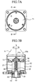
- 27 denotes a bearing which supports a lower end of the rotor 21.
- 28 denotes a commutator which is integrally fitted to an upper end of the rotor 21.
- the motor brush 30 and the commutator 28 are arranged at a position on an upper end of the rotor 21 and below the bearing which supports an upper end of the rotor 21 which is composed of the rotor shaft 26 and the slide ball 25.
- the EGR valve device as defined by the present invention is provided with a shielding member which shields an opening between the motor rotating unit and the current carrying device.
- the EGR valve device as defined by the present invention is provided with the shielding member which is tightly fitted to an outer peripheral face of an outer ring of a bearing in which an inner peripheral face of an inner ring is tightly fitted to an outer peripheral face of the extension of the rotor to which the magnets are fitted.
- the shielding member seals the bearing, covers an open face of the motor rotating unit of the current carrying device and is arranged between the bearing and the current carrying device.
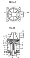
- reference numeral 51 denotes a sensor unit provided with a power supply terminal and a position sensor (not shown) for detecting the aperture of a valve
- 52 denotes a mantle member of a valve driving unit which has a direct current (DC) motor in an inner space.
- the DC motor acts as a torque generation source for opening and closing the valve.
- 53 denotes each of a plurality of stator cores.
- 54 denotes each of a plurality of coils comprising a stator.
- the coils 54 are arranged at approximately equal intervals on the periphery of the series of stator cores 53.
- rotor 55 denotes a rotor with a hollow space forming a threaded portion 56 on an internal face and which has a plurality of magnets 57 on an outer periphery.
- a fixed gap is formed between the outer peripheral face of the magnets 57 and the inner peripheral face of the stator core 53.
Landscapes
- Engineering & Computer Science (AREA)
- Power Engineering (AREA)
- Chemical & Material Sciences (AREA)
- Combustion & Propulsion (AREA)
- Mechanical Engineering (AREA)
- General Engineering & Computer Science (AREA)
- Connection Of Motors, Electrical Generators, Mechanical Devices, And The Like (AREA)
- Exhaust-Gas Circulating Devices (AREA)
- Electrically Driven Valve-Operating Means (AREA)
Abstract
Description
Claims (5)
- An EGR valve device comprising:a motor rotating unit having a stator, in which each of a fixed number of coils is arranged in a peripheral direction of a stator core, and a rotor in which each of a plurality of magnets is fitted to an outer peripheral face corresponding to one coil of the stator;a valve drive mechanism for driving a valve linearly according to the rotation of the rotor of the motor rotating unit;a bearing for rotatably supporting the rotor, to which the magnets are fitted, with respect to the stator; anda current carrying device, which is arranged at a position placed on an outer side opposite to a side arranging the magnets on a rotational axis of the rotor with respect to the bearing, for commutating a direct current supplied from a power source according to a position of the rotor and supplying the commutated current to one coil of the stator.
- An EGR valve device according to claim 1, wherein the current carrying device comprises a plurality of slip rings, a plurality of commutator pieces and a plurality of motor brushes, a disk-shaped feeding unit comprises the slip rings and the commutator pieces, and the disk-shaped feeding unit is integrally fitted to an extension of the rotor which extends to the outer side opposite to the side arranging the magnets on the rotational axis of the rotor with respect to the bearing.
- An EGR valve device according to claim 2, further comprising a shielding member which shields an opening between the motor rotating unit and the current carrying device.
- An EGR valve device according to claim 3, wherein the shielding member is tightly fitted to an outer peripheral face of an outer ring of a bearing in which an inner peripheral face of an inner ring is tightly fitted to an outer peripheral face of the extension of the rotor on which the magnets are fitted, and the shielding member seals the bearing, covers an open face of the motor rotating unit placed toward the current carrying device and is arranged between the bearing and the current carrying device.
- An EGR valve device according to claim 1, wherein the current carrying device is assembled onto the position of the extension of the rotor after assembling the motor rotating unit.
Applications Claiming Priority (1)
| Application Number | Priority Date | Filing Date | Title |
|---|---|---|---|
| PCT/JP1999/006456 WO2001037409A1 (en) | 1999-11-18 | 1999-11-18 | Egr valve device |
Publications (3)
| Publication Number | Publication Date |
|---|---|
| EP1154550A1 true EP1154550A1 (en) | 2001-11-14 |
| EP1154550A4 EP1154550A4 (en) | 2002-10-02 |
| EP1154550B1 EP1154550B1 (en) | 2010-11-17 |
Family
ID=14237329
Family Applications (1)
| Application Number | Title | Priority Date | Filing Date |
|---|---|---|---|
| EP99974199A Expired - Lifetime EP1154550B1 (en) | 1999-11-18 | 1999-11-18 | Egr valve device |
Country Status (6)
| Country | Link |
|---|---|
| US (1) | US6412753B2 (en) |
| EP (1) | EP1154550B1 (en) |
| KR (1) | KR100586782B1 (en) |
| CN (1) | CN1182644C (en) |
| DE (1) | DE69942952D1 (en) |
| WO (1) | WO2001037409A1 (en) |
Families Citing this family (17)
| Publication number | Priority date | Publication date | Assignee | Title |
|---|---|---|---|---|
| JP3683530B2 (en) * | 1999-11-18 | 2005-08-17 | 三菱電機株式会社 | Energizing device for EGR valve device |
| DE10295970T5 (en) | 2001-08-31 | 2004-04-22 | Mitsubishi Denki K.K. | engine |
| KR20030052034A (en) * | 2001-12-20 | 2003-06-26 | 현대자동차주식회사 | Egr apparatus for hybrid vehicles |
| US20030140907A1 (en) * | 2002-01-31 | 2003-07-31 | Frederic Gagnon | Flexible circuit connection for moving coil of an automotive emission control valve |
| JP4531359B2 (en) * | 2003-07-18 | 2010-08-25 | 三菱電機株式会社 | motor |
| JP2005117822A (en) * | 2003-10-09 | 2005-04-28 | Aisin Seiki Co Ltd | DC motor and power supply method thereof |
| DE202004012027U1 (en) * | 2004-07-31 | 2004-09-23 | Alcatel | Small electric motor |
| ES2233217B1 (en) * | 2005-02-08 | 2007-03-16 | Dayco Ensa, S.L. | BY-PASS VALVE. |
| JP4920486B2 (en) * | 2007-05-02 | 2012-04-18 | 三菱電機株式会社 | EGR valve device |
| DE112008003498B4 (en) * | 2007-12-27 | 2015-07-02 | Mitsubishi Electric Corp. | valve device |
| JP5179892B2 (en) * | 2008-02-01 | 2013-04-10 | 三菱電機株式会社 | Energizing device for rotating electrical machines |
| CN102076949B (en) * | 2008-08-01 | 2013-06-05 | 三菱电机株式会社 | Valve control apparatus and valve apparatus |
| JP5270735B2 (en) * | 2011-09-13 | 2013-08-21 | トヨタ自動車株式会社 | Rotating electric machine and power transmission device |
| US8974201B2 (en) | 2012-02-23 | 2015-03-10 | Ge Oil & Gas Compression Systems, Llc | Rotating compressor valve |
| CN102635467A (en) * | 2012-03-30 | 2012-08-15 | 常州市美特精密电机有限公司 | Automobile exhaust gas recycling circulating valve |
| US9266702B2 (en) | 2012-06-29 | 2016-02-23 | Warn Industries, Inc. | Winch |
| KR101629602B1 (en) * | 2015-01-08 | 2016-06-10 | 효성전기주식회사 | 6 magnet and 13 core slot with the motor for exhaust gas recirculation device |
Family Cites Families (9)
| Publication number | Priority date | Publication date | Assignee | Title |
|---|---|---|---|---|
| US2465224A (en) * | 1945-10-13 | 1949-03-22 | Hansen Mfg Company Inc | Electric motor |
| DE2836977C2 (en) * | 1978-08-24 | 1984-09-20 | Wüstholz KG, 7209 Aldingen | DC machine |
| JPS5981271A (en) | 1982-10-30 | 1984-05-10 | Mazda Motor Corp | 4-wheel steering device of vehicle |
| JPS5981271U (en) * | 1982-11-24 | 1984-06-01 | 長田電機工業株式会社 | Electric motor |
| JP2978677B2 (en) * | 1993-07-07 | 1999-11-15 | 三菱電機エンジニアリング株式会社 | Electric control valve device |
| JPH10220620A (en) | 1997-02-07 | 1998-08-21 | Unisia Jecs Corp | Control device for EGR valve |
| JPH11132110A (en) * | 1997-10-28 | 1999-05-18 | Unisia Jecs Corp | Control device for EGR valve |
| JPH11159405A (en) * | 1997-11-27 | 1999-06-15 | Unisia Jecs Corp | Control device for EGR valve |
| JPH11270415A (en) * | 1998-03-25 | 1999-10-05 | Unisia Jecs Corp | EGR valve |
-
1999
- 1999-11-18 CN CNB998156477A patent/CN1182644C/en not_active Expired - Lifetime
- 1999-11-18 DE DE69942952T patent/DE69942952D1/en not_active Expired - Lifetime
- 1999-11-18 EP EP99974199A patent/EP1154550B1/en not_active Expired - Lifetime
- 1999-11-18 WO PCT/JP1999/006456 patent/WO2001037409A1/en not_active Ceased
- 1999-11-18 KR KR1020017008533A patent/KR100586782B1/en not_active Expired - Lifetime
-
2001
- 2001-07-16 US US09/905,076 patent/US6412753B2/en not_active Expired - Lifetime
Also Published As
| Publication number | Publication date |
|---|---|
| DE69942952D1 (en) | 2010-12-30 |
| WO2001037409A1 (en) | 2001-05-25 |
| EP1154550A4 (en) | 2002-10-02 |
| KR20010108065A (en) | 2001-12-07 |
| EP1154550B1 (en) | 2010-11-17 |
| CN1333942A (en) | 2002-01-30 |
| CN1182644C (en) | 2004-12-29 |
| US6412753B2 (en) | 2002-07-02 |
| US20010050346A1 (en) | 2001-12-13 |
| KR100586782B1 (en) | 2006-06-08 |
Similar Documents
| Publication | Publication Date | Title |
|---|---|---|
| EP1154550A1 (en) | Egr valve device | |
| US8004134B2 (en) | Electric motor, rotary actuator and rotary apparatus | |
| KR101566614B1 (en) | Exhaust system for internal combustion engine | |
| US6888277B2 (en) | Electro drive | |
| US8723381B2 (en) | Electric motor | |
| EP1729400B1 (en) | Motor | |
| JPH0956091A (en) | Permanent magnet type rotating electric machine | |
| US11355990B2 (en) | Drive device | |
| US20230208251A1 (en) | Electric motor | |
| US20040051404A1 (en) | Stepping motor | |
| EP1113569B1 (en) | Device for energizing dc motor and valve device comprising device for energizing dc motor | |
| US6488259B1 (en) | Valve device | |
| US12379020B2 (en) | Electric actuator | |
| US20250158479A1 (en) | Electric motor, in particular radiator fan motor | |
| JP4920486B2 (en) | EGR valve device | |
| US6681799B2 (en) | Exhaust gas regulator including an overmolded housing | |
| JPWO2001037409A1 (en) | EGR valve device | |
| CN101595624A (en) | DC motor | |
| EP3453916B1 (en) | Speed reducer-attached motor | |
| US20250088063A1 (en) | Rotating electric machine | |
| WO2022201173A1 (en) | An electrical machine | |
| CN117955283A (en) | Motor with a motor housing having a motor housing with a motor housing | |
| US20200366041A1 (en) | Dc motor brush holder assembly |
Legal Events
| Date | Code | Title | Description |
|---|---|---|---|
| PUAI | Public reference made under article 153(3) epc to a published international application that has entered the european phase |
Free format text: ORIGINAL CODE: 0009012 |
|
| 17P | Request for examination filed |
Effective date: 20010703 |
|
| AK | Designated contracting states |
Kind code of ref document: A1 Designated state(s): AT BE CH CY DE DK ES FI FR GB GR IE IT LI LU MC NL PT SE |
|
| A4 | Supplementary search report drawn up and despatched |
Effective date: 20020821 |
|
| AK | Designated contracting states |
Kind code of ref document: A4 Designated state(s): AT BE CH CY DE DK ES FI FR GB GR IE IT LI LU MC NL PT SE |
|
| RBV | Designated contracting states (corrected) |
Designated state(s): DE FR GB IT |
|
| RAP1 | Party data changed (applicant data changed or rights of an application transferred) |
Owner name: MITSUBISHI DENKI KABUSHIKI KAISHA |
|
| 17Q | First examination report despatched |
Effective date: 20061025 |
|
| GRAP | Despatch of communication of intention to grant a patent |
Free format text: ORIGINAL CODE: EPIDOSNIGR1 |
|
| GRAS | Grant fee paid |
Free format text: ORIGINAL CODE: EPIDOSNIGR3 |
|
| GRAA | (expected) grant |
Free format text: ORIGINAL CODE: 0009210 |
|
| AK | Designated contracting states |
Kind code of ref document: B1 Designated state(s): DE FR GB IT |
|
| REG | Reference to a national code |
Ref country code: GB Ref legal event code: FG4D |
|
| REF | Corresponds to: |
Ref document number: 69942952 Country of ref document: DE Date of ref document: 20101230 Kind code of ref document: P |
|
| PLBE | No opposition filed within time limit |
Free format text: ORIGINAL CODE: 0009261 |
|
| STAA | Information on the status of an ep patent application or granted ep patent |
Free format text: STATUS: NO OPPOSITION FILED WITHIN TIME LIMIT |
|
| 26N | No opposition filed |
Effective date: 20110818 |
|
| GBPC | Gb: european patent ceased through non-payment of renewal fee |
Effective date: 20110217 |
|
| REG | Reference to a national code |
Ref country code: DE Ref legal event code: R097 Ref document number: 69942952 Country of ref document: DE Effective date: 20110818 |
|
| PG25 | Lapsed in a contracting state [announced via postgrant information from national office to epo] |
Ref country code: IT Free format text: LAPSE BECAUSE OF FAILURE TO SUBMIT A TRANSLATION OF THE DESCRIPTION OR TO PAY THE FEE WITHIN THE PRESCRIBED TIME-LIMIT Effective date: 20101117 |
|
| REG | Reference to a national code |
Ref country code: FR Ref legal event code: ST Effective date: 20111125 |
|
| PG25 | Lapsed in a contracting state [announced via postgrant information from national office to epo] |
Ref country code: FR Free format text: LAPSE BECAUSE OF NON-PAYMENT OF DUE FEES Effective date: 20110117 |
|
| PG25 | Lapsed in a contracting state [announced via postgrant information from national office to epo] |
Ref country code: GB Free format text: LAPSE BECAUSE OF NON-PAYMENT OF DUE FEES Effective date: 20110217 |
|
| REG | Reference to a national code |
Ref country code: DE Ref legal event code: R084 Ref document number: 69942952 Country of ref document: DE Effective date: 20130503 |
|
| PGFP | Annual fee paid to national office [announced via postgrant information from national office to epo] |
Ref country code: DE Payment date: 20181106 Year of fee payment: 20 |
|
| REG | Reference to a national code |
Ref country code: DE Ref legal event code: R071 Ref document number: 69942952 Country of ref document: DE |