EP1154455A2 - Method and apparatus for cleaning translucent tube for discharge lamp, and discharge lamp - Google Patents
Method and apparatus for cleaning translucent tube for discharge lamp, and discharge lamp Download PDFInfo
- Publication number
- EP1154455A2 EP1154455A2 EP01111047A EP01111047A EP1154455A2 EP 1154455 A2 EP1154455 A2 EP 1154455A2 EP 01111047 A EP01111047 A EP 01111047A EP 01111047 A EP01111047 A EP 01111047A EP 1154455 A2 EP1154455 A2 EP 1154455A2
- Authority
- EP
- European Patent Office
- Prior art keywords
- cleaning
- discharge lamp
- tube
- cleaning liquid
- translucent tube
- Prior art date
- Legal status (The legal status is an assumption and is not a legal conclusion. Google has not performed a legal analysis and makes no representation as to the accuracy of the status listed.)
- Withdrawn
Links
Images





Classifications
-
- H—ELECTRICITY
- H01—ELECTRIC ELEMENTS
- H01J—ELECTRIC DISCHARGE TUBES OR DISCHARGE LAMPS
- H01J9/00—Apparatus or processes specially adapted for the manufacture, installation, removal, maintenance of electric discharge tubes, discharge lamps, or parts thereof; Recovery of material from discharge tubes or lamps
- H01J9/38—Exhausting, degassing, filling, or cleaning vessels
-
- H—ELECTRICITY
- H01—ELECTRIC ELEMENTS
- H01J—ELECTRIC DISCHARGE TUBES OR DISCHARGE LAMPS
- H01J61/00—Gas-discharge or vapour-discharge lamps
- H01J61/02—Details
- H01J61/30—Vessels; Containers
Definitions
- the present invention relates to a method and an apparatus for cleaning a translucent tube for a discharge lamp. Furthermore, the present invention relates to a discharge lamp produced using a translucent tube that has been cleaned by such a cleaning method.
- an image projection apparatus such as a liquid crystal projector and a DMD projector has been widely used as a system for realizing large-scale screen images
- a high pressure discharge lamp having a high intensity e.g., ultra high pressure mercury lamp and a metal halide lamp
- Such a high pressure discharge lamp is produced by inserting an electrode assembly in which tungsten electrodes and metal foils are connected to each other into a glass tube for a discharge lamp (e.g., Japanese Laid-Open Patent Publication No. 10-321135).
- FIG. 11 is a schematic cross-sectional view of a glass tube 100 for discharge lamp that is a translucent tube for a discharge lamp used to produce a high pressure discharge lamp.
- the glass tube 100 includes a substantially spherical luminous bulb portion 10 and a side tube portion 20 extending from the luminous bulb portion 10 .
- the luminous bulb portion 10 is a portion that becomes the luminous bulb of the high pressure discharge lamp
- the side tube portion 20 is a portion that becomes the sealing portion (seal portion) of the high pressure discharge lamp.
- the glass tube 100 is formed of quartz glass from which alkaline components are removed as much as possible. The alkaline components are removed as much as possible for the following reasons.
- the alkaline component e.g., Na
- the concentration of the alkaline components contained in the quartz glass constituting the glass tube for a discharge lamp is, for example, 1ppm or less.
- the glass tube 100 for a discharge lamp is handled with care so that impurities are not attached thereto, it conventionally has been believed that substantially no alkaline component is attached to the glass tube 100 supplied from, for example, a manufacturer.
- the alkaline component attached to the glass tube 100 is in an undetectable level. Therefore, in the past, for example, when cleaning the glass tube 100 , the glass tube 100 was immersed in a container 170 to which pure water 160 was constantly supplied to clean the glass tube 100 , as shown in FIG. 12 .
- the observation of the inventors of the present invention confirmed that even if the glass tube 100 having an alkaline component concentration of 1ppm or less is used to produce a discharge lamp, an influence of the alkaline component cannot be avoided.
- the inventors of the present invention handled the glass tube 100 under an inert atmosphere (e.g., argon) in order to prevent impurities from being mixed as much as possible in a production process of a discharge lamp, an influence of the alkaline component could not be eliminated.
- an inert atmosphere e.g., argon
- the inventors of the present invention found that the alkaline component in a concentration of more than the alkaline component concentration in the quartz glass was attached on the inner face of the glass tube 100 . In other words, it was found that the level of the alkaline component of the glass tube 100 was higher than the alkaline component level of the original material (quartz glass) because of attachment of the alkaline component on the glass tube 100 .
- the glass tube 100 In order to remove the alkaline component attached on the glass tube 100 to return the alkaline level to that of the original material (e.g., an alkaline component concentration of 1ppm or less), it is not sufficient that the glass tube 100 is simply immersed in a flowing pure water, and a special cleaning is required. However, the glass tube 100 does not have a simple shape (e.g., not a disk shape as a semiconductor wafer), but has a complicated shape, so that it is difficult to clean the inner face of the glass tube 100 , especially the inner face of the luminous bulb portion 10 . This problem will be described further with reference to FIG. 13.
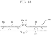
- an air bubble 32 is generated in the glass tube 100 , as shown in FIG. 13 .
- the glass tube 100 lies in the container 170 , an air bubble 32a is present in an upper portion of the internal portion of the luminous bulb portion 10 of the glass tube 100 .
- This air bubble 32a remains in the upper portion of the internal portion of the luminous bulb portion 10 of the glass tube 100, even if the glass tube 100 is rotated or moved. Therefore, the air bubble 32a prevents the pure water 160 from being in contact with the inner face of the luminous bulb portion 10 , so that the impurities present in the inner face of the luminous bulb portion 10 cannot be removed.
- the pure water 160 cannot flow in the internal portion of the glass tube 100 , even if the pure water 160 continues to flow in the container 170 . Therefore, the inner face of the glass tube 100 substantially cannot be cleaned.
- the reason is as follows. When the pure water 160 in the internal portion of the glass tube 100 stop flowing, even if the impurities present in the inner face of the glass tube 100 are dissolved in the pure water 160 , the impurities cannot go out from the glass tube 100 . Therefore, when glass tube 100 is dried after cleaning, the impurities are attached on the inner face of the glass tube 100 again.
- the pure water 160 flows in the internal portion of the glass, the inner face cannot be cleaned, although the outer face of the glass tube 100 can be cleaned.
- the inner diameter of the glass tube 100 is not so large that the flow of the pure water 160 in the glass tube 100 is not satisfactory, or rather the pure water 160 hardly flows.
- a method for cleaning a translucent tube for a discharge lamp having a luminous bulb portion includes the steps of introducing a cleaning fluid from one end of the translucent tube; and allowing the cleaning fluid to flow while bringing the cleaning fluid in contact with at least an inner face of the luminous bulb portion of an inner face of the translucent tube, thereby removing impurities attached on the inner face of the luminous bulb portion.
- the cleaning fluid is allowed to flow while being in contact with an outer face of the translucent tube in the same step, thereby removing impurities attached on the outer face of the translucent tube.
- the step of introducing a cleaning fluid includes the steps of disposing the translucent tube in a container for containing a cleaning liquid as the cleaning fluid such that ends of the tube are positioned in a substantially vertical direction; and injecting the cleaning liquid into the container.
- the step of removing impurities includes the steps of elevating a liquid surface of the cleaning liquid above an upper portion of the luminous bulb portion of the translucent tube for a discharge lamp; and lowering the liquid surface of the cleaning liquid below a lower portion of the luminous tube portion.
- the step of elevating the liquid surface of the cleaning liquid and the step of lowering the liquid surface of the cleaning liquid are repeated.
- the step of lowering the liquid surface of the cleaning liquid is performed such that the liquid surface of the cleaning liquid is lowered below a lower end of the translucent tube.
- the step of elevating the liquid surface of the cleaning liquid is performed such that the liquid surface of the cleaning liquid is elevated above an upper end of the translucent tube.
- the method further includes the step of discharging the cleaning liquid in the container from the container.
- the ending point of cleaning is determined by monitoring the concentration of the impurities contained in the cleaning liquid in the container.
- the translucent tube is disposed using a holding tool for holding a plurality of translucent tubes such that ends of the tubes are positioned in a substantially vertical direction.
- the cleaning liquid is one selected from the group consisting of ultrapure water (the value of resistance: e.g., about 10M ⁇ or more), pure water (the value of resistance: e.g., about 1M ⁇ or more), deionized water (the value of resistance: e.g., about 1M ⁇ - 10M ⁇ or more), hydrofluoric acid aqueous solution and hydrogen peroxide aqueous solution, and a combination of one of these cleaning liquids and cleaning fine particles.
- ultrapure water the value of resistance: e.g., about 10M ⁇ or more
- pure water the value of resistance: e.g., about 1M ⁇ or more
- deionized water the value of resistance: e.g., about 1M ⁇ - 10M ⁇ or more
- hydrofluoric acid aqueous solution and hydrogen peroxide aqueous solution the cleaning liquids and cleaning fine particles.
- a plurality of kinds of impurities are attached on the inner face of the luminous bulb portion as the impurities
- the method includes at least a first step of introducing a first cleaning liquid as the cleaning liquid from the one end of the translucent tube with respect to a first kind of impurities of the plurality of kinds of impurities, and a second step of introducing a second cleaning liquid other than the first cleaning liquid as the cleaning liquid from the one end of the translucent tube with respect to a second kind of impurities other than the first kind of impurities of the plurality of kinds of impurities.
- the cleaning fluid is either one of gas, liquid, or fine particle powder
- the step of removing impurities attached on the inner face of the luminous bulb portion is performed by discharging the cleaning fluid introduced from one end of the translucent tube for a discharge lamp from the other end of the translucent tube for a discharge lamp.
- the cleaning fluid is inert gas (e.g., argon gas or nitrogen gas).
- an apparatus for cleaning a translucent tube for a discharge lamp includes a container for accommodating a translucent tube for a discharge lamp having a luminous bulb portion and for containing a cleaning liquid; an injection pipe or an injection tube through which the cleaning liquid is injected into the container; a discharge pipe or a discharge tube through which the cleaning liquid in the container is discharged; and a concentration monitoring meter for monitoring a concentration of impurities that was attached on the translucent tube and is contained in the cleaning liquid in the container.
- the concentration monitoring meter has a function to determine an end of cleaning by comparing an electrical conductivity of the cleaning liquid in the container or the cleaning liquid discharged from the container with a reference value, an electrical conductivity of the cleaning liquid injected to the injection pipe or the injection tube being used as the reference value.
- the container has an airtight structure that prevents the cleaning liquid in the container from being in contact with air outside the container.
- a discharge lamp comprising a luminous bulb and sealing portions extending from the luminous bulb, the luminous bulb enclosing a luminous material and including a pair of electrodes opposed to each other therein
- the discharge lamp is produced by a method for producing a discharge lamp including the steps of preparing a translucent tube for a discharge lamp including a luminous bulb portion that becomes a luminous bulb of the discharge lamp, and side tube portions extending from the luminous bulb portion, the translucent tube having been subjected to a cleaning process; inserting an electrode assembly including metal foils and electrodes connected to the metal foils into the side tube portion such that the heads of the electrodes are positioned inside the luminous bulb portion; and forming the sealing portions by tightly attaching the metal foils of the electrode assembly to the side tube portions.
- the cleaning process includes the steps of (a) introducing a cleaning fluid from one end of a translucent tube for a discharge lamp including a luminous bulb portion that becomes a luminous bulb of the discharge lamp, and side tube portions extending from the luminous bulb portion; and (b) allowing the cleaning fluid to flow while bringing the cleaning fluid in contact with at least the inner face of the luminous bulb portion of the inner face of the translucent tube, thereby removing impurities attached on the inner face of the luminous bulb portion.
- the step (a) includes a step (a-1) of disposing the translucent tube in a container for containing a cleaning liquid as the cleaning fluid so that ends of the translucent tube are positioned in a substantially vertical direction; and a step (a-2) of injecting the cleaning liquid into the container.
- the step (b) includes a step (b-1) of elevating a liquid surface of the cleaning liquid above an upper portion of the luminous bulb portion of the translucent tube; and a step (b-2) of lowering the liquid surface of the cleaning liquid below a lower portion of the luminous tube portion.
- the discharge lamp as the luminous material, at least mercury, a rare gas and halogen are enclosed in the luminous bulb, and the luminous bulb is made substantially of quartz glass, and the electrodes are made substantially of tungsten, and the mole number of the halogen is larger than the sum of the total mole number of metal elements that have the property of bonding to the halogen and are present in the luminous bulb (except for tungsten and mercury), and the mole number of the tungsten present in the luminous bulb after evaporated from the electrodes during lamp operation.
- the mole number of the metal element Mi is mi
- the stoichiometric coefficient of the metal element Mi is ni
- the mole number of the halogen is larger than the sum of the total number ( ⁇ (mi ⁇ ni)) obtained by adding the numbers obtained by multiplying the mole number mi of the metal element Mi by the stoichiometric coefficient ni with respect to each kind of the metal elements Mi , and the mole number of the tungsten.
- the mole number of the halogen enclosed in the luminous bulb is not less than five times the total mole number of sodium (Na), potassium (K), lithium (Li), chromium (Cr), iron (Fe) and nickel (Ni) present in the luminous bulb.
- the discharge lamp is a mercury lamp in which a bulb wall load of the luminous bulb is 80W/cm 2 or more.
- a cleaning fluid is introduced from one end of a translucent tube for a discharge lamp (e.g., glass tube or ceramic tube for a discharge lamp), and the cleaning fluid is allowed to flow while bringing the cleaning fluid in contact with at least the inner face of the luminous bulb portion.
- a translucent tube for a discharge lamp e.g., glass tube or ceramic tube for a discharge lamp
- the cleaning fluid is allowed to flow while bringing the cleaning fluid in contact with at least the inner face of the luminous bulb portion.
- the cleaning fluid when the cleaning fluid is allowed to flow while bringing the cleaning fluid in contact with, not only the inner face of the luminous bulb portion, but also the outer face of the translucent tube, the impurities attached on the outer face of the translucent tube as well as the impurities attached on the inner face thereof can be removed.
- the impurities especially, fingerprints or oils and fats of workers
- the cleaning liquid is allowed to flow while being in contact with the inner face of the luminous bulb portion in the following manner.
- a translucent tube is disposed in a container in which a cleaning liquid is to be poured so that the ends of the tube are positioned in a substantially vertical direction, and then the liquid surface of the cleaning liquid is elevated above the upper portion of the luminous bulb portion. Thereafter, the liquid surface of the cleaning liquid is lowered below the lower portion of the luminous bulb portion.
- the cleaning liquid having a high content of impurities can be discharged from the tube, so that the impurities attached on the inner face of the translucent tube can be removed satisfactorily.
- the cleaning liquid having a high content of impurities can be discharged from the tube. Furthermore, this is also preferable, because the entire inner face of the translucent tube can be in contact with the cleaning liquid. It is more preferable to discharge the cleaning liquid in the container from the container, because the cleaning liquid containing impurities can be replaced by a cleaning liquid that has not been subjected to cleaning yet. Furthermore, when cleaning is performed while monitoring the concentration of the impurities contained in the cleaning liquid, it is possible to easily determine the time at which the impurities are removed completely (end of cleaning).
- the plurality of translucent tubes can be cleaned, so that working efficiency can be improved.
- the cleaning liquid ultrapure water, pure water, deionized water, hydrofluoric acid aqueous solution, and hydrogen peroxide aqueous solution can be used, and a combination of one of these cleaning liquids and cleaning fine particles can be used.
- the cleaning liquid for example, ultrapure water is used, an alkaline component can be removed satisfactorily.
- a first cleaning liquid is used with respect to a first kind of impurities
- a second cleaning liquid is used with respect to a second kind of impurities to clean the translucent tube.
- the cleaning fluid either gas, liquid, or fine particle powder can be used to remove the impurities attached on the inner face of the luminous bulb portion by discharging the cleaning fluid introduced from one end of the translucent tube for a discharge lamp from the other end of the translucent tube for a discharge lamp.
- the cleaning fluid for example, inert gas such as argon gas and nitrogen gas can be used.
- An apparatus for cleaning a translucent tube for a discharge lamp of the present invention includes an injection pipe (or injection tube) through which a cleaning liquid is injected into a container for accommodating the translucent tube for a discharge lamp, a discharge pipe (or discharge tube) through which the cleaning liquid is discharged from the container, and a concentration monitoring meter for monitoring the concentration of the impurities contained in the cleaning liquid in the container. Therefore, the impurity concentration can be monitored while cleaning, which can ensure the cleaning of the translucent tube for a discharge lamp. If the concentration monitoring meter has a function to determine the end of cleaning, the ending point of cleaning can be determined easily.
- the concentration monitoring meter for example, the time at which the electrical conductivity of the cleaning liquid in the container or the cleaning liquid discharged from the container is substantially equal to a reference value can be set as the ending point of cleaning. Furthermore, in the case where the container has an airtight structure so that the cleaning liquid in the container is not in contact with the air outside the container, it is possible to prevent impurities contained in the air outside the container from being mixed with the cleaning liquid in the container.
- the impurities are removed satisfactorily, so that the discharge lamp has higher performance (e.g., longer lifetime) than those in the prior art.
- cleaning fluid is introduced from one end of a translucent tube for a discharge lamp (e.g., glass tube for a discharge lamp), and the cleaning fluid is allowed to flow while bringing the cleaning fluid in contact with at least the inner face of the luminous bulb portion. Therefore, the impurities attached on the inner face of the luminous bulb portion can be removed satisfactorily. As a result, the impurities (e.g., alkaline components) attached on the inner face of the luminous bulb portion can be cleaned away to the same concentration level as that of the impurities of the material (quartz glass) constituting the glass tube for a discharge lamp. Therefore, the present invention can produce a discharge lamp having a long lifetime in which devitrification or the like can be prevented.
- a translucent tube for a discharge lamp e.g., glass tube for a discharge lamp
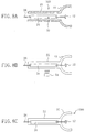
- FIGS. 1A to 1C are cross-sectional views schematically showing each process of a method for cleaning a translucent tube for a discharge lamp of en embodiment of the present invention.
- a glass tube 100 for a discharge lamp that is a translucent tube for a discharge lamp having a substantially spherical luminous bulb portion 10 and side tube portions 20 is prepared.
- the inner diameter and the glass thickness of the luminous bulb portion 10 of the glass tube 100 prepared in this embodiment are 6mm and 3mm, respectively.
- the inner diameter and the length in the longitudinal direction of the side tube portion 20 is 3.4mm and 250mm, respectively.
- the glass tube 100 is formed of quartz glass, for example, having an alkaline component concentration of 1 to 2ppm, preferably 1ppm or less.
- Impurities 30 are attached on the inner face (e.g., inner face 10a of the luminous bulb portion 10) of the prepared glass tube 100 before cleaning.
- Examples of the impurities 30 include alkaline components (Na, K etc.), silica powder, and organic substances.
- a glass tube for a discharge lamp is used, but the glass tube for a discharge lamp can be replaced by a ceramic tube for a discharge lamp.
- cleaning fluid 50 is introduced from one end 100a of the glass tube 100.
- the introduced cleaning fluid 50 flows while being in contact with the inner face 10a of the luminous bulb portion 10, as shown in FIG. 1B, and impurities 30 attached at least on the inner face 10a of the luminous bulb portion 10 are removed, as shown in FIG. 1C.
- the cleaning fluid 50 is discharged from the other end 100b of the glass tube 100, and thereafter new cleaning fluid 50' is introduced from the one end 100a of the glass tube 100, and the impurities 30 are removed by the cleaning fluid 50'.
- This introduction of cleaning fluid is repeated, and at the point where all the attached impurities 30 are removed, the glass tube 100 has been cleaned to the same concentration level as that of the impurities contained in the material (quartz glass) constituting the glass tube 100 .
- the cleaning fluid 50 flows while being in contact with the inner face 10a, so that the cleaning fluid 50 washes away the impurities 30. Furthermore, it is possible to remove the impurities 30 in an infinite dilution manner by replacing the cleaning fluid 50 in the glass tube 100 by new cleaning fluid.
- the cleaning method shown in FIG. 12 even if the glass tube 100 is moved more or less, the pure water in the glass tube 100 is hardly moved, and the pure water in the glass tube 100 can hardly be replaced. For this reason, in the cleaning method shown in FIG. 12 , removal of impurities is performed by diffusing the impurities in substantially stationary pure water. Therefore, the cleaning method of this embodiment can remove the impurities 30 from the tube more satisfactorily.
- the cleaning fluid 50 in this embodiment either gas (argon gas), liquid (cleaning liquid) or fine particle powder (quartz beads) can be used.
- gas argon gas
- liquid cleaning liquid
- fine particle powder fine particle powder
- a cleaning liquid is used as the cleaning fluid
- a glass tube for a discharge lamp is used as the translucent tube for a discharge lamp.
- the present invention is not limited by the following embodiments.
- a ceramic tube for a discharge lamp can replace the glass tube for a discharge lamp.
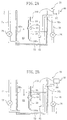
- FIGS. 2A and 2B schematically show each process of a cleaning method of Embodiment 1 .
- a glass tube 100 for a discharge lamp is disposed in a container 72 of a cleaning apparatus 70 provided with the container 72 for containing a cleaning liquid 60.
- the glass tube 100 is disposed so that the ends of the glass tube 100 are in a substantially vertical direction.
- One end 100a of the glass tube 100 is positioned in a lower portion of the container 72.
- the cleaning liquid 60 is injected into the container 72 through an injection pipe (or injection tube) 74 for injection of the cleaning liquid 60 into the container 72 .
- the amount of the cleaning liquid 60 to be injected can be adjusted by a valve 75 .
- the cleaning liquid 60 is injected into the container 72 , the liquid surface 60a of the cleaning liquid 60 is elevated. Therefore, after the cleaning liquid 60 is introduced from one end 100a of the glass tube 100, the cleaning liquid 60 in the glass tube 100 flows upward while being in contact with the inner face of the glass tube 100 .
- the injection of the cleaning liquid 60 continues and the cleaning liquid 60 in the glass tube 100 is allowed to flow while being in contact with the inner face 10a of the luminous bulb portion 10, so that the impurities (not shown) attached on the inner face 10a of the luminous bulb portion 10 are removed.
- the cleaning liquid 60 flows upward while in contact with not only the inner face of the glass tube 100 , but also the outer face of the glass tube 100 . Therefore, not only the impurities attached on the inner face 10a of the luminous bulb portion 10 , but also the impurities attached on the outer face (especially, outer face of the luminous bulb portion 10 ) of the glass tube 100 are removed.
- the outer face of the glass tube 100 finger prints or oils and fats of workers containing much of impurities such as sodium are readily attached. It is not preferable that they remain on the luminous bulb of a discharge lamp, because this may cause devitrification.
- the temperature is increased not only in the inner face of the luminous bulb, but also the outer face during lamp lighting, and therefore finger prints or oils and fats are burned and attached thereto, which may cause devitrification.
- the outer face of the glass tube 100 as well as the inner face thereof can be cleaned, so that such devitrification can be prevented effectively.
- the inner face and the outer face of the glass tube 100 can be cleaned at the same time, so that working efficiency is good.
- the entire inner face 10a of the luminous bulb portion 10 has been cleaned with the cleaning liquid 60.
- the injection of the cleaning liquid 60 from the injection pipe 74 continues so that the liquid surface 60a of the cleaning liquid 60 is elevated until the liquid surface reaches a predetermined height in the container 72 , preferably, above the upper end of the glass tube 100 .
- the cleaning liquid 60 can be in contact with the entire inner face of the glass tube 100 .
- the cleaning liquid 60 can be replaced by discharging the cleaning liquid 60 in the tube from the upper end of the glass tube 100 .
- dust is present on the liquid surface 60a , it is possible to prevent the dust from being attached and remaining on the inner face of the tube.
- the cleaning liquid 60 in the container 72 is discharged through a discharge pipe (discharge tube) 76 for discharge of the cleaning liquid 60 in the container 72 to lower the liquid surface 60a of the cleaning liquid 60 .
- the cleaning liquid 60 is injected into the container 72 through the injection pipe 74 in the state where both the valve 75 of the injection pipe 74 and the valve 75 of the discharge pipe 76 are open, so that the liquid surface 60a of the cleaning liquid 60 is elevated to the height of the uppermost portion 76h of the discharge pipe 76.
- the cleaning liquid is discharged (drained) automatically on the principle of siphon.
- the discharge liquid 60 can be completed without stopping the injection of the cleaning liquid 60 .
- the up and down of the liquid surface 60a can be repeated infinitely.
- the up and down of the liquid surface 60a can be performed by adjusting the valve 75 of the injection pipe 74 and the valve 75 of the discharge pipe 76 .
- the discharge pipe (liquid removing pipe) is provided in a lower portion of the container 72 or on the bottom face of the container 72 , so that the cleaning liquid 60 can be discharged from the discharge pipe. In this case, after the injection of the cleaning liquid 60 is stopped, the cleaning liquid 60 is discharged.
- the cleaning liquid 60 moves while being in contact with the inner face 10a of the luminous bulb portion 10.
- the cleaning liquid 60 in the tube is removed by lowering the liquid surface 60a below the lower end 100a of the glass tube 100, and the liquid surface 60a is elevated again by new cleaning liquid 60 that is constantly injected from the injection pipe 74 .
- cleaning can be performed while replacing the entire cleaning liquid 60 in the glass tube 100.
- the liquid surface 60a of the cleaning liquid 60 can be elevated again.
- the inner face of the glass tube 100 can be cleaned while replacing a part of the cleaning liquid 60 in the glass tube 100 by a part of the cleaning liquid 60 outside the tube.
- the liquid surface 60a is elevated and lowered by the injection and the discharge of the cleaning liquid 60 .
- the liquid surface 60a can be elevated and lowered by physically moving the glass tube 100 up and down (e.g., mechanically or manually).
- the glass tube 100 is cleaned by repeating elevating and lowering the liquid surface 60a a plurality of times.
- a set of elevating and lowering the liquid surface 60a is performed over about 5 minutes, and cleaning is carried out by performing the total of five sets.
- the end of cleaning can be determined by monitoring the concentration of the impurities contained in the cleaning liquid 60 in the container 72 .
- cleaning can be performed while monitoring with a concentration monitoring meter whether or not the concentration of the impurities in the cleaning liquid 60 to be injected to the injection pipe 74 and the concentration of the impurities in the cleaning liquid 60 in the container 72 are within a predetermined range (or substantially equal).
- concentration of the impurities in the cleaning liquid 60 discharged from the container 72 can be monitored instead of the concentration of the impurities of the cleaning liquid 60 in the container 72 .
- the concentration of the impurities contained in the cleaning liquid 60 can be measured, for example, with an electrical conductivity meter. More specifically, as shown in FIGS. 2A and 2B , using an electrical conductivity meter 82 for measuring the electrical conductivity of the cleaning liquid 60 in the container 72 and a concentration monitoring meter 80 provided with a monitor 84 showing the indicated value of the electrical conductivity meter 82 , the end of cleaning can be determined.
- the cleaning liquid (e.g., pure water or ultrapure water) 60 to be injected to the injection pipe 74 is poured, for example, in the container 72 , and the electrical conductivity of the cleaning liquid 60 is measured with the electrical conductivity meter 82 , and the indicated value obtained by the measurement is used as the reference value.
- the electrical conductivity of the cleaning liquid 60 in the container 72 is compared with the reference value, so that the end of cleaning can be determined.
- the electrical conductivity meter is placed in a cleaning liquid supply tank (not shown) of the cleaning liquid 60 to be injected to the injection pipe, and the indicated value from the electrical conductivity meter can be used as the reference value.
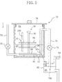
- FIG. 3 is a perspective view showing the structure of the cleaning apparatus 70 shown in FIG. 2 .
- FIG. 4 is a perspective view of a holding tool 90 for holding a plurality of glass tubes 100 for a discharge lamp positioned substantially in the vertical direction.
- the cleaning apparatus 70 shown in FIG. 3 includes a container 72 for containing a cleaning liquid 60 into the container 72 , an injection pipe 74 through which the cleaning liquid 60 is injected, and a discharge pipe 76 through which the cleaning liquid 60 in the container 72 is discharged.
- the cleaning apparatus 70 further includes a concentration monitoring meter 80 (see FIG. 2) for monitoring the concentration of the impurities contained in the cleaning liquid 60 in the container 72 (impurities attached on the glass tube 100 ), which is not shown in FIG. 3 .
- the container 72 , the injection pipe (or injection tube) 74 , and the discharge pipe (or discharge tube) 76 of the cleaning apparatus 70 are made of polyvinylchloride (thickness: for example, about 5mm) so as to prevent impurities of the materials constituting these members from being mixed with the cleaning liquid 60 .
- polyvinylchloride e.g., Teflon (registered trademark)
- PTFE e.g., Teflon (registered trademark)
- the upper face of the container 72 is open, and glass tube 100 is inserted from the opening on the upper face so that glass tube 100 can be disposed in the container 72. After disposing the glass tube 100 in the container 72 , it is desired to set a lid 78 on the upper face of the container 72 so as to shut off dust or the like from the container 72 .
- the upper face and the lower face of the container 72 are squares having a side of about 310mm, and the height of the container 72 is, for example, about 505mm.
- the shape of the container 72 may be a rectangle having rectangular top and bottom faces, or may be a cylinder having circular top and bottom faces.
- the injection pipe 74 has one end 74a from which the cleaning liquid (e.g., pure water) 60 is introduced, and the other end 74b from which the cleaning liquid 60 is supplied to the container 72 .
- the one end 74a is positioned outside the container 72
- the other end 74b is positioned in the container 72 .
- a hose made of polyvinylchloride can be connected to the one end 74a .
- the injection pipe 74 penetrates the side of the container 72 at a predetermined portion 74c , and a valve 75 for adjusting the amount of the cleaning liquid 60 to be injected is provided between the one end 74a and the other end 74b of the injection pipe 74 .
- the discharge pipe 76 has one end 76a positioned in the container 72 and the other end 76b positioned outside the container 72 .
- the one end 76a of the discharge pipe 76 is provided in a lower portion of the container 72 , preferably in a portion lower than the lower end of the glass tube 100 disposed in the container 72 .
- the one end 76a of the discharge pipe 76 is provided in a portion lower than the lower end of the disposed glass tube 100, the following advantage is provided.
- the cleaning liquid 60 is discharged, the liquid surface 60a of the cleaning liquid 60 can be lowered below the lower end of the glass tube 100 . As a result, the entire cleaning liquid 60 in the tube can be let out from the glass tube 100.
- the uppermost portion 76h of the discharge pipe 76 in a portion higher than the upper portion of the luminous bulb portion 10 of the disposed glass tube 100 , when discharging the cleaning liquid 60 from the discharge pipe 76 using the principle of siphon. It is more preferable to provide the uppermost portion 76h in a portion higher than the upper end of the disposed glass tube 100. Since the valve 75 is provided in the discharge pipe 76 , discharge can be adjusted and controller by the valve 75 . In this embodiment, apart from the discharge pipe, a pipe 77 for liquid removal provided with a valve 75 for the purpose of removing the cleaning liquid 60 is provided in a lower portion of the side of the container 72 . Therefore, the cleaning method of this embodiment can be performed by using the pipe 77 for liquid removal as the discharge pipe without using the discharge pipe 76 .
- the holding tool 90 of FIG. 4 includes a holding plate 94 having openings 98 through which the side tube portions 20 of the glass tube 100 pass and the luminous bulb portions 10 do not pass, and a supporting rod 92 for supporting the holding plate 94 .
- the holding plate 94 is attached to the supporting rod 92 that the holding plate 94 is substantially horizontal, so that the glass tubes 100 can be positioned in the substantially vertical direction by inserting the glass tubes 100 into the openings 98 of the holding plate 94 .
- About one hundred openings 98 are provided in the holding plate 94 , and therefore, using the holding tool 90 , about one hundred glass tubes 100 can be cleaned at one time.
- the middle plate 95 that prevents the side tube portions 20 of the glass tubes 100 from moving freely
- a lower plate 96 that is provided under the middle plate 95 and is to be disposed on a stand 97 .
- the middle plate 95 and the lower plate 96 are also supported by the supporting rod 92 , and when the glass tubes 100 are set into the holding tool 90 , the lower ends of the glass tubes 100 are positioned between the middle plate 95 and the lower plate 96 .
- the lower plate 96 and the stand 97 are provided with openings through which the glass tubes pass, but it is desired that the lower plate 96 and the stand 97 are provided with the openings 98 so that the cleaning liquid 60 can be let in and out satisfactorily. Furthermore, this is preferable, because the same member as those of the upper plate 94 and the middle plate 95 can be used to produce the tool.
- a handle 92a used to lift the holding tool 90 is formed in an upper portion of the supporting rod 92 , and the holding tool 90 can be disposed in the container 72 of the cleaning apparatus 70 with the handle 92a. Therefore, after a plurality of glass tubes 100 are set in the holding portion 90, the stand 97 is disposed on the bottom face of the container 72 , and then the holding tool 90 is moved into the container 72 with the handle 92a , so that each of the plurality of glass tubes 100 can be disposed in the container 72 , each positioned in a substantially vertical direction.
- the holding tool 90 is stabilized in the container 72 by its self-weight, and thus the glass tubes 100 can be positioned stably in the container by the holding tool 90 .
- the stand 97 supporting the holding tool 90 is larger that the lower plate 96 of the holding tool 90 , and a notch 97a is provided in the stand 97 so that a portion in the vicinity of the one end 76a of the discharge pipe 76 is not overlapped with the stand 97, when the stand 97 is disposed on the bottom face of the container 72 .
- an opening provided in the lower plate 96 of the holding tool 90 is matched with the opening provided in the stand 97 , because the cleaning liquid 60 can be let in and out satisfactorily.
- the members (e.g., the holding plate 94 and the supporting rod 92 ) constituting the holding tool 90 are formed of, for example, polyvinylchloride so as to prevent impurities from being mixed in the cleaning liquid 60.
- a gap h 1 between the upper plate 94 and the middle plate 95 is for example, about 100 mm.
- a gap h 2 between the upper plate 94 and the lower plate 96 is for example, about 165mm, and a gap h 3 between the upper plate 94 and the handle 92a is for example, about 200mm.
- the container 72 can be of an airtight structure. More specifically, after the holding tool 90 in which glass tubes 100 are set is disposed in the container 72 , an inert gas (e.g., Ar) 84 is filled in the container 72 , and then a lid 78 is attached so that the opening on the top face of the container 72 is sealed.
- an inert gas e.g., Ar
- a discharged liquid receptacle 86 is provided in an outlet (the other end) 76b of the discharge pipe 76 and an inert gas 84 is filled in the discharged liquid receptacle 86.
- Alkaline components are contained in the air in some concentration, and the concentration is larger in seaside areas. Therefore, it is preferable to use the container 72 of an airtight structure to clean the glass tubes 100 in order to obtain the glass tubes 100 whose impurities level is maintained at the level of the original material (quartz glass).
- Embodiment 1 a method for cleaning a glass tube for a discharge using one kind of cleaning liquid (e.g., pure water) has been described, but the present invention can apply to a method for cleaning a glass tube for a discharge lamp to remove a plurality of kinds of impurities with a plurality kinds of cleaning liquid.
- a cleaning method of Embodiment 2 will be described with reference to FIG. 6 . The same description as in Embodiment 1 will be omitted or simplified.
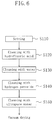
- FIG. 6 is a flowchart showing each step of the cleaning method of this embodiment.
- a glass tube 100 for a discharge lamp is set in the holding tool 90 shown in FIG. 4 (step S11 0 ), and the holding tool 90 in which the glass tube 100 is set is disposed in a container 72 of a first cleaning apparatus 70 (see FIG. 3).
- a hydrofluoric acid aqueous solution is supplied as the cleaning liquid 60 to the container 72 of the first cleaning apparatus 70 , and the liquid surface 60a (liquid surface of hydrofluoric acid aqueous solution) in the container 72 of the first cleaning apparatus 70 is elevated and lowered, as shown in FIG. 2 , so that silica powder attached on the glass tube 100 is removed (step S120).
- step S120 the holding tool 90 with the glass tube 100 set is taken out from the first cleaning apparatus 70 , and then is disposed in a container 72 in a second cleaning apparatus 70 using water as the cleaning liquid 60 . Thereafter, the glass tube 100 is cleaned with the second cleaning apparatus 70 to remove the hydrofluoric acid used in step S120 (step S130 ).
- the holding tool 90 with the glass tube 100 set is taken out from the second cleaning apparatus 70 , and then is disposed in a container 72 in a third cleaning apparatus 70 using hydrogen peroxide aqueous solution (hydrogen peroxide solution) as the cleaning liquid 60 . Thereafter, the glass tube 100 is cleaned with the third cleaning apparatus 70 to remove organic substances (including carbon dioxide) and metal impurities (step S140 ).
- the holding tool 90 with the glass tube 100 set is taken out from the third cleaning apparatus 70, and then is disposed in a container 72 in a fourth cleaning apparatus 70 using ultrapure water as the cleaning liquid 60 .
- the glass tube 100 is cleaned with the fourth cleaning apparatus 70 to remove alkaline components (Na, K, etc.) attached onto the inner face of the glass tube 100 (step S150 ).
- vacuum drying is performed, for example, with a vacuum drier.
- argon gas is introduced from one end of the glass tube 100 , and allowed to flow while being in contact with the inner face of the glass tube 100 . Then, argon gas is discharged from the other end of the glass tube 100 . Such flow of argon allows the air in the glass tube 100 to be purged by the argon gas, so that the cleaned state after step S150 can be maintained.
- the purge of the air in the glass tube 100 by argon is also advantageous in that handling of the glass tube 100 becomes easy.
- fine powder particles e.g., quartz beads
- the fine powder particles can be introduced from one end of the glass tube 100 , and the fine powder particles are brought in contact with the inner face of the glass tube 100 , so that impurities or dust attached on the inner face of glass tube 100 (especially inner face 10a of the luminous bulb portion 10) can be removed.
- the translucent tube for a discharge lamp that has been cleaned by the cleaning method of the above described methods is used to produce a discharge lamp.
- a discharge lamp produced with the translucent tube for a discharge lamp that has been cleaned by the cleaning method of the above described methods will be described with reference to FIGS. 7 to 11 .
- the same description as in the above embodiments will be omitted or simplified.
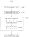
- FIG. 7 is a flowchart showing a production process of a discharge lamp of this embodiment.
- a quartz glass tube for a discharge lamp is prepared as a translucent tube for a discharge lamp (step S100).
- the glass tube prepared in this embodiment is the same as that of Embodiment 1 (see FIGS. 1 , 2A and 2B or the like).
- a glass tube for a discharge lamp is used, but a ceramic tube for a discharge can replace the glass tube for a discharge lamp.
- step S200 the glass tube is cleaned in the manner as described in the above embodiments.
- This step provides a glass tube that has been cleaned to the level of the impurities contained in the material (quartz glass) constituting the glass tube.
- a known lamp production process (step S300 ) is performed, so that a discharge lamp is completed.
- the lamp production process primarily includes an electrode insertion process (step S310) and a sealing portion formation process (step S320). These processes will be described briefly with reference to FIGS. 8A and 8C .
- an electrode assembly 50 including a metal foil (Mo foil) 24 and an electrode 12 connected to the metal foil 24 is inserted into the side tube portion 20 of the cleaned glass tube 100 (step S310).
- the electrode assembly 50 is inserted so that the head of the electrode 12 is positioned inside the luminous bulb portion 10 and the metal foil 24 is positioned inside the side tube portion 20 .
- a coil is wound around the head of the electrode 12 , and the coil has a function to reduce the temperature at the electrode head during lamp operation.
- An external lead 26 is connected to the metal foil 24 of the electrode assembly 50 on the side opposite to the side connected to the electrode 12 .
- the pressure in the glass tube 100 is reduced (e.g., less than one atmospheric pressure), and the side tube portion 20 of the glass tube 100 is heated and melted with a burner 54 , so that the side tube portion 20 and the metal foil 24 are attached so that the sealing portion 22 is formed (sealing portion formation process S320).
- a rare gas, halogen and mercury are enclosed in the luminous bulb portion 10, and then the other side tube portion 20 is subjected to the electrode insertion process S310 and the sealing portion formation process S320, and a pair of sealing portions 22 seals the luminous bulb 10.
- a discharge lamp 1000 can be obtained.
- the impurities are removed more satisfactorily than an uncleaned glass tube or a glass tube cleaned by the cleaning method shown in FIG. 12 , so that the discharge lamp of this embodiment can exhibit more excellent characteristics (e.g., longer lifetime) than those of conventional lamps
- FIG. 9 shows the structure of the discharge lamp 1000 of this embodiment.
- the discharge lamp shown in FIG. 9 is a mercury lamp (e.g., high pressure mercury or ultra high pressure mercury lamp), and includes a luminous bulb 10 made substantially of quartz glass and a pair of electrodes 12 and 12' disposed in a space (discharge space) 15 in the luminous bulb 10 and made substantially of tungsten.
- a mercury lamp e.g., high pressure mercury or ultra high pressure mercury lamp
- a luminous bulb 10 made substantially of quartz glass and a pair of electrodes 12 and 12' disposed in a space (discharge space) 15 in the luminous bulb 10 and made substantially of tungsten.
- discharge space 15 of the luminous bulb 10 at least mercury 18 , and a rare gas and halogen are enclosed.
- the main purposes for this enclosure are as follows.
- the mercury 18 is enclosed as a luminous material
- the rare gas is enclosed as a gas for smooth start, and halogen is enclosed to activate the halogen cycle.
- the mole number of halogen enclosed in the luminous bulb 10 is larger than the sum of the total mole number of metal elements that have the property of bonding to halogen (except for tungsten and mercury) and are present in the luminous bulb 10 , and the mole number of tungsten that is evaporated from the electrodes 12 and 12' during lamp operation and is present in the luminous bulb 10 .
- Typical examples of metal elements having the property of bonding to halogen are alkali metal elements (Na, K, etc.), when excluding tungsten element and mercury element.
- a preferable mole number of halogen to be enclosed is as follows.
- the mole number of halogen of a metal element Mi is mi
- the stoichiometric coefficient of the metal element Mi is ni
- the mole number of halogen is larger than the sum of the total number ( ⁇ (mi ⁇ ni)) obtained by adding the numbers obtained by multiplying the mole number mi of the metal element Mi by the stoichiometric coefficient ni with respect to each kind of the metal elements Mi , and the mole number of tungsten.
- Such a mole number of enclosed halogen can be realized by making it not less than five times the total mole number of sodium (Na), potassium (K), lithium (Li), chromium (Cr), iron (Fe) and nickel (Ni).
- Halogen is for example, bromine.
- Halogen is not necessarily enclosed in the form of a single substance, but can be in the form of a halogen precursor. In this embodiment, halogen is enclosed in the form of CH 2 Br 2 .
- the conditions of the discharge lamp 1000 of this embodiment are for example, as follows.
- the inner volume (volume of the discharge space) of the luminous bulb 10 is about 0.2cc (about 0.2cm 3 ), and about 30mg of mercury 18 (the amount of mercury per unit inner volume of the luminous bulb: about 150mg/cc), argon gas (not shown) with about 20KPa at room temperature, and CH 2 Br 2 (not shown) with about 60Pa are enclosed in the luminous bulb 10 .
- the outer diameter of the luminous bulb 10 is about 13mm, and the glass thickness of the luminous bulb 10 is about 3mm.
- the bulb wall load of the luminous bulb is 80W/cm 2 or more, and the discharge lamp is of a short arc type in which the distance between the electrodes is short.
- the distance between the electrodes is for example, about 5 mm to about lmm, and for example, the distance between the electrodes is about 1.5mm.
- the metal foil e.g., molybdenum foil
- An external lead (Mo rod) 26 made of molybdenum is electrically connected to one end of the metal foil 24.
- the rated power is 150W (corresponding to a bulb wall load of about 85W/cm 2 ).
- the discharge lamp 1000 of Embodiment 3 can be formed into a lamp 1200 provided with a reflecting mirror in combination with a reflecting mirror 180, as shown in FIG. 10. If the lamp 1200 provided with a reflecting mirror is combined with a housing (not shown) for supporting the lamp, a lamp unit can be formed.
- FIG. 10 schematically shows a cross-section of the lamp 1200 provided with a reflecting mirror.
- the lamp 1200 provided with a reflecting mirror includes the discharge lamp 1000 including a substantially spherical luminous portion 10 and a pair of sealing portions 22 , and a reflecting mirror 180 for reflecting light emitted from the discharge lamp 1000 .
- the reflecting mirror 180 is designed to reflect the radiated light from the discharge lamp 1000 so that the light becomes, for example, a parallel luminous flux, a condensed luminous flux converged on a predetermined small area, or a divergent luminous flux equal to that emitted from a predetermined small area.
- a parabolic reflector or an ellipsoidal mirror can be used, for example.
- a lamp base 55 is attached to one of the sealing portion 22' of the discharge lamp 1000, and an external lead 26 extending from the sealing portion 22 and the lamp base 55 are electrically connected.
- the sealing portion 22 attached with the lamp base 55 is adhered to the reflecting mirror 180 , for example, with an inorganic adhesive (e.g., cement) so that they are integrated.
- a lead wire 185 is electrically connected to the external lead 26 of the sealing portion 22 positioned on the front opening side of the reflecting mirror 180 .
- the lead wire 185 extends from the external lead 26 to the outside of the reflecting mirror 180 through an opening 182 for a lead wire of the reflecting mirror 180 .
- a front glass can be attached to the front opening of the reflecting mirror 180 .
- Such a lamp unit can be attached to an image projection apparatus such as a projector employing liquid crystal or DMD, and is used as the light source for the image projection apparatus.
- the discharge lamp and the lamp unit of the above embodiments can be used, not only as the light source for image projection apparatuses, but also as a light source for general illumination or ultraviolet steppers, or a light source for an athletic meeting stadium, a light source for headlights of automobiles or the like.
- the lamp enclosing mercury in an amount of 150mg/cc has been described as an example.
- the amount is not limited thereto, and can be larger or smaller.
- the case where the mercury vapor pressure is about 20MPa (the case of so-called ultra high pressure mercury lamp) has been described.
- the present invention can apply to a high pressure mercury lamp in which a mercury vapor pressure is about 1MPa.
- the gap (arc length) between the pair of electrodes 12 can be short, or can be longer than that.
- the high pressure discharge lamps of Embodiment 3 can be used by either lighting method, alternating current lighting or direct current lighting.
- a metal halide can be enclosed. More specifically, in Embodiment 3 , a mercury lamp employing mercury as a luminous material has been described as an example of a high pressure discharge lamp. However, the present invention can apply to a high pressure discharge lamp such as a metal halide lamp in which a metal halide is enclosed. However, in the configuration of the discharge lamp of Embodiment 3 , it is preferable that the amount of enclosed mercury is about 200mg/cc or less.
- the amount of enclosed mercury can be larger than 200mg/cc.
- the thermal conductivity of the gas in the luminous bulb 10 becomes high. Therefore, the heat of discharge plasma easily propagates to the electrodes 12 or the luminous bulb 10 (quartz glass), which further raises the temperature, so that impurities more significantly leak from the glass or the electrodes. Therefore, in the case where mercury is enclosed in an amount of more than 200mg/cc, the advantage of the lamp 1000 of Embodiment 3 produced with a glass tube made of a material having a high purity that has been cleaned satisfactorily is highly distinguished.
- the bulb wall load is about 80W/cm 2
- the bulb wall load is not limited thereto.
- the bulb wall load can be smaller or larger than that.
- a lamp is operated in a high temperature, and therefore impurities significantly leak from the glass or electrodes. Therefore, the advantage of the lamp 1000 of Embodiment 3 produced with a glass tube made of a material having a high purity is highly distinguished.
- the bulb wall load is about 100W/cm 2 or less.
- the bulb wall load can be larger than 100W/cm 2 .
- the rated power is 150W
- the rated power is not limited thereto, and can be more than 150W or less than 150W.
- the configuration of the discharge lamp of Embodiment 3 is particularly suitable for a lamp having a comparatively large power of 50W or more. Since a lamp having a large power is operated in a higher temperature, impurities significantly leak from the glass or the electrodes. Therefore, the advantage of the lamp 1000 of Embodiment 3 made of a material having a high purity is highly distinguished.
- a lamp enclosing bromine (Br) as halogen has been described as an example, but halogen can be replaced by chlorine (Cl) or iodine (I).
Landscapes
- Engineering & Computer Science (AREA)
- Manufacturing & Machinery (AREA)
- Cleaning By Liquid Or Steam (AREA)
- Vessels And Coating Films For Discharge Lamps (AREA)
- Cleaning In General (AREA)
Abstract
Description
Claims (20)
- A method for cleaning a translucent tube for a discharge lamp having a luminous bulb portion, comprising the steps of:introducing a cleaning fluid from one end of the translucent tube; andallowing the cleaning fluid to flow while bringing the cleaning fluid in contact with at least an inner face of the luminous bulb portion of an inner face of the translucent tube, thereby removing impurities attached on the inner face of the luminous bulb portion.
- The method for cleaning a translucent tube for a discharge lamp of claim 1, wherein in the step of removing impurities, the cleaning fluid is allowed to flow while being in contact with an outer face of the translucent tube in the same step, thereby removing impurities attached on the outer face of the translucent tube.
- The method for cleaning a translucent tube for a discharge lamp of claim 1, wherein the step of introducing a cleaning fluid includes the steps of:disposing the translucent tube in a container for containing a cleaning liquid as the cleaning fluid such that ends of the tube are positioned in a substantially vertical direction; andinjecting the cleaning liquid into the container, andthe step of removing impurities includes the steps of:elevating a liquid surface of the cleaning liquid above an upper portion of the luminous bulb portion of the translucent tube for a discharge lamp; andlowering the liquid surface of the cleaning liquid below a lower portion of the luminous tube portion.
- The method for cleaning a translucent tube for a discharge lamp of claim 3, wherein the step of elevating the liquid surface of the cleaning liquid and the step of lowering the liquid surface of the cleaning liquid are repeated.
- The method for cleaning a translucent tube for a discharge lamp of claim 3, wherein the step of lowering the liquid surface of the cleaning liquid is performed such that the liquid surface of the cleaning liquid is lowered below a lower end of the translucent tube.
- The method for cleaning a translucent tube for a discharge lamp of claim 3, wherein the step of elevating the liquid surface of the cleaning liquid is performed such that the liquid surface of the cleaning liquid is elevated above an upper end of the translucent tube.
- The method for cleaning a translucent tube for a discharge lamp of claim 3, further comprising the step of discharging the cleaning liquid in the container from the container.
- The method for cleaning a translucent tube for a discharge lamp of claim 3, wherein an ending point of cleaning is determined by monitoring a concentration of the impurities contained in the cleaning liquid in the container.
- The method for cleaning a translucent tube for a discharge lamp of claim 3, wherein the translucent tube is disposed using a holding tool for holding a plurality of translucent tubes such that ends of the tubes are positioned in a substantially vertical direction.
- The method for cleaning a translucent tube for a discharge lamp of claim 3, wherein the cleaning liquid is one selected from the group consisting of ultrapure water, pure water, deionized water, hydrofluoric acid aqueous solution and hydrogen peroxide aqueous solution, and a combination of one of these cleaning liquids and cleaning fine particles.
- The method for cleaning a translucent tube for a discharge lamp of claim 3, wherein a plurality of kinds of impurities are attached on the inner face of the luminous bulb portion as the impurities, the method comprising at least:a first step of introducing a first cleaning liquid as the cleaning liquid from the one end of the translucent tube with respect to a first kind of impurities of the plurality of kinds of impurities, anda second step of introducing a second cleaning liquid other than the first cleaning liquid as the cleaning liquid from the one end of the translucent tube with respect to a second kind of impurities other than the first kind of impurities of the plurality of kinds of impurities.
- The method for cleaning a translucent tube for a discharge lamp of claim 1, wherein the cleaning fluid is either one of gas, liquid, or fine particle powder, and
the step of removing impurities attached on the inner face of the luminous bulb portion is performed by discharging the cleaning fluid introduced from one end of the translucent tube for a discharge lamp from the other end of the translucent tube for a discharge lamp. - The method for cleaning a translucent tube for a discharge lamp of claim 12, wherein the cleaning fluid is inert gas.
- An apparatus for cleaning a translucent tube for a discharge lamp comprising:a container for accommodating a translucent tube for a discharge lamp having a luminous bulb portion and for containing a cleaning liquid;an injection pipe or an injection tube through which the cleaning liquid is injected into the container;a discharge pipe or a discharge tube through which the cleaning liquid in the container is discharged; anda concentration monitoring meter for monitoring a concentration of impurities that was attached on the translucent tube and is contained in the cleaning liquid in the container.
- The apparatus for cleaning a translucent tube for a discharge lamp of claim 14, wherein the concentration monitoring meter has a function to determine an end of cleaning by comparing an electrical conductivity of the cleaning liquid in the container or the cleaning liquid discharged from the container with a reference value, an electrical conductivity of the cleaning liquid injected to the injection pipe or the injection tube being used as the reference value.
- The apparatus for cleaning a translucent tube for a discharge lamp of claim 14, wherein the container has an airtight structure that prevents the cleaning liquid in the container from being in contact with air outside the container.
- A discharge lamp comprising a luminous bulb and sealing portions extending from the luminous bulb, the luminous bulb enclosing a luminous material and including a pair of electrodes opposed to each other therein,
wherein the discharge lamp is produced by a method for producing a discharge lamp comprising the steps of:preparing a translucent tube for a discharge lamp including a luminous bulb portion that becomes a luminous bulb of the discharge lamp, and side tube portions extending from the luminous bulb portion, the translucent tube having been subjected to a cleaning process;inserting an electrode assembly including metal foils and electrodes connected to the metal foils into the side tube portion such that heads of the electrodes are positioned inside the luminous bulb portion; andforming the sealing portions by tightly attaching the metal foils of the electrode assembly to the side tube portions,the cleaning process comprising the steps of:(a) introducing a cleaning fluid from one end of a translucent tube for a discharge lamp including a luminous bulb portion that becomes a luminous bulb of the discharge lamp, and side tube portions extending from the luminous bulb portion; and(b) allowing the cleaning fluid to flow while bringing the cleaning fluid in contact with at least the inner face of the luminous bulb portion of the inner face of the translucent tube, thereby removing impurities attached on the inner face of the luminous bulb portion,wherein the step (a) includes a step (a-1) of disposing the translucent tube in a container for containing a cleaning liquid as the cleaning fluid such that ends of the translucent tube are positioned in a substantially vertical direction; and a step (a-2) of injecting the cleaning liquid into the container, andthe step (b) includes a step (b-1) of elevating a liquid surface of the cleaning liquid above an upper portion of the luminous bulb portion of the translucent tube; and a step (b-2) of lowering the liquid surface of the cleaning liquid below a lower portion of the luminous tube portion. - The discharge lamp of claim 17, whereinat least mercury as the luminous material, a rare gas and halogen are enclosed in the luminous bulb, and the luminous bulb is made substantially of quartz glass, and the electrodes are made substantially of tungsten, anda mole number of the halogen is larger than a sum of a total mole number of metal elements that have a property of bonding to the halogen and are present in the luminous bulb (except for tungsten and mercury), and a mole number of the tungsten present in the luminous bulb after evaporated from the electrodes during lamp operation.
- The discharge lamp of claim 18, wherein
the mole number of the halogen enclosed in the luminous bulb is not less than five times the total mole number of sodium (Na), potassium (K), lithium (Li), chromium (Cr), iron (Fe) and nickel (Ni) present in the luminous bulb. - The discharge lamp of claim 17, wherein
the discharge lamp is a mercury lamp in which a bulb wall load of the luminous bulb is 80W/cm2 or more.
Applications Claiming Priority (2)
| Application Number | Priority Date | Filing Date | Title |
|---|---|---|---|
| JP2000135544 | 2000-05-09 | ||
| JP2000135544 | 2000-05-09 |
Publications (2)
| Publication Number | Publication Date |
|---|---|
| EP1154455A2 true EP1154455A2 (en) | 2001-11-14 |
| EP1154455A3 EP1154455A3 (en) | 2003-12-03 |
Family
ID=18643608
Family Applications (1)
| Application Number | Title | Priority Date | Filing Date |
|---|---|---|---|
| EP01111047A Withdrawn EP1154455A3 (en) | 2000-05-09 | 2001-05-08 | Method and apparatus for cleaning translucent tube for discharge lamp, and discharge lamp |
Country Status (5)
| Country | Link |
|---|---|
| US (1) | US20020002988A1 (en) |
| EP (1) | EP1154455A3 (en) |
| KR (1) | KR20010106223A (en) |
| CN (1) | CN1323052A (en) |
| TW (1) | TW513328B (en) |
Cited By (1)
| Publication number | Priority date | Publication date | Assignee | Title |
|---|---|---|---|---|
| EP1526564A1 (en) * | 2003-10-20 | 2005-04-27 | Harison Toshiba Lighting Corporation | Sc-Na-metal halide lamp and method of manufacture |
Families Citing this family (3)
| Publication number | Priority date | Publication date | Assignee | Title |
|---|---|---|---|---|
| US6969419B1 (en) * | 1999-05-06 | 2005-11-29 | Segars California Partners Lp | Method for removing gas bubbles from a fluid-containing chamber |
| KR101153764B1 (en) * | 2003-02-18 | 2012-06-13 | 고에키자이단호진 고쿠사이카가쿠 신고우자이단 | Fluorescent lamp and its manufacturing method |
| TWI418417B (en) * | 2009-03-27 | 2013-12-11 | Brother Ind Ltd | Tool cleaning equipment |
Family Cites Families (7)
| Publication number | Priority date | Publication date | Assignee | Title |
|---|---|---|---|---|
| GB719269A (en) * | 1952-07-11 | 1954-12-01 | British Thomson Houston Co Ltd | Improvements relating to the manufacture of electric discharge lamps |
| US4891555A (en) * | 1985-11-15 | 1990-01-02 | General Electric Company | Metal vapor discharge lamps |
| JPS63294659A (en) * | 1987-05-27 | 1988-12-01 | Hitachi Ltd | Metal halide lamp |
| US5300859A (en) * | 1987-11-12 | 1994-04-05 | Yissum Research Development Company Of The Hebrew University Of Jerusalem | IR-radiation source and method for producing same |
| US5057751A (en) * | 1990-07-16 | 1991-10-15 | General Electric Company | Protective coating for high-intensity metal halide discharge lamps |
| US5133682A (en) * | 1990-11-02 | 1992-07-28 | Gte Products Corporation | Method and mold for fabricating an arc tube for an arc discharge lamp |
| US5246025A (en) * | 1991-03-28 | 1993-09-21 | Cawlfield B Gene | Controlled fluid agitation method and apparatus |
-
2001
- 2001-05-08 EP EP01111047A patent/EP1154455A3/en not_active Withdrawn
- 2001-05-09 US US09/851,782 patent/US20020002988A1/en not_active Abandoned
- 2001-05-09 CN CN01115837A patent/CN1323052A/en active Pending
- 2001-05-09 KR KR1020010025139A patent/KR20010106223A/en not_active Withdrawn
- 2001-05-09 TW TW090111070A patent/TW513328B/en not_active IP Right Cessation
Cited By (2)
| Publication number | Priority date | Publication date | Assignee | Title |
|---|---|---|---|---|
| EP1526564A1 (en) * | 2003-10-20 | 2005-04-27 | Harison Toshiba Lighting Corporation | Sc-Na-metal halide lamp and method of manufacture |
| US7233110B2 (en) | 2003-10-20 | 2007-06-19 | Harison Toshiba Lighting Corp. | Metal halide lamp and lighting device |
Also Published As
| Publication number | Publication date |
|---|---|
| US20020002988A1 (en) | 2002-01-10 |
| KR20010106223A (en) | 2001-11-29 |
| TW513328B (en) | 2002-12-11 |
| EP1154455A3 (en) | 2003-12-03 |
| CN1323052A (en) | 2001-11-21 |
Similar Documents
| Publication | Publication Date | Title |
|---|---|---|
| CN1305103C (en) | High-voltage dicharge lamp and tamp assembly | |
| CN100449678C (en) | Short arc ultra-high pressure mercury lamp | |
| KR101031381B1 (en) | Excimer discharge lamp | |
| RU2451361C2 (en) | Ceramic burner for ceramic metal halide lamp | |
| US8288946B2 (en) | Discharge lamp with a pressure-resistant hydrogen getter | |
| EP1154455A2 (en) | Method and apparatus for cleaning translucent tube for discharge lamp, and discharge lamp | |
| JP3330590B2 (en) | Method for cleaning translucent tube for discharge lamp and discharge lamp | |
| TWI303840B (en) | ||
| EP1607997B1 (en) | Method for producing high-pressure discharge lamp, high-pressure discharge lamp and lamp unit using such high-pressure discharge lamp, and image display | |
| JP3626324B2 (en) | Manufacturing method of ceramic discharge lamp | |
| JP4466731B2 (en) | Discharge lamp | |
| JPH0785839A (en) | Double tube discharge lamp and photochemical reaction device using the same | |
| CN100470714C (en) | Short arc ultra high pressure discharge lamp | |
| JP4134927B2 (en) | Excimer lamp | |
| TWI344320B (en) | Short arc type discharge lamp operating apparatus, ultraviolet irradiation apparatus and method of ultraviolet irradiating | |
| JPH04248247A (en) | Protective film for high-luminous intensity metal halide discharge lamp | |
| US6838823B2 (en) | Discharge lamp | |
| CN101640163B (en) | excimer lamp | |
| JP2010225306A (en) | High-pressure discharge lamp and lighting system | |
| JP2004247127A (en) | Ultra-high pressure discharge lamp | |
| JP4548212B2 (en) | Flash discharge lamp | |
| EP0467611A2 (en) | Use of silicon to extend useful life of metal halide discharge lamps | |
| JPH1083793A (en) | High pressure discharge lamp and lighting system | |
| JP5316079B2 (en) | Excimer discharge lamp | |
| JP2010272436A (en) | High-pressure discharge lamp and lighting system |
Legal Events
| Date | Code | Title | Description |
|---|---|---|---|
| PUAI | Public reference made under article 153(3) epc to a published international application that has entered the european phase |
Free format text: ORIGINAL CODE: 0009012 |
|
| AK | Designated contracting states |
Kind code of ref document: A2 Designated state(s): AT BE CH CY DE DK ES FI FR GB GR IE IT LI LU MC NL PT SE TR |
|
| AX | Request for extension of the european patent |
Free format text: AL;LT;LV;MK;RO;SI |
|
| RIN1 | Information on inventor provided before grant (corrected) |
Inventor name: SASAKI, KENICHI Inventor name: YAMAMOTO, SHINICHI Inventor name: TAKEDA, MAMORU Inventor name: SEKI, TOMOYUKI Inventor name: KAI, MAKOTO Inventor name: HORIUCHI, MAKOTO Inventor name: ICHIBAKASE, TSUYOSHI |
|
| PUAL | Search report despatched |
Free format text: ORIGINAL CODE: 0009013 |
|
| AK | Designated contracting states |
Kind code of ref document: A3 Designated state(s): AT BE CH CY DE DK ES FI FR GB GR IE IT LI LU MC NL PT SE TR |
|
| AX | Request for extension of the european patent |
Extension state: AL LT LV MK RO SI |
|
| 17P | Request for examination filed |
Effective date: 20040122 |
|
| STAA | Information on the status of an ep patent application or granted ep patent |
Free format text: STATUS: THE APPLICATION HAS BEEN WITHDRAWN |
|
| AKX | Designation fees paid |
Designated state(s): BE DE FR GB IT NL |
|
| 18W | Application withdrawn |
Effective date: 20040719 |