EP1154445A2 - Alloy for high-performance rare earth permanent magnet and manufacturing method thereof - Google Patents
Alloy for high-performance rare earth permanent magnet and manufacturing method thereof Download PDFInfo
- Publication number
- EP1154445A2 EP1154445A2 EP01111584A EP01111584A EP1154445A2 EP 1154445 A2 EP1154445 A2 EP 1154445A2 EP 01111584 A EP01111584 A EP 01111584A EP 01111584 A EP01111584 A EP 01111584A EP 1154445 A2 EP1154445 A2 EP 1154445A2
- Authority
- EP
- European Patent Office
- Prior art keywords
- alloy
- phase
- crystal grains
- rare earth
- permanent magnet
- Prior art date
- Legal status (The legal status is an assumption and is not a legal conclusion. Google has not performed a legal analysis and makes no representation as to the accuracy of the status listed.)
- Withdrawn
Links
Images


Classifications
-
- C—CHEMISTRY; METALLURGY
- C21—METALLURGY OF IRON
- C21D—MODIFYING THE PHYSICAL STRUCTURE OF FERROUS METALS; GENERAL DEVICES FOR HEAT TREATMENT OF FERROUS OR NON-FERROUS METALS OR ALLOYS; MAKING METAL MALLEABLE, e.g. BY DECARBURISATION OR TEMPERING
- C21D6/00—Heat treatment of ferrous alloys
-
- B—PERFORMING OPERATIONS; TRANSPORTING
- B82—NANOTECHNOLOGY
- B82Y—SPECIFIC USES OR APPLICATIONS OF NANOSTRUCTURES; MEASUREMENT OR ANALYSIS OF NANOSTRUCTURES; MANUFACTURE OR TREATMENT OF NANOSTRUCTURES
- B82Y25/00—Nanomagnetism, e.g. magnetoimpedance, anisotropic magnetoresistance, giant magnetoresistance or tunneling magnetoresistance
-
- C—CHEMISTRY; METALLURGY
- C22—METALLURGY; FERROUS OR NON-FERROUS ALLOYS; TREATMENT OF ALLOYS OR NON-FERROUS METALS
- C22C—ALLOYS
- C22C38/00—Ferrous alloys, e.g. steel alloys
- C22C38/12—Ferrous alloys, e.g. steel alloys containing tungsten, tantalum, molybdenum, vanadium, or niobium
-
- C—CHEMISTRY; METALLURGY
- C22—METALLURGY; FERROUS OR NON-FERROUS ALLOYS; TREATMENT OF ALLOYS OR NON-FERROUS METALS
- C22C—ALLOYS
- C22C38/00—Ferrous alloys, e.g. steel alloys
- C22C38/14—Ferrous alloys, e.g. steel alloys containing titanium or zirconium
-
- H—ELECTRICITY
- H01—ELECTRIC ELEMENTS
- H01F—MAGNETS; INDUCTANCES; TRANSFORMERS; SELECTION OF MATERIALS FOR THEIR MAGNETIC PROPERTIES
- H01F1/00—Magnets or magnetic bodies characterised by the magnetic materials therefor; Selection of materials for their magnetic properties
- H01F1/01—Magnets or magnetic bodies characterised by the magnetic materials therefor; Selection of materials for their magnetic properties of inorganic materials
- H01F1/03—Magnets or magnetic bodies characterised by the magnetic materials therefor; Selection of materials for their magnetic properties of inorganic materials characterised by their coercivity
- H01F1/032—Magnets or magnetic bodies characterised by the magnetic materials therefor; Selection of materials for their magnetic properties of inorganic materials characterised by their coercivity of hard-magnetic materials
- H01F1/04—Magnets or magnetic bodies characterised by the magnetic materials therefor; Selection of materials for their magnetic properties of inorganic materials characterised by their coercivity of hard-magnetic materials metals or alloys
- H01F1/047—Alloys characterised by their composition
- H01F1/053—Alloys characterised by their composition containing rare earth metals
- H01F1/055—Alloys characterised by their composition containing rare earth metals and magnetic transition metals, e.g. SmCo5
- H01F1/057—Alloys characterised by their composition containing rare earth metals and magnetic transition metals, e.g. SmCo5 and IIIa elements, e.g. Nd2Fe14B
- H01F1/0571—Alloys characterised by their composition containing rare earth metals and magnetic transition metals, e.g. SmCo5 and IIIa elements, e.g. Nd2Fe14B in the form of particles, e.g. rapid quenched powders or ribbon flakes
-
- H—ELECTRICITY
- H01—ELECTRIC ELEMENTS
- H01F—MAGNETS; INDUCTANCES; TRANSFORMERS; SELECTION OF MATERIALS FOR THEIR MAGNETIC PROPERTIES
- H01F1/00—Magnets or magnetic bodies characterised by the magnetic materials therefor; Selection of materials for their magnetic properties
- H01F1/01—Magnets or magnetic bodies characterised by the magnetic materials therefor; Selection of materials for their magnetic properties of inorganic materials
- H01F1/03—Magnets or magnetic bodies characterised by the magnetic materials therefor; Selection of materials for their magnetic properties of inorganic materials characterised by their coercivity
- H01F1/032—Magnets or magnetic bodies characterised by the magnetic materials therefor; Selection of materials for their magnetic properties of inorganic materials characterised by their coercivity of hard-magnetic materials
- H01F1/04—Magnets or magnetic bodies characterised by the magnetic materials therefor; Selection of materials for their magnetic properties of inorganic materials characterised by their coercivity of hard-magnetic materials metals or alloys
- H01F1/047—Alloys characterised by their composition
- H01F1/053—Alloys characterised by their composition containing rare earth metals
- H01F1/055—Alloys characterised by their composition containing rare earth metals and magnetic transition metals, e.g. SmCo5
- H01F1/057—Alloys characterised by their composition containing rare earth metals and magnetic transition metals, e.g. SmCo5 and IIIa elements, e.g. Nd2Fe14B
- H01F1/0571—Alloys characterised by their composition containing rare earth metals and magnetic transition metals, e.g. SmCo5 and IIIa elements, e.g. Nd2Fe14B in the form of particles, e.g. rapid quenched powders or ribbon flakes
- H01F1/0575—Alloys characterised by their composition containing rare earth metals and magnetic transition metals, e.g. SmCo5 and IIIa elements, e.g. Nd2Fe14B in the form of particles, e.g. rapid quenched powders or ribbon flakes pressed, sintered or bonded together
- H01F1/0576—Alloys characterised by their composition containing rare earth metals and magnetic transition metals, e.g. SmCo5 and IIIa elements, e.g. Nd2Fe14B in the form of particles, e.g. rapid quenched powders or ribbon flakes pressed, sintered or bonded together pressed, e.g. hot working
-
- H—ELECTRICITY
- H01—ELECTRIC ELEMENTS
- H01F—MAGNETS; INDUCTANCES; TRANSFORMERS; SELECTION OF MATERIALS FOR THEIR MAGNETIC PROPERTIES
- H01F1/00—Magnets or magnetic bodies characterised by the magnetic materials therefor; Selection of materials for their magnetic properties
- H01F1/01—Magnets or magnetic bodies characterised by the magnetic materials therefor; Selection of materials for their magnetic properties of inorganic materials
- H01F1/03—Magnets or magnetic bodies characterised by the magnetic materials therefor; Selection of materials for their magnetic properties of inorganic materials characterised by their coercivity
- H01F1/032—Magnets or magnetic bodies characterised by the magnetic materials therefor; Selection of materials for their magnetic properties of inorganic materials characterised by their coercivity of hard-magnetic materials
- H01F1/04—Magnets or magnetic bodies characterised by the magnetic materials therefor; Selection of materials for their magnetic properties of inorganic materials characterised by their coercivity of hard-magnetic materials metals or alloys
- H01F1/047—Alloys characterised by their composition
- H01F1/053—Alloys characterised by their composition containing rare earth metals
- H01F1/055—Alloys characterised by their composition containing rare earth metals and magnetic transition metals, e.g. SmCo5
- H01F1/057—Alloys characterised by their composition containing rare earth metals and magnetic transition metals, e.g. SmCo5 and IIIa elements, e.g. Nd2Fe14B
- H01F1/0571—Alloys characterised by their composition containing rare earth metals and magnetic transition metals, e.g. SmCo5 and IIIa elements, e.g. Nd2Fe14B in the form of particles, e.g. rapid quenched powders or ribbon flakes
- H01F1/0575—Alloys characterised by their composition containing rare earth metals and magnetic transition metals, e.g. SmCo5 and IIIa elements, e.g. Nd2Fe14B in the form of particles, e.g. rapid quenched powders or ribbon flakes pressed, sintered or bonded together
- H01F1/0578—Alloys characterised by their composition containing rare earth metals and magnetic transition metals, e.g. SmCo5 and IIIa elements, e.g. Nd2Fe14B in the form of particles, e.g. rapid quenched powders or ribbon flakes pressed, sintered or bonded together bonded together
-
- H—ELECTRICITY
- H01—ELECTRIC ELEMENTS
- H01F—MAGNETS; INDUCTANCES; TRANSFORMERS; SELECTION OF MATERIALS FOR THEIR MAGNETIC PROPERTIES
- H01F1/00—Magnets or magnetic bodies characterised by the magnetic materials therefor; Selection of materials for their magnetic properties
- H01F1/01—Magnets or magnetic bodies characterised by the magnetic materials therefor; Selection of materials for their magnetic properties of inorganic materials
- H01F1/03—Magnets or magnetic bodies characterised by the magnetic materials therefor; Selection of materials for their magnetic properties of inorganic materials characterised by their coercivity
- H01F1/032—Magnets or magnetic bodies characterised by the magnetic materials therefor; Selection of materials for their magnetic properties of inorganic materials characterised by their coercivity of hard-magnetic materials
- H01F1/04—Magnets or magnetic bodies characterised by the magnetic materials therefor; Selection of materials for their magnetic properties of inorganic materials characterised by their coercivity of hard-magnetic materials metals or alloys
- H01F1/047—Alloys characterised by their composition
- H01F1/053—Alloys characterised by their composition containing rare earth metals
- H01F1/055—Alloys characterised by their composition containing rare earth metals and magnetic transition metals, e.g. SmCo5
- H01F1/057—Alloys characterised by their composition containing rare earth metals and magnetic transition metals, e.g. SmCo5 and IIIa elements, e.g. Nd2Fe14B
- H01F1/0579—Alloys characterised by their composition containing rare earth metals and magnetic transition metals, e.g. SmCo5 and IIIa elements, e.g. Nd2Fe14B with exchange spin coupling between hard and soft nanophases, e.g. nanocomposite spring magnets
Definitions
- the present invention relates to an alloy for a high-performance rare earth permanent magnet and a manufacturing method for this alloy, and more particularly to an alloy for a high-performance rare earth permanent magnet used in an automobile retarder, a motor, a generator or the like and a manufacturing method for this alloy.
- Nd-Fe-B alloys which make use of Nd, a relatively cheap rare earth element, have become widely used as alloys for high-performance rare earth permanent magnets.
- Nd-Fe-B alloys There are various methods of manufacturing Nd-Fe-B alloys, but these can be broadly classified into two main types.
- the first type of manufacturing method is a powder metallurgical sintering method (see for example Japanese Patent Application Laid-open No. 59-46008).
- a powder metallurgical sintering method see for example Japanese Patent Application Laid-open No. 59-46008.
- an ingot that has been formed through melting and casting is pulverized to produce a powder, and this powder is then subjected to molding, sintering and aging treatment in that order.
- the molding is carried out while applying a magnetic field, meaning that an anisotropic magnet is obtained.
- this magnet is made into a powder, then good magnetic coercivity is not obtained, and so the magnet can only be used as a bulked magnet and not as a bonded magnet.
- the second type of manufacturing method is a rapid quenching method (see for example Japanese Patent Application Laid-open No. 59-64739).
- a molten alloy is squirted onto a rapidly rotating copper or iron roller, whereupon the molten alloy is quenched at an extremely high cooling rate of 10 5 °C/sec or more, and an alloy in which amorphous regions and microcrystals are intermingled is obtained.
- an alloy having high coercivity can be obtained.
- the alloy is obtained in the form of an isotropic ribbon, and is then pulverized into a powder, mixed with a resin, and used as a bonded magnet.
- the magnets obtained through the above-mentioned methods all have a structure in which an Nd-rich nonmagnetic alloy layer is crystallized at the interfaces of a Nd 2 Fe 14 B compound that exhibits ferromagnetism on account of the metallographic structure thereof. That is, these magnets are all obtained from a composition that contains excess Nd relative to the standard composition Nd 2 Fe 14 B, and the presence of an Nd-rich layer is a primary factor in high coercivity being exhibited.
- Nd 2 Fe 14 B/ ⁇ -Fe two-phase alloy nanocomposite magnets include Nd-Fe-Co-Zr-B/ ⁇ -Fe (J. Alloy & Compounds, 230 (1995), L1-L3) and Nd-Fe-Co-Al-Cr-B/ ⁇ -Fe (J. Magnetism & Magnetic Materials, 208 (2000), 163-168).
- Nd 2 Fe 14 B/ ⁇ -Fe two-phase alloy nanocomposite magnets that comprise an alloy powder manufactured through a rapid quenching method include Nd-Fe-B/ ⁇ -Fe and R-Nd-Fe-Co-M-B/ ⁇ -Fe (where R is a rare earth element and M is a transition metal) (see Japanese Patent Application Laid-open No. 8-162312 and Japanese Patent Application Laid-open No. 11-288807).
- Nd-Fe-Co-Zr-B/ ⁇ -Fe and Nd-Fe-Co-Al-Cr-B/ ⁇ -Fe alloys an Nd compound and ⁇ -Fe are mixed together and then alloying is carried out using a mechanical alloying method, meaning that a ball mill is required and the alloying takes tens to hundreds of hours, making mass production difficult. Furthermore, the performance of a magnet produced by bulking the alloy is not sufficient for the magnet to be used as a high-performance magnet.
- the metallographic structures of the above-mentioned Nd-Fe-B/ ⁇ -Fe and R-Nd-Fe-Co-M-B/ ⁇ -Fe alloys are three-phase structures in which a Nd 2 Fe 14 B phase 81 and an ⁇ -Fe phase 82 are precipitated as islands in an amorphous phase 80, as shown in Fig. 8.
- the high-coercivity Nd 2 Fe 14 B phase 81 and the high-saturation-magnetic-flux ⁇ -Fe phase 82 are thus separated from one another, meaning that the exchange interaction between the high-coercivity Nd 2 Fe 14 B phase 81 and the ⁇ -Fe phase 82 is not sufficiently utilized.
- this alloy has an approximately two-phase metallographic structure comprising a Nd 2 Fe 14 B phase and an ⁇ -Fe phase, along with a manufacturing method for this alloy.
- the metallographic structure is made to be an approximately two-phase structure that comprises a Nd 2 Fe 14 B phase consisting of hard magnetic crystal grains and an ⁇ -Fe phase consisting of soft magnetic crystal grains, so that the metallographic structure becomes an almost completely two-phase structure comprising a high-coercivity Nd 2 Fe 14 B phase and a high-saturation-magnetic-flux ⁇ -Fe phase, with the Nd 2 Fe 14 B phase crystal grains and the ⁇ -Fe phase crystal grains being in close proximity to one another, meaning that the exchange interaction between the Nd 2 Fe 14 B phase and the ⁇ -Fe phase can be sufficiently utilized, and an alloy for a high-performance rare earth permanent magnet having excellent magnetic properties can be obtained.
- ultra thin films that contain a large amount of nonmagnetic metallic element(s), i.e. fourth element(s), with the atomic radius being between the atomic radius of Fe and the atomic radius of Nd, and that are difficult to form solid solutions with either Fe or Nd are made to be formed at each of the crystal grain boundaries of the two-phase metallographic structure comprising a Nd 2 Fe 14 B phase and an ⁇ -Fe phase, meaning that an alloy for a high-performance rare earth permanent magnet can be obtained for which the exchange interaction between the Nd 2 Fe 14 B phase and the ⁇ -Fe phase is further utilized, and at the same time the coercivity is increased.
- the component proportions are made to be: 6.125 to 11.6 (not including 11.6) at% of Nd; a total of 0.2 to 1.3 at% of one or more nonmagnetic metallic elements selected from among Nb, Zr, Ta and Hf; a total of 4.0 to 5.8 (not including 5.8) at% of B and C, with the amount of C being 0 to 0.5 at%; and the remainder Fe; and the component ratio of the above-mentioned Nd to the above-mentioned B is in the range 1.75:1 to 2.25:1.
- the alloy composition is on or close to the Nd 2 Fe 14 B + ⁇ -Fe two-phase line in the Nd-Fe-B ternary phase diagram, meaning that an alloy for a high-performance rare earth permanent magnet having excellent magnetic properties can be obtained.
- the component proportions are made to be: 7.0 to 11.6(not including 11.6) at% of Nd; 0.50 to 1.00 at% of Nb; 4.0 to 5.8 (not including 5.8) at% of B; and the remainder Fe;
- the component ratio of the above-mentioned Nd to the above-mentioned B is 2:1, and the sizes of the crystal grains in each of the above-mentioned phases are in the range 5 to 100nm, preferably 10 to 40nm.
- the alloy composition is on the Nd 2 Fe 14 B + ⁇ -Fe two-phase line in the Nd-Fe-B ternary phase diagram, and moreover the crystals in each of the phases are minute, meaning that an alloy for a high-performance rare earth permanent magnet having excellent magnetic properties can be obtained.
- a method of manufacturing an alloy for a high-performance rare earth permanent magnet comprising a Nd 2 Fe 14 B phase consisting of hard magnetic crystal grains and an ⁇ -Fe phase consisting of soft magnetic crystal grains, comprises the steps of: preparing a molten alloy, in which the component proportions are: 6.125 to 11.6 (not including 11.6) at% of Nd; a total of 0.2 to 1.3 at% of one or more nonmagnetic metallic elements selected from among Nb, Zr, Ta and Hf; a total of 4.0 to 5.8 (not including 5.8) at% of B and C, with the amount of C being 0 to 0.5 at%; and the remainder Fe; and the component ratio of the above-mentioned Nd to the above-mentioned B is in the range 1.75:1 to 2.25:1; then, quenching the molten alloy at a rate of at least 10 4 °C/sec to form a quenching-solidified alloy body; then, subjecting
- a high-performance bonded magnet, bulked magnet or anisotropic bulked magnet having excellent magnetic properties can be obtained by using an alloy for a high-performance rare earth permanent magnet, with this alloy being obtained through the above-mentioned method of manufacturing an alloy for a high-performance rare earth permanent magnet.
- the inventors of the present invention conducted various studies with an object of obtaining an alloy for a Nd 2 Fe 14 B/ ⁇ Fe two-phase alloy nanocomposite magnet, wherein this alloy has a metallographic structure comprising only two phases, namely an Nd 2 Fe 14 B phase, which is a hard phase, and an ⁇ -Fe phase, which is a soft phase, and as a result discovered that such a two-phase metallographic structure is realized only when the alloy composition lies on the line AC in the Nd-Fe-B ternary phase diagram shown in Fig. 2.
- composition ratio ⁇ -Fe:Nd 2 Fe 14 B for a point P on the line AC representing a two-phase structure is equal to the ratio PC:AP.
- a formula representing the compositions on the line AC in terms of atomic percentages is: Nd 2X Fe 100-3X B X (3.5 ⁇ X ⁇ 5.8)
- Nd 2X Fe 100-3X B X 3.5 ⁇ X ⁇ 5.8
- nonmagnetic metallic element that has an atomic radius between Fe and Nd and tends not to form solid solutions with either Fe or Nd may be used as this fourth element.
- a specific example is one or more metallic elements selected from the group consisting of Nb, Zr, Ta and Hf; using Nb on its own is particularly effective.
- the one or more nonmagnetic metallic elements selected from the group consisting of Nb, Zr, Ta and Hf tend(s) not to form a solid solution with ⁇ -Fe, and so is/are swept to the outside as the ⁇ -Fe grows.
- diffusion of the nonmagnetic metallic element(s) through the ⁇ -Fe is slow, and so the ⁇ -Fe cannot grow sufficiently, resulting in a stable nanocrystalline structure.
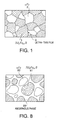
- ultra-thin films 3 containing a large amount of the nonmagnetic metallic element(s) along with Fe and B are formed at each of the crystal grain boundaries in the two-phase metallographic structure consisting of a Nd 2 Fe 14 B phase 1 and an ⁇ -Fe phase 2.
- ultra-thin films 3 contain ⁇ -Fe and thus exhibit soft magnetic properties, and moreover bring about an exchange interaction (spring effect) which produces resistance to external magnetization, leading to an improvement in coercivity. If these ultra-thin films 3 were not present, then the resistance to external magnetization would be weak and the coercivity would merely be an average of the coercivity of the Nd 2 Fe 14 B phase 1 and the ⁇ -Fe phase 2. In order to make the most of the exchange interaction, it is preferable for the ultra-thin films 3 to be as thin as possible, specifically 10 to 20 angstroms, preferably around 15 angstroms. The amount added of the nonmagnetic metallic element(s) is thus stipulated to be 0.2 to 1.3 at%, preferably around 0.5 to 1 at%.
- the alloy for a high-performance rare earth permanent magnet of the present application is made to have an approximately two-phase metallographic structure that comprises a Nd 2 Fe 14 B phase 1 and an ⁇ -Fe phase 2, with ultra-thin films 3 at each of the crystal grain boundaries between the two phases, wherein the ultra-thin films 3 have a thickness of 10 to 20 angstroms - preferably around 15 angstroms - and contain a large amount of one or more nonmagnetic metallic elements selected from the group consisting of Nb, Zr, Ta and Hf, and wherein the sizes of the crystal grains in each of the two phases are 5 to 100nm, preferably 10 to 40nm.
- the alloy for a high-performance rare earth permanent magnet of the present application comprises a Nd 2 Fe 14 B phase 1 consisting of hard magnetic crystal grains and an ⁇ -Fe phase 2 consisting of soft magnetic crystal grains, wherein the component proportions in the alloy are made to be: 6.125 to 11.6(not including 11.6) at% of Nd; a total of 0.2 to 1.3 at% of one or more nonmagnetic metallic elements selected from among Nb, Zr, Ta and Hf, preferably Nb only; a total of 4.0 to 5.8(not including 5.8) at% of B and C, with the amount of C being 0 to 0.5 at%, preferably B only; and the remainder Fe; wherein the component ratio of Nd to B is in the range 1.75:1 to 2.25:1, preferably 2:1; and wherein the sizes of the crystal grains in each of the phases are 5 to 100nm, preferably 10 to 40nm.
- the metallographic structure becomes an almost completely two-phase structure comprising a Nd 2 Fe 14 B phase having a high coercivity and an ⁇ -Fe phase having a high saturation magnetic flux, with the Nd 2 Fe 14 B phase crystal grains and the ⁇ -Fe phase crystal grains being in close proximity to one another, meaning that the exchange interaction between the phases can be brought into more-or-less full play.
- the coercivity can be made virtually as high as possible while continuing to utilize the good magnetization properties of the ⁇ -Fe phase, and so an alloy for a high-performance rare earth permanent magnet having excellent magnetic properties can be obtained.
- ultra-thin films containing a large amount of the nonmagnetic metallic element(s) are formed at each of the crystal grain boundaries between the Nd 2 Fe 14 B phase and the ⁇ -Fe phase, meaning that the coercivity is raised still further.
- the area of contact between the two phases is increased, meaning that the coercivity is raised even further.
- the alloy of the present invention is an Nd-Fe-Nb-B alloy and does not contain Co.
- the conventional alloy disclosed in Japanese Patent Application Laid-open No. 11-288807 is an Nd-Fe-Co-M-B alloy, having Co as an essential component.
- the raw material cost of Co is about the same as that of Nd, being high at about 10 times or more the raw material cost of Fe, Nb or the like.
- Such a conventional Nd-Fe-Co-M-B alloy is thus expensive. Because the alloy of the present invention does not contain Co, the production cost is lower than that of a conventional Nd-Fe-Co-M-B alloy.
- an alloy raw material is obtained by weighing out raw materials for each of the component elements so that the proportions are as follows: 6.125 to 11.6(not including 11.6) at% of Nd; a total of 0.2 to 1.3 at% of one or more nonmagnetic metallic elements selected from among Nb, Zr, Ta and Hf, preferably Nb only; a total of 4.0 to 5.8(not including 5.8) at% of B and C, with the amount of C being 0 to 0.5 at%, preferably B only; and the remainder Fe; wherein the component ratio of Nd to B is in the range 1.75:1 to 2.25:1, preferably 2:1.
- this alloy raw material is heated, thus producing a molten alloy.
- Droplets of the molten alloy are then produced using an inert gas (for example Ar gas) or the like, and these droplets are made to collide with a rotating cooling body, whereupon the droplets are quenched at a rate of at least 10 4 °C/sec, forming a ribbon-like quenching-solidified alloy body.
- an inert gas for example Ar gas
- the quenching-solidified alloy body is then subjected to heat treatment for at least 13 minutes, preferably at least 15 minutes, at a temperature of 640 to 750°C, preferably 650 to 740°C, more preferably 660 to 730°C.
- an alloy body having an approximately two-phase metallographic structure comprising a Nd 2 Fe 14 B phase and an ⁇ -Fe phase is obtained, with the sizes of the crystals in each of the phases being 5 to 100nm, preferably 10 to 40nm.
- ultra-thin films are formed at each of the crystal grain boundaries between the two phases in the alloy body, wherein these ultra-thin films have a thickness of 10 to 20 angstroms - preferably around 15 angstroms - and contain a large amount of the nonmagnetic metallic element(s).
- the alloy body obtained is pulverized as appropriate.
- the powder thus obtained can be mixed with a resin, thus obtaining a bonded magnet.
- the powder can be subjected to hot pressing, thus obtaining a bulked material.
- an anisotropic bulked material can be obtained from the powder by using a die upset method.
- a rapid quenching method conventionally used in industry can be used.
- a ribbon-like quenching-solidified body having an amorphous structure of the above-mentioned composition can be obtained, or by controlling the cooling rate, minute ⁇ -Fe crystals can be made to form within the structure.
- the ribbon-like quenching-solidified body is subsequently subjected to heat treatment, thus obtaining a two-phase structure comprising a Nd 2 Fe 14 B phase and an ⁇ -Fe phase.
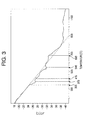
- Fig. 3 Differential thermal analysis was performed on a ribbon-like quenching-solidified body so obtained. The results are shown in Fig. 3.
- the vertical axis shows the differential temperature ⁇ T (°C)
- the horizontal axis shows the heating temperature (°C).
- the ribbon-like quenching-solidified body of the above-mentioned composition has a Curie point at about 373°C, exhibits a crystallization reaction at about 546°C, and exhibits a phase transformation (in which the Nd 2 Fe 14 B phase and the ⁇ -Fe phase are produced) at about 693°C. It can thus be inferred that the heat treatment temperature should preferably be around 693°C.
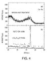
- Fig. 4(a) shows the X-ray diffraction pattern of the quenching-solidified body before heat treatment
- Fig. 4(b) shows the X-ray diffraction pattern of the quenching-solidified body after carrying out heat treatment at 700°C for 15 minutes.
- the vertical axis shows the intensity (cps)
- the horizontal axis shows 2 ⁇ (deg), where ⁇ is the angle of incidence.
- a broad diffraction pattern is obtained for the quenching-solidified body before heat treatment, from which it can be inferred that the quenching-solidified body before heat treatment has an amorphous single-phase structure.
- Fig. 4(b) on the other hand, that the diffraction pattern for the quenching-solidified body after heat treatment at 700°C for 15 minutes has a strong peak corresponding to ⁇ -Fe and is otherwise more-or-less flat, from which it can be inferred that the structure has become a two-phase structure comprising a Nd 2 Fe 14 B phase and an ⁇ -Fe phase. This verifies that a phase transformation from an amorphous structure to a two-phase structure comprising a Nd 2 Fe 14 B phase and an ⁇ -Fe phase takes place upon carrying out heat treatment at 700°C for 15 minutes.
- the cooling rate of the molten alloy, and the temperature and time of the heat treatment to which the quenching-solidified body obtained through this cooling is subjected are stipulated to be in the above-mentioned ranges.
- an alloy having an almost completely two-phase metallographic structure comprising a Nd 2 Fe 14 B phase and an ⁇ -Fe phase, and having ultra-thin films containing a large amount of the above-mentioned nonmagnetic metallic element(s) at each of the crystal grain boundaries between the two phases can be reliably obtained, and moreover the sizes of the crystals in the two phases of the alloy are of the order of a few tens of nanometer.
- Nd, Fe, Nb and Fe-B were used as raw materials, with these raw materials being weighed out such that the alloy composition would become Nd 9 Fe 85.5 Nb 1.0 B 4.5 .
- Arc melting of the raw materials was then carried out in an argon gas atmosphere, and an ingot of diameter 8 to 12mm and length 50 to 200mm was cast.
- This ingot 60 was then placed in a quartz nozzle 62 (outside diameter 12mm, bore diameter at nozzle tip 0.3 to 0.6mm) of a melt spinning machine 61, as shown in Fig. 6.
- the nozzle tip of the quartz nozzle 62 was placed into the internal hole of a carbon ring 64.
- a high frequency coil 63 running around the quartz nozzle 62 and the carbon ring 64 was provided at the bottom of the quartz nozzle 62.
- the quartz nozzle 62 was then heated using the high frequency coil 63, and at 1400°C the ingot 60 melted.
- the resulting molten alloy was squirted out of the tip of the quartz nozzle 62 using Ar gas 65 at an ejecting pressure of 1.2 ⁇ 10 5 to 2.0 ⁇ 10 5 Pa, thus producing droplets of the molten alloy.
- these droplets were made to collide with the surface of a copper roller 66 of outside diameter 250mm rotating at a peripheral speed of 15m/sec, whereupon the droplets were quenched and solidified. In this way, a ribbon-like quenching-solidified body of thickness approximately 30 ⁇ m was obtained.
- Quenching-solidified bodies produced in this way were kept at a prescribed temperature (600°C for Sample 1, 650°C for Sample 2, 700°C for Sample 3, 750°C for Sample 4, and 800°C for Sample 5) for 15 minutes in a vacuum furnace at a reduced pressure of 5.0 ⁇ 10 -3 to 1.0 ⁇ 10 -4 Pa and then cooled to room temperature, thus producing Samples 1 to 5 shown in Table 1.
- Magnetic properties were then evaluated for each sample using a VSM (vibrating sample magnetometer).
- the magnetic properties evaluated were the saturation magnetic flux density (J s ) the residual magnetic flux density (J r ), the coercivity ( J H C ) and the maximum magnetic energy product (BH) max .
- the results are shown in Table 1.
- the temperature range for the heat treatment should be 640 to 750°C, preferably 650 to 740°C, more preferably 660 to 730°C, that the magnetic properties are best when the heat treatment is carried out at around 700°C, and that there is a strikingly large drop in the magnetic properties when the heat treatment is carried out at a temperature below 640°C, while the magnetic properties also drop out of an acceptable range when the heat treatment is carried out at a temperature above 750°C.
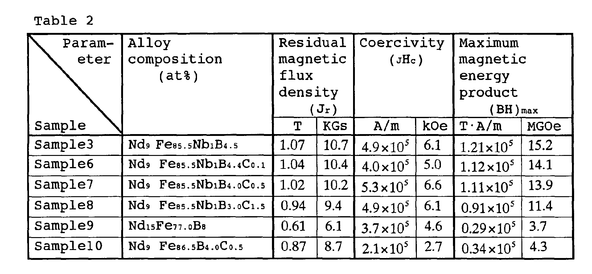
- Nd, Fe, Nb, Fe-B and Fe-C were used as raw materials, with these raw materials being weighed out such that the alloy composition would become Nd 9 Fe 85.5 Nb 1.0 B 4.5 , Nd 9 Fe 85.5 Nb 1.0 B 4.4 C 0.1 , Nd 9 Fe 85.5 Nb 1.0 B 4.0 C 0.5 , Nd 9 Fe 85.5 Nb 1.0 B 3.0 C 1.5 , Nd 15 Fe 77 B 8.0 or Nd 9 Fe 86.5 B 4.0 C 0.5 . Ribbon-like quenching-solidified bodies of thickness approximately 30 ⁇ m were then produced for each of these 6 compositions using the same method as for Example 1.
- the quenching-solidified bodies were kept at 700°C for 15 minutes in a vacuum furnace at a reduced pressure of 5.0 ⁇ 10 -3 to 1.0 ⁇ 10 -4 Pa and then cooled to room temperature, thus producing Samples 3 and 6 to 10 shown in Table 2.
- Magnetic properties were then evaluated for each sample using a VSM (vibrating sample magnetometer).
- the magnetic properties evaluated were the residual magnetic flux density (J r ), the coercivity ( J H C ) and the maximum magnetic energy product (BH) max .
- the results are shown in Table 2.
- the coercivity is good, but the other magnetic properties are slightly poorer than with Samples 3, 6 and 7, with the residual magnetic flux density being 0.94T (9.4KGs) and the maximum magnetic energy product being approximately 0.91 ⁇ 10 5 T ⁇ A/m (11.4 MGOe).
- the C content it is preferable for the C content to be no more than 0.5 at%, and hence that the Nd:B ratio may be stipulated to be in the range 2:1 to 2.25:1. It has thus been assumed that the Nd:B ratio may be up to 0.25 away from a central value of 2, and so the Nd:B ratio has been stipulated to be in the range 1.75:1 to 2.25:1.
- Sample 9 has the lowest maximum magnetic energy product out of Samples 3 and 6 to 10. This is because Sample 9 is a conventional Nd-Fe-B alloy, having a Nd-rich composition that does not fall within the compositional range for the alloy for a high-performance rare earth permanent magnet of the present application, and moreover not having a fourth element added. In other words, it is because the metallographic structure of Sample 9 is not an ⁇ -Fe + Nd 2 Fe 14 B two-phase (or approximately two-phase) structure like the other Samples, but rather an ⁇ -Fe + Nd 2 Fe 17 + Nd 2 Fe 14 B completely three-phase structure.
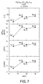
- Nd, Fe, Nb, Fe-B and Fe-C were used as raw materials, with these raw materials being weighed out such that the alloy composition would become Nd 9 Fe 85.5 Nb 1.0 B 4.0 C 0.5 .
- Four ribbon-like quenching-solidified bodies of thickness approximately 30 ⁇ m were then produced using the same method as for Example 1.
- the magnetic properties evaluated were the ratio of the residual magnetic flux density to the saturation magnetic flux density (J r /J s ), the maximum magnetic energy product (BH) max , the residual magnetic flux density (J r ) and the coercivity ( J H C ). The results are shown in Fig. 7.
- embodiments of the present invention are not limited to the above. Moreover, it goes without saying that, in addition to automobile retarders, motors and generators, the present invention can also be applied to various other equipment for which a high-performance magnet having excellent magnetic properties is required.
Landscapes
- Chemical & Material Sciences (AREA)
- Engineering & Computer Science (AREA)
- Crystallography & Structural Chemistry (AREA)
- Inorganic Chemistry (AREA)
- Power Engineering (AREA)
- Mechanical Engineering (AREA)
- Materials Engineering (AREA)
- Metallurgy (AREA)
- Organic Chemistry (AREA)
- Nanotechnology (AREA)
- Thermal Sciences (AREA)
- Physics & Mathematics (AREA)
- Composite Materials (AREA)
- Hard Magnetic Materials (AREA)
- Manufacturing Cores, Coils, And Magnets (AREA)
Abstract
Description

Nd9Fe85.5Nb1.0B4.0C0.5, Nd9Fe85.5Nb1.0B3.0C1.5, Nd15Fe77B8.0 or
Nd9Fe86.5B4.0C0.5. Ribbon-like quenching-solidified bodies of thickness approximately 30µm were then produced for each of these 6 compositions using the same method as for Example 1.
Claims (17)
- An alloy for a high-performance rare earth permanent magnet, wherein said alloy has a metallographic structure of approximately two phases that comprises a Nd2Fe14B phase consisting of hard magnetic crystal grains and an α-Fe phase consisting of soft magnetic crystal grains, and wherein said metallographic structure has an ultra-thin film that contains a large amount of nonmagnetic metallic elements that have an atomic radius of between the atomic radius of Fe and the atomic radius of Nd, and are difficult to form solid solutions with either Fe or Nd, at each of the crystal grain boundaries between said phases.
- The alloy for a high-performance rare earth permanent magnet according to claim 1, characterized in that said nonmagnetic metallic elements consist of one or two or more elements selected from among Nb, Zr, Ta and Hf, and the thickness of each of said ultra-thin films that contain a large amount of said nonmagnetic metallic elements is 10 to 20 angstroms.
- The alloy for a high-performance rare earth permanent magnet according to claim 1, characterized in that the sizes of the crystal grains in each of said phases are in the range 5 to 100nm, preferably 10 to 40nm.
- The alloy for a high-performance rare earth permanent magnet according to claim 2, characterized in that the sizes of the crystal grains in each of said phases are in the range 5 to 100nm, preferably 10 to 40nm.
- An alloy for a high-performance rare earth permanent magnet, comprising a Nd2Fe14B phase consisting of hard magnetic crystal grains and an α-Fe phase consisting of soft magnetic crystal grains, wherein the component proportions of said alloy are:6.125 to 11.6 (not including 11.6) at% of Nd;a total of 0.2 to 1.3 at% of one or more nonmagnetic metallic elements selected from among Nb, Zr, Ta and Hf;a total of 4.0 to 5.8 (not including 5.8) at% of B and C, with the amount of C being 0 to 0.5 at%; andthe remainder Fe;and the component ratio of said Nd to said B is in the range 1.75:1 to 2.25:1.
- The alloy for a high-performance rare earth permanent magnet according to claim 5, characterized in that the sizes of the crystal grains in each of said phases are in the range 5 to 100nm, preferably 10 to 40nm.
- The alloy for a high-performance rare earth permanent magnet according to claim 5, characterized in that said nonmagnetic metallic elements consist of Nb only.
- The alloy for a high-performance rare earth permanent magnet according to claim 6, characterized in that said nonmagnetic metallic elements consist of Nb only.
- An alloy for a high-performance rare earth permanent magnet, comprising a Nd2Fe14B phase consisting of hard magnetic crystal grains and an α-Fe phase consisting of soft magnetic crystal grains, wherein the component proportions of said alloy are:7.0 to 11.6 (not including 11.6) at% of Nd;0.50 to 1.00 at% of Nb;4.0 to 5.8 (not including 5.8) at% of B; andthe remainder Fe;and wherein the component ratio of said Nd to said B is 2:1, and the sizes of the crystal grains in each of said phases are in the range 5 to 100nm, preferably 10 to 40nm.
- A method of manufacturing an alloy for a high-performance rare earth permanent magnet, comprising a Nd2Fe14B phase consisting of hard magnetic crystal grains and an α-Fe phase consisting of soft magnetic crystal grains, comprising the steps of:
preparing a molten alloy, in which the component proportions are:6.125 to 11.6 (not including 11.6) at% of Nd;a total of 0.2 to 1.3 at% of one or more nonmagnetic metallic elements selected from among Nb, Zr, Ta and Hf;a total of 4.0 to 5.8 (not including 5.8) at% of B and C, with the amount of C being 0 to 0.5 at%; andthe remainder Fe;and the component ratio of said Nd to said B is in the range 1.75:1 to 2.25:1;then, quenching said molten alloy at a rate of at least 104°C/sec to form a quenching-solidified alloy body; andthen, subjecting said quenching-solidified alloy body to heat treatment for at least 13 minutes, preferably at least 15 minutes, at a temperature of 640 to 750°C, preferably 650 to 740°C, more preferably 660 to 730°C;whereby an approximately two-phase metallographic structure comprising said Nd2Fe14B phase and said α-Fe phase is produced, and an ultra-thin film containing a large amount of said nonmagnetic metallic elements is formed at each of the crystal grain boundaries between said phases. - The method of manufacturing an alloy for a high-performance rare earth permanent magnet according to claim 10, characterized in that said heat treatment is carried out to produce a metallographic structure of approximately two phases comprising said Nd2Fe14B phase and said α-Fe phase, in which the sizes of the crystal grains in each of said phases are in the range 5 to 100nm, preferably 10 to 40nm.
- A bonded magnet, which is formed by pulverizing an ingot, into a powder, an alloy obtained through the manufacturing method according to claim 10, and then mixing said powder with a resin.
- A bonded magnet, which is formed by pulverizing an ingot, into a powder, an alloy obtained through the manufacturing method according to claim 11, and then mixing said powder with a resin.
- Abulkedmagnet, which is formed by pulverizing an ingot, into a powder, an alloy obtained through the manufacturing method according to claim 10, and then subjecting said powder to hot pressing.
- A bulked magnet, which is formed by pulverizing an ingot, into a powder, an alloy obtained through the manufacturing method according to claim 11, and then subjecting said powder to hot pressing.
- An anisotropic bulked magnet, which is formed by pulverizing an ingot, into a powder, an alloy obtained through the manufacturing method according to claim 10, and then molding said powder using a die upset method.
- An anisotropic bulked magnet, which is formed by pulverizing an ingot, into a powder, an alloy obtained through the manufacturing method according to claim 11, and then molding said powder using a die upset method.
Applications Claiming Priority (2)
| Application Number | Priority Date | Filing Date | Title |
|---|---|---|---|
| JP2000144616 | 2000-05-12 | ||
| JP2000144616A JP2001323343A (en) | 2000-05-12 | 2000-05-12 | High performance rare earth permanent magnet alloy and method for producing the same |
Publications (2)
| Publication Number | Publication Date |
|---|---|
| EP1154445A2 true EP1154445A2 (en) | 2001-11-14 |
| EP1154445A3 EP1154445A3 (en) | 2002-08-21 |
Family
ID=18651248
Family Applications (1)
| Application Number | Title | Priority Date | Filing Date |
|---|---|---|---|
| EP01111584A Withdrawn EP1154445A3 (en) | 2000-05-12 | 2001-05-11 | Alloy for high-performance rare earth permanent magnet and manufacturing method thereof |
Country Status (3)
| Country | Link |
|---|---|
| US (1) | US20020003006A1 (en) |
| EP (1) | EP1154445A3 (en) |
| JP (1) | JP2001323343A (en) |
Cited By (3)
| Publication number | Priority date | Publication date | Assignee | Title |
|---|---|---|---|---|
| WO2003067081A1 (en) * | 2002-02-02 | 2003-08-14 | David Hyman Gordon | Roof mounted wind turbine |
| EP1884574A1 (en) * | 2003-03-27 | 2008-02-06 | TDK Corporation | R-T-B system rare earth permanent magnet |
| CN107077935A (en) * | 2014-12-08 | 2017-08-18 | Lg电子株式会社 | The magnet and its manufacture method of hot compression deformation comprising nonmagnetic alloy |
Families Citing this family (16)
| Publication number | Priority date | Publication date | Assignee | Title |
|---|---|---|---|---|
| US6605162B2 (en) * | 2000-08-11 | 2003-08-12 | Nissan Motor Co., Ltd. | Anisotropic magnet and process of producing the same |
| US7018487B2 (en) * | 2001-11-22 | 2006-03-28 | Nissan Motor Co., Ltd. | Magnet containing low rare earth element and method for manufacturing the same |
| US7255751B2 (en) * | 2002-09-30 | 2007-08-14 | Tdk Corporation | Method for manufacturing R-T-B system rare earth permanent magnet |
| US7311788B2 (en) * | 2002-09-30 | 2007-12-25 | Tdk Corporation | R-T-B system rare earth permanent magnet |
| US7314531B2 (en) * | 2003-03-28 | 2008-01-01 | Tdk Corporation | R-T-B system rare earth permanent magnet |
| US20050001499A1 (en) * | 2003-07-01 | 2005-01-06 | Litton Systems, Inc. | Permanent magnet rotor for brushless D.C. motor |
| CN100590757C (en) * | 2004-12-16 | 2010-02-17 | 日立金属株式会社 | Iron-based rare earth nanocomposite magnet and method for producing same |
| JP2007201102A (en) * | 2006-01-25 | 2007-08-09 | Neomax Co Ltd | Iron-based rare earth permanent magnet and method for producing the same |
| JP2008228385A (en) * | 2007-03-09 | 2008-09-25 | Keihin Corp | DRIVE MOTOR USED FOR VARIABLE VALVE CONTROL DEVICE |
| MY149353A (en) * | 2007-03-16 | 2013-08-30 | Shinetsu Chemical Co | Rare earth permanent magnet and its preparations |
| DE102009033420B4 (en) * | 2009-07-16 | 2014-07-10 | M&C Techgroup Germany Gmbh | Device for determining the oxygen content in a gas |
| JP5948033B2 (en) * | 2011-09-21 | 2016-07-06 | 株式会社日立製作所 | Sintered magnet |
| DE112012005566T8 (en) | 2012-01-04 | 2014-11-13 | National Institute For Materials Science | Seltenerdnanoverbundmagnet |
| WO2015013585A1 (en) * | 2013-07-26 | 2015-01-29 | University Of Florida Research Foundation, Incorporated | Nanocomposite magnetic materials for magnetic devices and systems |
| EP3180141B1 (en) * | 2014-08-12 | 2018-12-05 | ABB Schweiz AG | Magnet having regions of different magnetic properties and method for forming such a magnet |
| CN118507189A (en) * | 2024-05-24 | 2024-08-16 | 安徽工业大学 | Nano composite permanent magnet material and preparation method thereof |
Family Cites Families (2)
| Publication number | Priority date | Publication date | Assignee | Title |
|---|---|---|---|---|
| US5725792A (en) * | 1996-04-10 | 1998-03-10 | Magnequench International, Inc. | Bonded magnet with low losses and easy saturation |
| JPH11323509A (en) * | 1998-05-15 | 1999-11-26 | Alps Electric Co Ltd | Hard magnetic alloy compacted body and method for producing the same |
-
2000
- 2000-05-12 JP JP2000144616A patent/JP2001323343A/en active Pending
-
2001
- 2001-05-08 US US09/850,762 patent/US20020003006A1/en not_active Abandoned
- 2001-05-11 EP EP01111584A patent/EP1154445A3/en not_active Withdrawn
Cited By (5)
| Publication number | Priority date | Publication date | Assignee | Title |
|---|---|---|---|---|
| WO2003067081A1 (en) * | 2002-02-02 | 2003-08-14 | David Hyman Gordon | Roof mounted wind turbine |
| US7518255B2 (en) | 2002-02-02 | 2009-04-14 | Windsave Holdings Plc | Roof mounted wind turbine |
| EP1884574A1 (en) * | 2003-03-27 | 2008-02-06 | TDK Corporation | R-T-B system rare earth permanent magnet |
| CN107077935A (en) * | 2014-12-08 | 2017-08-18 | Lg电子株式会社 | The magnet and its manufacture method of hot compression deformation comprising nonmagnetic alloy |
| US10950373B2 (en) | 2014-12-08 | 2021-03-16 | Lg Electronics Inc. | Hot-pressed and deformed magnet comprising nonmagnetic alloy and method for manufacturing same |
Also Published As
| Publication number | Publication date |
|---|---|
| JP2001323343A (en) | 2001-11-22 |
| EP1154445A3 (en) | 2002-08-21 |
| US20020003006A1 (en) | 2002-01-10 |
Similar Documents
| Publication | Publication Date | Title |
|---|---|---|
| EP0886284B1 (en) | Cast alloy used for production of rare earth magnet and method for producing cast alloy and magnet | |
| KR100535943B1 (en) | Iron-based rare earth alloy nanocomposite magnet and method for producing the same | |
| EP0945878A1 (en) | Permanent magnets and methods for their production | |
| US20020003006A1 (en) | Alloy for high-performance rare earth permanent magnet and manufacturing method thereof | |
| US5750044A (en) | Magnet and bonded magnet | |
| US6261385B1 (en) | Magnetically anisotropic rare earth-based nanocomposite permanent magnet | |
| JPS609852A (en) | High energy stored rare earth-iron magnetic alloy | |
| JP3267133B2 (en) | Alloy for rare earth magnet, method for producing the same, and method for producing permanent magnet | |
| JP4055709B2 (en) | Manufacturing method of nanocomposite magnet by atomizing method | |
| JP7646786B2 (en) | Anisotropic rare earth sintered magnet and its manufacturing method | |
| WO2004015723A2 (en) | Nanocrystalline and nanocomposite rare earth permanent magnet materials and method of making the same | |
| EP0860838B1 (en) | Hard magnetic alloy, hard magnetic alloy compact, and method for producing the same | |
| JP3715573B2 (en) | Magnet material and manufacturing method thereof | |
| JP7684371B2 (en) | Anisotropic rare earth sintered magnet and its manufacturing method | |
| JP3264664B1 (en) | Permanent magnet having a plurality of ferromagnetic phases and manufacturing method thereof | |
| EP0924716B1 (en) | Rare earth-based permanent magnet material and method for the preparation thereof | |
| JP2008192903A (en) | Iron-based rare- earth alloy magnet | |
| JP2898229B2 (en) | Magnet, manufacturing method thereof, and bonded magnet | |
| JP3411663B2 (en) | Permanent magnet alloy, permanent magnet alloy powder and method for producing the same | |
| JP3763774B2 (en) | Quenched alloy for iron-based rare earth alloy magnet and method for producing iron-based rare earth alloy magnet | |
| JP2000003808A (en) | Hard magnetic material | |
| JP7684255B2 (en) | Anisotropic rare earth sintered magnet and its manufacturing method | |
| JP3777225B2 (en) | Isotropic permanent magnet powder having high magnetic flux density and method for producing the same | |
| JPH10312918A (en) | Magnets and bonded magnets | |
| JP4644986B2 (en) | Anisotropic iron-based permanent magnet and method for producing the same |
Legal Events
| Date | Code | Title | Description |
|---|---|---|---|
| PUAI | Public reference made under article 153(3) epc to a published international application that has entered the european phase |
Free format text: ORIGINAL CODE: 0009012 |
|
| AK | Designated contracting states |
Kind code of ref document: A2 Designated state(s): AT BE CH CY DE DK ES FI FR GB GR IE IT LI LU MC NL PT SE TR |
|
| AX | Request for extension of the european patent |
Free format text: AL;LT;LV;MK;RO;SI |
|
| PUAL | Search report despatched |
Free format text: ORIGINAL CODE: 0009013 |
|
| AK | Designated contracting states |
Kind code of ref document: A3 Designated state(s): AT BE CH CY DE DK ES FI FR GB GR IE IT LI LU MC NL PT SE TR |
|
| AX | Request for extension of the european patent |
Free format text: AL;LT;LV;MK;RO;SI |
|
| 17P | Request for examination filed |
Effective date: 20030108 |
|
| AKX | Designation fees paid |
Designated state(s): AT BE CH LI |
|
| RBV | Designated contracting states (corrected) |
Designated state(s): DE FR GB |
|
| REG | Reference to a national code |
Ref country code: DE Ref legal event code: 8566 |
|
| STAA | Information on the status of an ep patent application or granted ep patent |
Free format text: STATUS: THE APPLICATION HAS BEEN WITHDRAWN |
|
| 17Q | First examination report despatched |
Effective date: 20050415 |
|
| 18W | Application withdrawn |
Effective date: 20050513 |