EP1154429A2 - Playback and adaptive equalizing - Google Patents
Playback and adaptive equalizing Download PDFInfo
- Publication number
- EP1154429A2 EP1154429A2 EP01303843A EP01303843A EP1154429A2 EP 1154429 A2 EP1154429 A2 EP 1154429A2 EP 01303843 A EP01303843 A EP 01303843A EP 01303843 A EP01303843 A EP 01303843A EP 1154429 A2 EP1154429 A2 EP 1154429A2
- Authority
- EP
- European Patent Office
- Prior art keywords
- playback
- signal
- weighting
- playback signal
- equalizing circuit
- Prior art date
- Legal status (The legal status is an assumption and is not a legal conclusion. Google has not performed a legal analysis and makes no representation as to the accuracy of the status listed.)
- Ceased
Links
Images




Classifications
-
- H—ELECTRICITY
- H04—ELECTRIC COMMUNICATION TECHNIQUE
- H04L—TRANSMISSION OF DIGITAL INFORMATION, e.g. TELEGRAPHIC COMMUNICATION
- H04L27/00—Modulated-carrier systems
- H04L27/01—Equalisers
-
- G—PHYSICS
- G11—INFORMATION STORAGE
- G11B—INFORMATION STORAGE BASED ON RELATIVE MOVEMENT BETWEEN RECORD CARRIER AND TRANSDUCER
- G11B20/00—Signal processing not specific to the method of recording or reproducing; Circuits therefor
- G11B20/10—Digital recording or reproducing
- G11B20/14—Digital recording or reproducing using self-clocking codes
-
- G—PHYSICS
- G11—INFORMATION STORAGE
- G11B—INFORMATION STORAGE BASED ON RELATIVE MOVEMENT BETWEEN RECORD CARRIER AND TRANSDUCER
- G11B20/00—Signal processing not specific to the method of recording or reproducing; Circuits therefor
- G11B20/10—Digital recording or reproducing
- G11B20/10009—Improvement or modification of read or write signals
-
- G—PHYSICS
- G11—INFORMATION STORAGE
- G11B—INFORMATION STORAGE BASED ON RELATIVE MOVEMENT BETWEEN RECORD CARRIER AND TRANSDUCER
- G11B5/00—Recording by magnetisation or demagnetisation of a record carrier; Reproducing by magnetic means; Record carriers therefor
- G11B5/008—Recording on, or reproducing or erasing from, magnetic tapes, sheets, e.g. cards, or wires
- G11B5/00813—Recording on, or reproducing or erasing from, magnetic tapes, sheets, e.g. cards, or wires magnetic tapes
- G11B5/00847—Recording on, or reproducing or erasing from, magnetic tapes, sheets, e.g. cards, or wires magnetic tapes on transverse tracks
- G11B5/0086—Recording on, or reproducing or erasing from, magnetic tapes, sheets, e.g. cards, or wires magnetic tapes on transverse tracks using cyclically driven heads providing segmented tracks
-
- G—PHYSICS
- G11—INFORMATION STORAGE
- G11B—INFORMATION STORAGE BASED ON RELATIVE MOVEMENT BETWEEN RECORD CARRIER AND TRANSDUCER
- G11B5/00—Recording by magnetisation or demagnetisation of a record carrier; Reproducing by magnetic means; Record carriers therefor
- G11B5/02—Recording, reproducing, or erasing methods; Read, write or erase circuits therefor
- G11B5/027—Analogue recording
- G11B5/035—Equalising
-
- G—PHYSICS
- G11—INFORMATION STORAGE
- G11B—INFORMATION STORAGE BASED ON RELATIVE MOVEMENT BETWEEN RECORD CARRIER AND TRANSDUCER
- G11B5/00—Recording by magnetisation or demagnetisation of a record carrier; Reproducing by magnetic means; Record carriers therefor
- G11B5/02—Recording, reproducing, or erasing methods; Read, write or erase circuits therefor
- G11B5/09—Digital recording
-
- H—ELECTRICITY
- H03—ELECTRONIC CIRCUITRY
- H03H—IMPEDANCE NETWORKS, e.g. RESONANT CIRCUITS; RESONATORS
- H03H21/00—Adaptive networks
- H03H21/0012—Digital adaptive filters
Definitions
- the present invention relates to an apparatus and method for extracting a signal from a recording medium, and to an adaptive equalizing circuit.
- An embodiment of the present invention relates to a playback apparatus and an adaptive equalizing circuit which are suitably used for playing back, for example, a digital signal.
- An embodiment of the present invention is designed to prevent a malfunction from occurring in an adaptive equalizing circuit when a playback signal is extracted from a recording medium without performing tracking control.
- an adaptive equalizing circuit for estimating the impulse response of a transmission line in order to perform the equalization of a playback signal is used. That is, in such an adaptive equalizing circuit, as shown in, for example, Fig. 3, a playback signal supplied to an input terminal 40 is supplied to a plurality of unit delay means 41 to 44 which are connected in series.
- unit delay means 41 to 44 are formed of four stages for the sake of simplicity, in an actual apparatus, 10 or more stages of unit delay means are used.
- the signals at the input and output ends of these unit delay means 41 to 44 are supplied to weighting means 45 to 49, respectively.
- a playback signal supplied to the input terminal 40 is supplied to a computation circuit 50, whereby weighting coefficients C 1 to C 5 , for which impulse responses of a transmission line are estimated by using, for example, an LMS (Least Mean Square) algorithm, are determined. Then, the coefficients C 1 to C 5 determined by this computation circuit 50 are supplied to the weighting means 45 to 49, whereby each weighting is performed on the signals from the unit delay means 41 to 44. In addition, as a result of the signals from the weighting means 45 to 49 being added by an adder 51, the equalization of the playback signal is performed, and the equalized signal is extracted from an output terminal 52.
- LMS Least Mean Square
- means has been contrived for adding an address, for example, in recording units so as to perform recording, for repeatedly playing back the recording tracks thereof two or more times each so as to extract only normally played-back recording units, and for reconstructing the playback signal in accordance with the address, thereby extracting the playback signal without performing tracking control, for example, during playback. Accordingly, the construction for tracking control and the necessity of pre-recording a control signal on a recording medium for the control are not necessary, and it is possible to record and play back a digital signal with a simple construction.
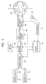
- analog signals from a video and audio signal source 61 are converted into digital signals by an analog-to-digital converter (ADC) 62 and are supplied to a compression/decompression circuit 63.
- ADC analog-to-digital converter
- a desired compression of the supplied signal is performed by the compression/decompression circuit 63, a buffer controller 64, and a buffer memory 65.
- this compressed signal is supplied to an error-correction code (ECC) modulation/demodulation section 66, and the modulated signal is supplied to magnetic heads Ha and Hb provided on a rotary drum 68 through a recording/playback circuit 67.
- ECC error-correction code
- a system controller 70 for controlling the entire apparatus is provided so that each of the above-described compression/decompression circuit 63, buffer controller 64, ECC modulation/demodulation section 66, recording/playback circuit 67, etc., is controlled according to the situation. Furthermore, communication is performed between this system controller 70 and a mechanical controller 71, so that driving means 72, such as a motor (M), for transporting, for example, a magnetic tape 69, is controlled. As a result, a signal from the recording/playback circuit 67 is recorded so as to form oblique tracks on the magnetic tape 69 which is transported around the peripheral surface of the rotary drum 68.
- driving means 72 such as a motor (M)
- the azimuth angles of the respective magnetic gaps thereof are different in mutually opposite directions from the angle intersecting at right angles to the direction of the rotation of the rotary drum 68, and the magnetic head Hb is arranged so as to perform recording at a position overlapping a portion of the track recorded by the magnetic head Ha.
- a track pattern such as that shown in, for example, Fig. 5A is formed on the magnetic tape 69 transported around the peripheral surface of the rotary drum 68. That is, in Fig. 5A, recording and playback, in which what is commonly called “guard bands" between tracks are eliminated, are performed.
- the azimuth angles of the respective magnetic gaps thereof are different in mutually opposite directions from the angle intersecting at right angles to the direction of the rotation of the rotary drum 68, the magnetic head Ha performs recording of the next track at a position two track pitches after the previously recorded track, and the magnetic head Hb is arranged to perform recording at a position which is one track pitch before the next track recorded by the magnetic head Ha.
- a track pattern such as that shown in, for example, Fig. 5B is formed on the magnetic tape 69 transported around the peripheral surface of the rotary drum 68.
- Figs. 5A and 5B first, recording of recording tracks Ta1, Ta2, ... is performed every other track by the magnetic head Ha having a large width, and thereafter, recording tracks Tb1, Tb2, ... are recorded in the boundary portions between these recorded tracks by the magnetic head Hb.
- the spacing between the recording tracks Ta1 and Tb1, and between Tb1 and Ta2 is always maintained at a fixed spacing, and a specified track pattern is formed on the magnetic tape 69.
- recording is performed, for example, for each track for one rotation of the rotary drum 68 alternately by the magnetic heads Ha and Hb.
- playback is performed in units of two tracks for each rotation of the rotary drum 68, for example, by the magnetic heads Hc and Hd provided on the rotary drum 68.
- each recording track recorded by the magnetic heads Ha and Hb is played back two times each by each of the magnetic heads Hc and Hd.
- the magnetic heads Ha and Hb are provided at a relative angle of 45 degrees with respect to the circumference of the rotary drum 68, and the magnetic heads Hc and Hd are provided at a relative angle of 180 degrees.
- the recording/playback circuit 67 supplying of a signal and extraction of a signal are performed, as shown in, for example, Fig. 6. That is, for one rotation of the rotary drum 68 shown in part (a) of Fig. 6, at the time of recording, recording is performed by the magnetic heads Ha and Hb, as shown in parts (b) and (c) of Fig. 6. On the other hand, at the time of playback, playback is performed by the magnetic heads Hc and Hd, as shown in parts (d) and (e) of Fig. 6. As a result, the recording tracks which are recorded in units of one track for one rotation of the rotary drum 68 are played back in units of two tracks for one rotation of the rotary drum 68.
- the recording tracks recorded by the magnetic heads Ha and Hb are played back two times for each of the magnetic heads Hc and Hd.
- an arbitrary address, etc. is provided in digital data to be recorded for each recording unit, and only the recording units which have been played back normally are extracted from the playback signal which is played back two times each, making it possible to reconstruct the digital data.
- Such reconstruction of the digital data can be performed by the cooperation of the buffer controller 64 and the buffer memory 65 at the same time as, for example, the demodulation of error correction in the ECC modulation/demodulation section 66.
- the digital data reconstructed by the modulation/demodulation section 66 is supplied to the compression/decompression circuit 63, whereby decompression for returning the data compressed during recording to the original is performed. Furthermore, the decompressed digital signal is converted into an analog signal by a digital-to-analog converter (DAC) 73, and, for example, analog signals of the video and audio signals are extracted. Then, the extracted video and audio signals are supplied to a display device 74 of a television receiver, etc. In this manner, recording and playback, for example, using digital data of the video and audio signals are performed.
- DAC digital-to-analog converter
- Embodiments of the invention described herein seek to solve the problem that, in a conventional apparatus, when continuous noise occurs frequently, erroneous weighting coefficients might be formed in an adaptive equalizing circuit, and therefore, the adaptive equalizing circuit cannot be employed in a playback apparatus which does not perform, for example, tracking control.
- an envelope value of an input signal is detected, and when this envelope value is more than or equal to a predetermined value, weighting coefficients in the adaptive equalizing circuit are changed.
- an adaptive equalizing circuit can be employed satisfactorily in a playback apparatus which does not perform, for example, tracking control.
- a playback signal extracted without performing tracking control in the manner described above, and an envelope waveform thereof were input at the same time to a personal computer, and the effects of control in a computation circuit of an adaptive equalizing circuit by envelope information were checked by simulation.
- a comparison was performed by using a value ( ⁇ DSNR: unit dB) showing how much the digital signal-to-noise ratio (DSNR) of a signal after passing through an adaptive equalizing circuit was improved with respect to the input signal in a case where a playback signal having a different envelope value (ENV) is input to the adaptive equalizing circuit.
- the results of this evaluation are shown in Table 1 with regard to four cases (cases 1 to 4) in which the envelope value is different.
- the value (ENV) in Table 1 indicates the range of the envelope values at the section used for the simulation.
- the value (normalized ENV) indicates the ratio of the value (ENV) to the maximum value (180) of the envelope of a playback signal obtained when the playback head performs playback for a corresponding recording track.
- ENV Normalized ENV ⁇ DSNR Case 1 140-160 78-89% 2.18 Case 2 120-140 67-78% 2.15 Case 3 100-120 56-67% 2.10 Case 4 65-100 36-56% 1.01
- the improved value ( ⁇ DSNR) is determined by the coefficient obtained by the computation circuit of the adaptive equalizing circuit. It is revealed from this Table 1 that an improved value ( ⁇ DSNR) at nearly the same level was obtained from the coefficient obtained as a result of a calculation by a signal (cases 1 to 3) having an envelope value (ENV) whose value (Normalized ENV) exceeds 50%, but, from the coefficient obtained as a result of a calculation by a signal (case 4) having an envelope value (ENV) whose value (Normalized ENV) falls short of 50%, the improved value ( ⁇ DSNR) becomes half or less.
- the playback signal corresponding to case 4 it is shown that the characteristics of the adaptive equalizing circuit are degraded, and that, for example, when a playback signal which is extracted without performing tracking control in the manner described above is made to pass through such an adaptive equalizing circuit, sufficient effects of the improved digital signal-to-noise ratio are not obtained.
- the present invention provides a playback apparatus and method for extracting a playback signal from a recording medium without performing tracking control, the playback apparatus comprising an adaptive equalizing circuit for performing equalization of a playback signal; and detection means for determining the envelope value of the playback signal, wherein the adaptive equalizing circuit is controlled in accordance with the envelope value from the detection means.
- the present invention provides an adaptive equalizing circuit and method for changing each weighting coefficient of a plurality of weighting means in accordance with an input signal
- the adaptive equalizing circuit comprising: a plurality of unit delay means for delaying an input signal in sequence; a plurality of weighting means for performing weighting on each of the delay signals; addition means for adding together the weighted signals; and detection means for determining an envelope value of the input signal, wherein when the envelope value from the detection means is more than or equal to a predetermined value, the coefficients in the weighting means are changed.
- Fig. 1 is a block diagram showing the construction of an embodiment of a playback apparatus according to the present invention.
- the main portions of the present embodiment are shown in detail, and the other portions are omitted.
- the construction of the other portions is the same as the construction of Fig. 4 described in the Related Art part.
- a playback signal which is played back from a magnetic tape 1 by a playback head 2 is supplied to a playback amplifier 3, and the signal from this playback amplifier 3 is supplied to an automatic gain control circuit 5 through an analog equalizing circuit 4. Then, the gain-controlled signal is supplied to an analog-to-digital converter (ADC) 6. Furthermore, the digital signal converted by this analog-to-digital converter 6 is supplied to a phase-locked loop (PLL) means 7, whereby the data clock of the playback signal is extracted, and this extracted data clock is supplied to the converter 6, whereby the digital conversion of the playback signal is performed.
- ADC analog-to-digital converter
- PLL phase-locked loop
- the signal from the playback amplifier 3 is supplied to a detector 8 for determining an envelope value, and the envelope value of the playback signal, detected by this detector 8, is supplied to the phase-locked loop (PLL) means 7 through an analog-to-digital converter (ADC) 9.
- PLL phase-locked loop
- ADC analog-to-digital converter
- the envelope value of the playback signal from the analog-to-digital converter 9 and a detection signal indicating whether or not the phase lock for the playback signal from the phase-locked loop means 7 has been performed, are supplied to the adaptive digital equalizing circuit 10. Then, in the adaptive digital equalizing circuit 10, control is performed so that, for example, only when the envelope value of the playback signal is more than or equal to 50% of the maximum value and the phase lock for the playback signal has been performed, a weighting coefficient, for which the impulse response of the transmission line is estimated by using, for example, an LMS (Least Mean Square) algorithm, is changed.
- LMS Least Mean Square
- the signal from the adaptive digital equalizing circuit 10 is supplied to a viterbi decoder 11.
- a viterbi decoder 11 by using an impulse response of each transmission line, which is estimated by a different weighting coefficient, a transmission symbol sequence in which the pass metric reaches a maximum is estimated, and a transmission symbol sequence in which the maximum value of the computed pass metric reaches a maximum is output. That is, for the output transmission symbol sequence, an optimum estimated coefficient of the LMS in the adaptive digital equalizing circuit 10 has been selected, making it possible to reduce the estimated error in order to accurately estimate the impulse response.
- the signal from the viterbi decoder 11 is supplied to, for example, an error-correction code (ECC) demodulation section 12, whereby, for example, the reconstruction of the digital data is performed at the same time as the error correction. Furthermore, this reconstructed digital data is supplied to a decompression circuit (not shown), etc., and decompression for returning the data compressed during recording to the original is performed. Then, this signal is converted into an analog signal by a digital-to-analog converter (DAC) 13, whereby, for example, analog signals of the video and audio signals are extracted from an output terminal 14. In this manner, for example, video and audio signals which are recorded digitally are read.
- ECC error-correction code
- the envelope value of the playback signal is less than or equal to 50% of the maximum value as in case 4 of the above-described Table 1, erroneous weighting is performed in the adaptive digital equalizing circuit 10.
- a threshold value of the envelope value is set, and only the playback data of an envelope waveform, which is larger than that value, is used for a coefficient computation.
- the envelope waveform depends on a playback system, a recording medium, or a recording apparatus, the value is set on the basis of the playback signal obtained under the optimum conditions obtained by the entire system at that time.
- the weighting coefficients in the adaptive digital equalizing circuit 10 are not changed.
- the reason for this is that it is known that, for example, even if the envelope value of the playback signal is more than or equal to a threshold value, unless the phase-locked loop means 7 is phase-locked, the calculation of a coefficient using such a signal causes the characteristics of the equalizing circuit to be degraded. That is, it is because, in the digital equalizing circuit, even a time-related error during a sampling cannot be corrected.
- the envelope value of the input signal is detected, and when this envelope value is more than or equal to a threshold value, the weighting coefficients in the adaptive digital equalizing circuit are changed, thereby preventing erroneous weighting from being performed also when continuous noise occurs frequently.
- an adaptive equalizing circuit can be satisfactorily employed in a playback apparatus which does not perform, for example, tracking control.
- an adaptive equalizing circuit for performing equalization of a playback signal when a playback signal is extracted from a recording medium without performing tracking control is provided, detection means for determining the envelope value of the playback signal is provided, and the adaptive equalizing circuit is controlled in accordance with the envelope value from the detection means, thereby preventing erroneous weighting from being performed even when continuous noise occurs frequently.
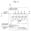
- the adaptive digital equalizing circuit 10 is constructed as shown in, for example, Fig. 2.
- a playback signal supplied to an input terminal 20 is supplied to a plurality of unit delay means 21 to 24 which are connected in series.
- the unit delay means are formed of four stages, in an actual apparatus, 10 or more stages of unit delay means are used. Then, the signals at the input ends and the output ends of these unit delay means 21 to 24 are supplied to weighting means 25 to 29, respectively.
- the playback signal supplied to the input terminal 20 is supplied to a computation circuit 30, whereby weighting coefficients C 1 to C 5 , for which an impulse response of the transmission line is estimated by using, for example, an LMS (Least Mean Square) algorithm, are determined. Then, the determined coefficients C 1 to C 5 are supplied to the weighting means 25 to 29, whereby each weighting is performed on the signals from the unit delay means 21 to 24. In addition, as a result of the signals from the weighting means 25 to 29 being added by an adder 31, the equalization of the playback signal is performed, and the equalized signal is extracted from an output terminal 32.
- LMS Least Mean Square
- the envelope value of the playback signal from the analog-to-digital converter 9, and the detection signal indicating whether or not the phase lock for the playback signal from the phase-locked loop means 7 has been performed are supplied to the computation circuit 30. Then, in this computation circuit 30, only when the envelope value of the playback signal is more than or equal to a predetermined value and the phase lock for the playback signal has been performed, the calculation of the weighting coefficients C 1 to C 5 is performed. Furthermore, control is performed so that the coefficients of the weighting means 25 to 29 are changed in accordance with the determined weighting coefficients C 1 to C 5 , respectively.
- the envelope value of the playback signal is less than or equal to 50% of the maximum value as in case 4 of the above-described Table 1, erroneous calculation is performed by the computation circuit 30.
- a threshold value of the envelope value is set, and only the playback data of an envelope waveform, which is larger than that value, is used for a coefficient computation.
- the envelope waveform depends on a playback system, a recording medium, or a recording apparatus, the value is set on the basis of the playback signal obtained under the optimum conditions obtained by the entire system at that time.
- the weighting coefficients in the adaptive digital equalizing circuit 10 are not changed.
- the reason for this is that it is known that, for example, even if the envelope value of the playback signal is more than or equal to a threshold value, unless the phase-locked loop means 7 is phase-locked, the calculation of a coefficient using such a signal causes the characteristics of the equalizing circuit to be degraded. That is, it is because, in the digital equalizing circuit, even a time-related error during sampling cannot be corrected.
- the envelope value of the input signal is detected, and when this envelope value is more than or equal to a threshold value, the weighting coefficients in the adaptive digital equalizing circuit are changed, thereby preventing erroneous weighting from being performed even when continuous noise occurs frequently.
- an adaptive equalizing circuit can be satisfactorily employed in a playback apparatus which does not perform, for example, tracking control.
- adaptive equalizing circuit for changing each weighting coefficient of a plurality of weighting means in accordance with an input signal, a plurality of unit delay means for delaying the input signal in sequence, a plurality of weighting means for performing a weighting on each of these delay signals, addition means for adding together these weighted signals, and detection means for determining the envelope value of the input signal are provided.
- the envelope value from the detection means is more than or equal to a predetermined value, the coefficients in the weighting means are changed.
Landscapes
- Engineering & Computer Science (AREA)
- Signal Processing (AREA)
- Computer Networks & Wireless Communication (AREA)
- Signal Processing For Digital Recording And Reproducing (AREA)
- Picture Signal Circuits (AREA)
- Television Signal Processing For Recording (AREA)
- Cable Transmission Systems, Equalization Of Radio And Reduction Of Echo (AREA)
- Filters That Use Time-Delay Elements (AREA)
Abstract
Description
| ENV | Normalized ENV | ΔDSNR | |
| Case 1 | 140-160 | 78-89% | 2.18 |
| | 120-140 | 67-78% | 2.15 |
| | 100-120 | 56-67% | 2.10 |
| | 65-100 | 36-56% | 1.01 |
Claims (8)
- A playback apparatus for extracting a playback signal from a recording medium without performing tracking control, said playback apparatus comprising:an adaptive equalizing circuit for performing equalization of said playback signal; anddetection means for determining an envelope value of said playback signal, wherein said adaptive equalizing circuit is controlled in accordance with an envelope value from said detection means.
- A playback apparatus according to Claim 1,
wherein said adaptive equalizing circuit comprises:a plurality of unit delay means for delaying said playback signal in sequence;a plurality of weighting means for performing weighting on each of the delay signals; andaddition means for adding together the weighted signals, andwherein each of the weighting signals of said plurality of weighting means is changed in accordance with said playback signal, and when the envelope value of said playback signal is more than or equal to a predetermined value, the coefficients in said weighting means are changed. - A playback apparatus according to Claim 2, further comprising phase-locked loop means for forming a signal locked to an arbitrary phase of said playback signal, wherein when phase lock has been performed by said phase-locked loop means, the coefficients in said weighting means are changed.
- An adaptive equalizing circuit for changing each weighting coefficient of a plurality of weighting means in accordance with an input signal, said adaptive equalizing circuit comprising:a plurality of unit delay means for delaying the input signal in sequence;the plurality of weighting means for performing weighting on each of the delay signals;addition means for adding together the weighted signals; anddetection means for determining an envelope value of said input signal, wherein when the envelope value from said detection means is more than or equal to a predetermined value, the coefficients in said weighting means are changed.
- An adaptive equalizing circuit according to Claim 4, further comprising phase-locked loop means for forming a signal locked to an arbitrary phase of said input signal, wherein when phase lock has been performed by said phase-locked loop means, the coefficients in said weighting means are changed.
- A playback method for extracting a playback signal from a recording medium without performing tracking control, said playback method comprising:a detection step for determining an envelope value of said playback signal; anda step for performing adaptive equalization on said playback signal in accordance with said envelope value.
- A playback method according to Claim 6,
wherein said step for performing adaptive equalization comprises the steps of:delaying said playback signal in sequence by a plurality of unit delay means;weighting the delayed delay signals by respective coefficients; andadding together the weighted signals, andwherein, when the envelope value of said playback signal is more than or equal to a predetermined value, said weighting step changes said weighting coefficients in accordance with said playback signal. - A playback method according to Claim 7, further comprising a step for forming a signal which is locked to an arbitrary phase of said playback signal, wherein, when phase lock has been performed in said signal forming step, said weighting coefficients are changed in accordance with said playback signal.
Applications Claiming Priority (2)
| Application Number | Priority Date | Filing Date | Title |
|---|---|---|---|
| JP2000134830 | 2000-05-08 | ||
| JP2000134830A JP2001319421A (en) | 2000-05-08 | 2000-05-08 | Playback device and adaptive equalization circuit |
Publications (2)
| Publication Number | Publication Date |
|---|---|
| EP1154429A2 true EP1154429A2 (en) | 2001-11-14 |
| EP1154429A3 EP1154429A3 (en) | 2006-08-23 |
Family
ID=18643031
Family Applications (1)
| Application Number | Title | Priority Date | Filing Date |
|---|---|---|---|
| EP01303843A Ceased EP1154429A3 (en) | 2000-05-08 | 2001-04-27 | Playback and adaptive equalizing |
Country Status (4)
| Country | Link |
|---|---|
| US (1) | US7174087B2 (en) |
| EP (1) | EP1154429A3 (en) |
| JP (1) | JP2001319421A (en) |
| KR (1) | KR100776874B1 (en) |
Families Citing this family (2)
| Publication number | Priority date | Publication date | Assignee | Title |
|---|---|---|---|---|
| TWI273801B (en) * | 2004-11-29 | 2007-02-11 | Mediatek Inc | Weighted adaptive equalizer and related method thereof |
| US10187224B2 (en) * | 2017-03-15 | 2019-01-22 | Panasonic Corporation | Radio receiving apparatus |
Family Cites Families (11)
| Publication number | Priority date | Publication date | Assignee | Title |
|---|---|---|---|---|
| US5663844A (en) * | 1990-11-19 | 1997-09-02 | Canon Kabushiki Kaisha | Signal reproducing apparatus having waveform equalizing function |
| EP0527017B1 (en) * | 1991-08-03 | 1997-03-26 | Sony Corporation | Magnetic reproducing apparatus |
| JPH06103696A (en) * | 1992-09-16 | 1994-04-15 | Hitachi Ltd | Data signal reproducing device |
| US5835666A (en) * | 1994-09-22 | 1998-11-10 | Canon Kabushiki Kaisha | Reproducing apparatus including equalizing means which equalizes a reproduced signal when the signal is between a first and second level and varies the response speed |
| JPH08180583A (en) * | 1994-12-28 | 1996-07-12 | Hitachi Ltd | Reproducing circuit of magnetic recording / reproducing device |
| GB2305828B (en) * | 1995-09-29 | 2000-06-14 | Sony Corp | Automatic equalizer and digital signal reproducing apparatus carrying the same |
| KR0184400B1 (en) * | 1996-12-30 | 1999-04-15 | 대우전자주식회사 | Adaptive equalizer |
| GB2320866A (en) * | 1996-12-30 | 1998-07-01 | Daewoo Electronics Co Ltd | An equalization arrangement in which initial values which determine tap coefficients are adaptively chosen |
| KR100223192B1 (en) * | 1997-04-02 | 1999-10-15 | 윤종용 | Vcr |
| KR100334436B1 (en) * | 1998-11-18 | 2002-10-09 | 삼성전자 주식회사 | Apparatus for reproducing data |
| JP3859386B2 (en) * | 1999-03-31 | 2006-12-20 | 三菱電機株式会社 | Waveform equalizer, waveform equalizer, and receiver |
-
2000
- 2000-05-08 JP JP2000134830A patent/JP2001319421A/en active Pending
-
2001
- 2001-04-27 EP EP01303843A patent/EP1154429A3/en not_active Ceased
- 2001-05-04 US US09/849,856 patent/US7174087B2/en not_active Expired - Fee Related
- 2001-05-07 KR KR1020010024549A patent/KR100776874B1/en not_active Expired - Fee Related
Also Published As
| Publication number | Publication date |
|---|---|
| KR100776874B1 (en) | 2007-11-16 |
| US20010053272A1 (en) | 2001-12-20 |
| KR20010102939A (en) | 2001-11-17 |
| US7174087B2 (en) | 2007-02-06 |
| JP2001319421A (en) | 2001-11-16 |
| EP1154429A3 (en) | 2006-08-23 |
Similar Documents
| Publication | Publication Date | Title |
|---|---|---|
| US8295001B2 (en) | Systems and methods for low latency noise cancellation | |
| US7733592B2 (en) | Methods for multi-channel data detection phase locked loop frequency error combination | |
| US10483999B1 (en) | Loop consistency using multiple channel estimates | |
| US20050007684A1 (en) | Data synchronizing signal detector, signal processing device using the detector, information recording and reproducing apparatus having the detector and the device, data synchronizing signal detecting method, and information recording medium for using in the method | |
| JP4190136B2 (en) | Data recording / reproducing device | |
| JP2001319433A (en) | Data playback device | |
| US5602858A (en) | Digital signal decoding apparatus having a plurality of correlation tables and a method thereof | |
| US5440572A (en) | Digital signal decoding apparatus and a method thereof having a function of initializing a pass metric for at least one compression block | |
| EP1154429A2 (en) | Playback and adaptive equalizing | |
| US7206152B2 (en) | Adaptive equalizing circuit and regenerative device using it, and adaptive equalizing method | |
| US7773326B2 (en) | Methods for multi-channel data detection phase locked loop error combination | |
| US8854757B2 (en) | Systems and methods for old data inter-track interference compensation | |
| US7773327B2 (en) | Multi-channel data detection phase locked loop frequency error combination logic | |
| US7924522B2 (en) | Apparatus and method of detecting error symbol, and disk drive apparatus using the same | |
| US11170815B1 (en) | Cancelling adjacent track interference | |
| JP2004022041A (en) | Playback device and adaptive equalization circuit | |
| US8848308B2 (en) | Systems and methods for ADC sample based inter-track interference compensation | |
| JP2770499B2 (en) | Waveform equalization circuit | |
| JP2917191B2 (en) | Digital signal reproduction device | |
| JP5579379B2 (en) | Frequency error combinational logic configured for a multi-channel data detection system and method for generating frequency errors | |
| US20160314814A1 (en) | Systems and Methods for Side-Track Aided Data Recovery | |
| JPWO1999013458A1 (en) | Magnetic recording device and magnetic recording method, magnetic reproducing device and magnetic reproducing method, and magnetic recording and reproducing device and magnetic recording and reproducing method | |
| JPH11259995A (en) | Digital playback device | |
| JPH10289530A (en) | Playback device | |
| JPH06251509A (en) | Digital signal detection circuit |
Legal Events
| Date | Code | Title | Description |
|---|---|---|---|
| PUAI | Public reference made under article 153(3) epc to a published international application that has entered the european phase |
Free format text: ORIGINAL CODE: 0009012 |
|
| AK | Designated contracting states |
Kind code of ref document: A2 Designated state(s): AT BE CH CY DE DK ES FI FR GB GR IE IT LI LU MC NL PT SE TR |
|
| AX | Request for extension of the european patent |
Free format text: AL;LT;LV;MK;RO;SI |
|
| PUAL | Search report despatched |
Free format text: ORIGINAL CODE: 0009013 |
|
| AK | Designated contracting states |
Kind code of ref document: A3 Designated state(s): AT BE CH CY DE DK ES FI FR GB GR IE IT LI LU MC NL PT SE TR |
|
| AX | Request for extension of the european patent |
Extension state: AL LT LV MK RO SI |
|
| RIC1 | Information provided on ipc code assigned before grant |
Ipc: H03H 21/00 20060101ALI20060717BHEP Ipc: G11B 5/008 20060101ALI20060717BHEP Ipc: G11B 5/09 20060101ALI20060717BHEP Ipc: G11B 20/10 20060101ALI20060717BHEP Ipc: G06F 17/30 20060101AFI20060717BHEP |
|
| 17P | Request for examination filed |
Effective date: 20070206 |
|
| AKX | Designation fees paid |
Designated state(s): DE FR GB NL |
|
| 17Q | First examination report despatched |
Effective date: 20070424 |
|
| STAA | Information on the status of an ep patent application or granted ep patent |
Free format text: STATUS: THE APPLICATION HAS BEEN REFUSED |
|
| 18R | Application refused |
Effective date: 20090412 |