EP1154388B1 - Télémetrie de messages de diagnostic provenant d'une entité mobile et à destination d'une station à distance - Google Patents
Télémetrie de messages de diagnostic provenant d'une entité mobile et à destination d'une station à distance Download PDFInfo
- Publication number
- EP1154388B1 EP1154388B1 EP01303630.6A EP01303630A EP1154388B1 EP 1154388 B1 EP1154388 B1 EP 1154388B1 EP 01303630 A EP01303630 A EP 01303630A EP 1154388 B1 EP1154388 B1 EP 1154388B1
- Authority
- EP
- European Patent Office
- Prior art keywords
- node
- aircraft
- messages
- ism
- receiver
- Prior art date
- Legal status (The legal status is an assumption and is not a legal conclusion. Google has not performed a legal analysis and makes no representation as to the accuracy of the status listed.)
- Expired - Lifetime
Links
Images


Classifications
-
- G—PHYSICS
- G08—SIGNALLING
- G08C—TRANSMISSION SYSTEMS FOR MEASURED VALUES, CONTROL OR SIMILAR SIGNALS
- G08C15/00—Arrangements characterised by the use of multiplexing for the transmission of a plurality of signals over a common path
- G08C15/06—Arrangements characterised by the use of multiplexing for the transmission of a plurality of signals over a common path successively, i.e. using time division
- G08C15/12—Arrangements characterised by the use of multiplexing for the transmission of a plurality of signals over a common path successively, i.e. using time division the signals being represented by pulse characteristics in transmission link
-
- G—PHYSICS
- G08—SIGNALLING
- G08C—TRANSMISSION SYSTEMS FOR MEASURED VALUES, CONTROL OR SIMILAR SIGNALS
- G08C17/00—Arrangements for transmitting signals characterised by the use of a wireless electrical link
- G08C17/02—Arrangements for transmitting signals characterised by the use of a wireless electrical link using a radio link
Definitions
- This invention relates generally to remote monitoring and diagnostics, and more specifically relates to telemetry of diagnostic messages from a mobile asset to a remote service center.
- One embodiment of the present invention is a telemetry system employing airborne sensors and telemeters to transmit maintenance data (such as performance data of an aircraft engine) from an aircraft-in-flight to a ground based service center.
- Remote monitoring and diagnosing of the condition, performance, and failure of parts, equipment and systems carried by mobile assets such as airplanes, turbines, locomotives and medical systems is becoming increasingly important as industry struggles to improve safety, reduce maintenance costs and deliver efficient, timely and cost effective maintenance services to its customers. For that reason, remote maintenance services are seen by today's service oriented businesses as an important growth area. Remote monitoring and diagnosing capability is quickly becoming a key element in providing high-technology, value-added services for an installed equipment base which equipment base may include mobile assets such as power generation equipment, aircraft engines, medical imaging systems, and locomotives.
- Telemetry systems for monitoring mobile assets are described in EP-A-0,292,811 , FR-A-2,693,068 , and US-A-5,065,321 .
- US-A-5,867,801 describes a vehicle tracking and monitoring system for monitoring railway cars within a defined radius of a receiver for wireless communication.
- US-A-5,742,336 describes an aircraft surveillance and recording system including a satellite relay.
- EP-A-0,748,082 describes a network of tracked mobile assets which are temporarily located in an area such as a railway yard.
- Control systems for devices such as turbines used for generation of electricity or turbines used in aircraft engines typically monitor a variety of turbine performance parameters, including speed, temperatures, and stresses on the turbine assembly. Prior art systems provide for monitoring these parameters in flight. However, many of the problems associated with relaying these parameters to a ground service center while the aircraft is in flight remain to be solved.
- a significant problem encountered in the art of wireless digital communications of performance parameters relates to the frequency and, more importantly, the power at which telemetry devices can transmit RF signals.
- FCC Federal Communications Commission
- aircraft telemetry systems were primarily limited to the VHF band (174-216 MHz), and could only operate at very low transmission powers of less than 0.1 milliwatts (mW). (See FCC Part 15.241.)
- This restriction on the transmission power has significantly limited the transmission range (i.e., the maximum distance between the transmitter and the receiver) of airborne telemetry devices.
- Restrictions also place limits on the data rate or "bandwidth" at which the telemetry devices can transmit data.
- the invention is defined by the telemetry system of independent claim 1.
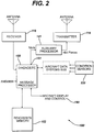
- Telemetry system 10 comprises a telemeter 100, a transmitter 118 and a remote station 200.
- Telemeter 100 is carried upon a mobile asset, such as an aircraft 20, locomotive 22 , ship 24, or the like and configured to monitor the condition of the asset upon which it is installed.
- Telemeter 100 in conjunction with transmitter 118 transmits messages, referred to herein as diagnostic messages, containing information about the condition and performance of the assets to remote station 200.
- diagnostic messages containing information about the condition and performance of the assets to remote station 200.
- condition refers to the state of readiness, or fitness for operation of an asset or of a particular component of an asset.
- Diagnostic messages are relayed directly from the asset, such as aircraft 20, being monitored (referred to herein as a source) to a remote station 200 (referred to herein as a destination). Diagnostic messages may also be relayed in series from a source asset, such as aircraft 20, to a successor asset, such as aircraft 21, and in some cases from a successor asset to another successor asset, and so on until the diagnostic message arrives at its remote station destination 200.
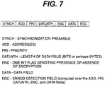
- the message format comprises a synchronization preamble, address bits, priority bits if desired, a data field, an encryption flag denoting the presence or absence of encryption of the data in the data field, and an error detection field.
- Down links 45 are communications channels comprising unlicensed, or Industrial/Scientific/Medical (ISM) band, transmissions.
- ISM Industrial/Scientific/Medical
- Three ISM bands are now available in the United States for using spread-spectrum communications techniques: 902-928 MHz; 2400-2483.5 MHz; and 5725-5850 MHz.
- transmitter 110 is adapted to transmit in an ISM frequency band.
- data links 45 further include non ISM band radio frequency channels such as those licensed by the Federal Communications Commission (FCC).
- FCC Federal Communications Commission
- Telemeter 100 is installed upon aircraft 20. Telemeter 100 monitors one or more jet engine conditions of aircraft 20 and transmits messages containing information about the performance of the aircraft between aircraft 20 and remote station 200. Remote station 200 utilizes the information contained in the messages to assess engine performance, identify and predict failure conditions, and in one example to relay corrective signals to aircraft 20 via data uplink 30 to correct or compensate for failure conditions.
- data uplink 30 comprises ISM band transmissions.
- data uplink 30 comprises commands and data in an FCC licensed radio frequency band.
- Telemeter 100 comprises as major components transmitter 118, receiver 116, diagnostic message processor 150, memory 152, display 190, condition sensors 320 and a first auxiliary processor 141.
- Condition sensors 320 monitor performance conditions and parameters such as turbine speed, and exhaust gas temperature.
- telemeter 100 is implemented using avionics equipment already in place on aircraft 20, as for example VHF, or UHF transceivers for other avionics applications licensed by the FCC for operation in RF bands.
- VHF Very High Frequency
- transmitter 118 includes an ISM modem of a type readily commercially available.
- telemeter 100 includes a low power 2.4 GHZ ISM transceiver, represented in FIG. 2 by receiver 116 and transmitter 118.
- Receiver 116 and transmitter 118 include modems employing typical direct sequence spread spectrum modulation schemes to modulate a carrier with diagnostic message information. Such schemes may be implemented in synchronous mode or in transmitted reference mode to alleviate the synchronization overhead.
- the ISM band relies on in-flight use of the 2.4 GHz ISM at 2.4GHz -2.4835 GHz.
- Commercially available chip sets such as the Harris PRISMTM chip set and a wide variety of support electronics are readily commercially available for use in this example.
- DSSS Direct Sequence Spread Spectrum
- the Harris PRISM set spreads with a factor of 11 and is programmable for up to a factor of 16, making it advantageous.
- An alternative example employs 5.7GHz band transceivers.
- an example is configured to carry out a method by which the same message is transmitted a plurality of times, the number of retransmission times based on the expected channel losses associated with the communications channel in use. This technique provides increased reliability of the link as data rates decrease.
- First diagnostic message processor 150 provides a message to be transmitted comprising N information bits to first auxiliary processor 141.
- Processor 141 is configured to encode the N information bits into B (B greater than N) message bits by means of a forward error correction code, for example, a Hamming code.
- B forward error correction code
- the B bit message is broken into portions of n-bits each. In one example any fractional piece is padded with trailing zeros or other conventional fillers.
- the greater the value of n the more efficient is the random parity coding implementation. However, greater values of n add to the complexity of the decoder. In one example n is chosen to be 12.
- auxiliary processor 141 estimates an expected bit error rate, p.
- Bit error rate p is the error rate that a ground based receiver will experience on bit by bit demodulation of an ISM transmission at the ISM modem design rate.
- p is predetermined and provided to auxiliary processor 141.
- BSC Binary Symmetric Channel
- a system parameter, ⁇ is provided to processor 141 by an operator.
- System parameter ⁇ is chosen to provide sufficient redundancy such that the N information bits are decoded with a desired error rate.
- Auxiliary processor 141 then sends each of the n-bit portions as m bit code words (m>n).
- M f ceil ⁇ n / C p
- f ceil is the ceiling function which is the smallest integer larger than or equal to its argument.
- Table 1 shows exemplary link specifications developed by simulating an asset-to-asset link according to one example.
- an airplane to airplane link in the 2.4 GHz ISM band between two aircraft each at a minimum cruise altitude of 20,000 feet and separated by a line of sight distance of about 400 miles will support about a 1.2kilobit per second link between the two aircraft, without coding, at a bit error rate of no greater than 10 -5 .
- the link is operated at a variable data rate depending on the available link margin. In that case, both ends of the link are configured to observe the received error rates, calculated over groups of known bits or by observing various check sum failure rates, and increase or decrease their signaling rates accordingly.
- FIG. 5 shows exemplary link specifications for an asset to remote station link wherein the remote station is a ground based station.
- FIG. 6 shows exemplary link specifications for a remote station to asset link wherein the remote station is a ground station and the asset is an aircraft.
- Telemeter 100 also includes read/write memory 152.
- Read/write memory 152 which is dynamic random access memory in one example, performs storage of incoming messages for retransmission and keeps a history of system performance measures.
- System performance measures include, but are not limited to, measures selected from the group comprising: number and size of messages successfully received, number of messages successfully transmitted, latency time distribution, i.e., a histogram of the times that the successfully received messages were stored by the receiving aircraft before they were successfully retransmitted, link quality indicators such as signal to noise estimates, and communications protocol efficiency, e.g. number of transmission retries per message.
- a system 100 for telemetry of information from aircraft in flight to a ground station typically comprises a plurality of mobile assets, referred to hereinafter as nodes, in radio communication with each other.
- Each node may be selected from the group comprising aircraft, land vehicles such as a railroad locomotives, ships, ground transmitting or receiving stations, or communications satellites.
- Each node is equipped with a telemeter 100 for relaying diagnostic messages between nodes and from a source node to a destination ground station.
- the source node originates the diagnostic message and determines the most efficient link to the desired destination ground station through intermediate nodes.
- the source node then transmits the diagnostic message to the first node in the link, that node receives and retransmits the diagnostic message to the next mode in the link, etc.
- remote station 250 employs a phased array antenna that has a line of sight to aircraft at cruise altitude.
- each node's transceiver is provided with flight plan information in order to facilitate the selection of a successor node to which to transmit the diagnostic message.
- Flight plan information is information related to the altitudes, flight paths, and times for flights of specific aircraft.
- flight plan information is obtained from an aircraft tracking services.
- An example of such a system includes, but is not limited to, AirTrack. Airtrack is a real-time aircraft tracking program available from METSYS Software and Services, Cropton, Pickering, North Yorkshire, Y018 8HL, England. Flight plan data from the database is loaded into the Diagnostic message processor 150 of each aircraft's telemeter 100. Thereafter, processor 100 of the source node selects successors based on the flight plan data and desired destination remote station.
- remote station 200 comprises a receiver 250 adapted to receive frequencies in an unlicensed frequency band such as an ISM frequency band.
- an unlicensed frequency band such as an ISM frequency band.
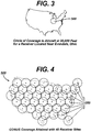
- One example employs a receiving network 500 comprising several spaced apart remote stations 200 as illustrated in FIG.4 .
- Remote stations 200 are spaced from each other so as to provide receiver coverage over the entire geographical area of interest 120, in this case the United States, as illustrated in FIG. 4 .
- the radio horizon for a line of sight path from an object at H feet above the earth is 2 ⁇ H miles.
- a radio receiver on the ground near Evendale, Ohio is capable of line of sight contact with a plane at 20,000 feet whose ground point falls in the circle 300 as shown in Figure 3 .
- the circle is about 200 miles in radius.
- Figure 4 shows a virtual covering of the Continental United States with only 40 receiver sites. A site center is marked with an "x".
- the system includes a protocol for fixing and monitoring schedule and performing monitoring hand-off from receiver site to receiver site.
- the protocol relies upon a ground-to-air link for flow or transmission control including.
- Examples of ground to air links suitable for transmission control include, but are not limited to: adaptive transmission rate control; provision/non-provision of error correction coding; power control; and time of transmission.
Claims (4)
- Système de télémesure (10) comprenant :une pluralité de télémètres (100), chaque télémètre (100) étant transporté à bord d'un aéronef respectif (20), lesdits télémètres comportant une entrée (320) couplée à la sortie d'un ou plusieurs détecteurs d'état desdites ressources respectives ; une sortie (150) pour fournir des messages de diagnostic contenant des informations relatives aux performances détectées desdites ressources respectives ;chaque ressource respective comprenant un transmetteur respectif (110) ayant une entrée couplée à ladite sortie desdits télémètres pour transmettre lesdits messages de diagnostic dans une bande de fréquences ISM ; etune pluralité de stations distantes (200) comprenant un récepteur (116) pour recevoir lesdits messages transmis ;un processeur (150) pour traiter lesdits messages transmis ; etune sortie (320) pour fournir des informations relatives à la performance desdites ressources respectives à un dispositif adapté à utiliser lesdites informations ;lesdites stations distantes (200) sont espacées les unes des autres de manière à fournir une couverture de récepteur sur toute une zone géographique d'intérêt ; et caractérisé en ce que :
ledit aéronef (20) comprend des nœuds en communication radio les uns avec les autres, et chaque nœud ayant un émetteur-récepteur (110, 116) respectif muni d'informations de plan de vol pour lui permettre de sélectionner un nœud successeur de telle sorte que lesdits messages sont transmis d'un nœud à l'autre tandis que le nœud successeur est en vue d'un nœud prédécesseur. - Système de télémesure (10) selon la revendication 1, dans lequel lesdits émetteurs (110) transmettent de l'énergie électromagnétique dans la bande industrielle / scientifique / médicale (ISM) de 2 400 - 2 483,5 MHz.
- Système de télémesure (10) selon la revendication 1 ou la revendication 2, dans lequel lesdits télémètres (100) comprennent en outre un récepteur respectif pour recevoir des messages de diagnostic dans la bande de fréquences ISM.
- Système de télémesure (10) selon la revendication 1 ou la revendication 3, dans lequel lesdits transmetteurs (10) transmettent dans la bande industrielle / scientifique / médicale (ISM) de 5 725 - 5 850 MHz.
Applications Claiming Priority (2)
| Application Number | Priority Date | Filing Date | Title |
|---|---|---|---|
| US09/561,576 US6781513B1 (en) | 1998-03-03 | 2000-04-28 | Telemetry of diagnostic messages from a mobile asset to a remote station |
| US561576 | 2000-04-28 |
Publications (2)
| Publication Number | Publication Date |
|---|---|
| EP1154388A1 EP1154388A1 (fr) | 2001-11-14 |
| EP1154388B1 true EP1154388B1 (fr) | 2020-02-19 |
Family
ID=24242543
Family Applications (1)
| Application Number | Title | Priority Date | Filing Date |
|---|---|---|---|
| EP01303630.6A Expired - Lifetime EP1154388B1 (fr) | 2000-04-28 | 2001-04-20 | Télémetrie de messages de diagnostic provenant d'une entité mobile et à destination d'une station à distance |
Country Status (3)
| Country | Link |
|---|---|
| EP (1) | EP1154388B1 (fr) |
| JP (1) | JP4954384B2 (fr) |
| CA (1) | CA2344000C (fr) |
Families Citing this family (7)
| Publication number | Priority date | Publication date | Assignee | Title |
|---|---|---|---|---|
| DE10261791A1 (de) * | 2002-12-23 | 2004-07-15 | Robert Bosch Gmbh | Vorrichtung zum Berührungsschutz und Verfahren zum Schutz von dem Berühren eines beweglichen Teils |
| US20100023201A1 (en) * | 2008-07-24 | 2010-01-28 | David Scott Kinney | Method and apparatus for obtaining vehicle data |
| US8301332B2 (en) | 2010-09-28 | 2012-10-30 | Ge Aviation Systems Llc | Method and system for fleet operations data management |
| DE102011054496B4 (de) * | 2011-10-14 | 2018-06-28 | Deutsches Zentrum für Luft- und Raumfahrt e.V. | Datenerfassungssystem und Verfahren hierzu |
| US20160197669A1 (en) | 2014-12-11 | 2016-07-07 | Tesla Wireless Company LLC | Communication method and system that uses low latency/low data bandwidth and high latency/high data bandwidth pathways |
| US10263690B2 (en) * | 2017-08-01 | 2019-04-16 | Viasat, Inc. | Handover based on predicted network conditions |
| CN110741419A (zh) | 2017-10-02 | 2020-01-31 | 松下知识产权经营株式会社 | 传感器装置及气体监视系统 |
Citations (3)
| Publication number | Priority date | Publication date | Assignee | Title |
|---|---|---|---|---|
| EP0748082A1 (fr) * | 1995-06-07 | 1996-12-11 | General Electric Company | Protocole et mécanisme pour la communication en mode "Mutter" pour une unité de localisation à maître stationnaire |
| US5742336A (en) * | 1996-12-16 | 1998-04-21 | Lee; Frederick A. | Aircraft surveillance and recording system |
| US5867801A (en) * | 1996-01-11 | 1999-02-02 | General Railway Signal Corporation | Remote asset monitoring system |
Family Cites Families (8)
| Publication number | Priority date | Publication date | Assignee | Title |
|---|---|---|---|---|
| JPS5445161A (en) * | 1977-09-10 | 1979-04-10 | Hitachi Denshi Ltd | Telemeter system |
| JPS5880796A (ja) * | 1981-11-05 | 1983-05-14 | 三菱電機株式会社 | テレメ−タのポ−リング方式 |
| US4804937A (en) | 1987-05-26 | 1989-02-14 | Motorola, Inc. | Vehicle monitoring arrangement and system |
| US5065321A (en) | 1989-06-15 | 1991-11-12 | Pulse Electronics, Inc. | Solid state event recorder |
| JPH0385699A (ja) * | 1989-08-30 | 1991-04-10 | Kawasaki Steel Corp | 機械設備の異常検知方法 |
| FR2693068B1 (fr) | 1992-06-25 | 1995-05-24 | France Etat Armement | Système de télémesure des paramètres d'un engin mobile. |
| JP3215521B2 (ja) * | 1992-09-18 | 2001-10-09 | 愛知時計電機株式会社 | データ収集装置 |
| JP3180888B2 (ja) * | 1995-04-30 | 2001-06-25 | 東京瓦斯株式会社 | 遠隔監視装置 |
-
2001
- 2001-04-12 CA CA002344000A patent/CA2344000C/fr not_active Expired - Fee Related
- 2001-04-20 EP EP01303630.6A patent/EP1154388B1/fr not_active Expired - Lifetime
- 2001-04-27 JP JP2001130612A patent/JP4954384B2/ja not_active Expired - Lifetime
Patent Citations (3)
| Publication number | Priority date | Publication date | Assignee | Title |
|---|---|---|---|---|
| EP0748082A1 (fr) * | 1995-06-07 | 1996-12-11 | General Electric Company | Protocole et mécanisme pour la communication en mode "Mutter" pour une unité de localisation à maître stationnaire |
| US5867801A (en) * | 1996-01-11 | 1999-02-02 | General Railway Signal Corporation | Remote asset monitoring system |
| US5742336A (en) * | 1996-12-16 | 1998-04-21 | Lee; Frederick A. | Aircraft surveillance and recording system |
Also Published As
| Publication number | Publication date |
|---|---|
| CA2344000C (fr) | 2009-07-14 |
| CA2344000A1 (fr) | 2001-10-28 |
| JP2002056487A (ja) | 2002-02-22 |
| JP4954384B2 (ja) | 2012-06-13 |
| EP1154388A1 (fr) | 2001-11-14 |
Similar Documents
| Publication | Publication Date | Title |
|---|---|---|
| US6781513B1 (en) | Telemetry of diagnostic messages from a mobile asset to a remote station | |
| EP1060462B1 (fr) | Telemetrie de messages diagnostiques emanant d'une entite mobile a destination d'une station a distance | |
| US6775545B2 (en) | Wireless, ground link-based aircraft data communication system with roaming feature | |
| EP2727260B1 (fr) | Réutilisation de spectre par un systeme de communication entre aeronef et des stations au sol et un système existant de satellite géostationnaire | |
| EP1154388B1 (fr) | Télémetrie de messages de diagnostic provenant d'une entité mobile et à destination d'une station à distance | |
| CN110445530B (zh) | 一种机载物联网终端及信息传输方法 | |
| Ahmad et al. | Wi-fly: Widespread opportunistic connectivity via commercial air transport | |
| Kerczewski et al. | UAS CNPC satellite link performance—Sharing spectrum with terrestrial systems | |
| RU2223549C1 (ru) | Телеизмерение диагностических сообщений от подвижных объектов к удаленной станции | |
| MXPA00008605A (es) | Telemetria de mensajes de diagnostico de un objeto movil a una estacion remota | |
| US20230021977A1 (en) | Wireless system, receiving relay station device and transmitting control method | |
| CN117955546A (zh) | 基于空频域隔离的低轨星座对地数传频率划分方法及系统 | |
| WO2004057777A2 (fr) | Plate-forme mobile destinee a regulariser la qualite d'une communication par satellite | |
| Mohd et al. | Electromagnetic compatibility between spread spectrum and conventional telemetry systems: The key to a new era for DOD test ranges | |
| BOOK | Wireless network communications overview for space mission operations | |
| Lunsford | Datalink Requirements for the Enhanced Range Applications Program (EnRAP) Meeting the Future Wireless Data Transfer Needs of the Test Community | |
| Turner | AN OVER THE HORIZON COMMAND/DATA LINK SYSTEM | |
| Cahn et al. | Integrated Function (CNI) Waveform Study |
Legal Events
| Date | Code | Title | Description |
|---|---|---|---|
| PUAI | Public reference made under article 153(3) epc to a published international application that has entered the european phase |
Free format text: ORIGINAL CODE: 0009012 |
|
| AK | Designated contracting states |
Kind code of ref document: A1 Designated state(s): DE FR GB Kind code of ref document: A1 Designated state(s): AT BE CH CY DE DK ES FI FR GB GR IE IT LI LU MC NL PT SE TR |
|
| AX | Request for extension of the european patent |
Free format text: AL;LT;LV;MK;RO;SI |
|
| RIN1 | Information on inventor provided before grant (corrected) |
Inventor name: MCKINNEY, WILLIAM ROBERT SR. Inventor name: SCHINGS, BRUCE GUNTER Inventor name: ROSS, JAOHN ANDERSON FERGUS Inventor name: KORKOSZ, RICHARD A. Inventor name: AL-DHAHIR, NAOFEL MOHAMMED WASSEL Inventor name: HERSHEY, JOHN ERIK Inventor name: PUCKETTE, CHARLES MCDONALD Inventor name: TOMLINSON, HAROLD WOODRUFF JR. |
|
| 17P | Request for examination filed |
Effective date: 20020514 |
|
| AKX | Designation fees paid |
Free format text: DE FR GB |
|
| 17Q | First examination report despatched |
Effective date: 20031218 |
|
| GRAP | Despatch of communication of intention to grant a patent |
Free format text: ORIGINAL CODE: EPIDOSNIGR1 |
|
| INTG | Intention to grant announced |
Effective date: 20190919 |
|
| RIN1 | Information on inventor provided before grant (corrected) |
Inventor name: PUCKETTE, CHARLES MCDONALD Inventor name: TOMLINSON, HAROLD WOODRUFF JR. Inventor name: ROSS, JAOHN ANDERSON FERGUS Inventor name: AL-DHAHIR, NAOFEL MOHAMMED WASSEL Inventor name: SCHINGS, BRUCE GUNTER Inventor name: KORKOSZ, RICHARD A. Inventor name: MCKINNEY, WILLIAM ROBERT SR. Inventor name: HERSHEY, JOHN ERIK |
|
| GRAS | Grant fee paid |
Free format text: ORIGINAL CODE: EPIDOSNIGR3 |
|
| GRAA | (expected) grant |
Free format text: ORIGINAL CODE: 0009210 |
|
| AK | Designated contracting states |
Kind code of ref document: B1 Designated state(s): DE FR GB |
|
| REG | Reference to a national code |
Ref country code: GB Ref legal event code: FG4D |
|
| REG | Reference to a national code |
Ref country code: DE Ref legal event code: R096 Ref document number: 60151240 Country of ref document: DE |
|
| PGFP | Annual fee paid to national office [announced via postgrant information from national office to epo] |
Ref country code: FR Payment date: 20200518 Year of fee payment: 20 Ref country code: DE Payment date: 20200514 Year of fee payment: 20 |
|
| PGFP | Annual fee paid to national office [announced via postgrant information from national office to epo] |
Ref country code: GB Payment date: 20200512 Year of fee payment: 20 |
|
| REG | Reference to a national code |
Ref country code: DE Ref legal event code: R097 Ref document number: 60151240 Country of ref document: DE |
|
| PLBE | No opposition filed within time limit |
Free format text: ORIGINAL CODE: 0009261 |
|
| STAA | Information on the status of an ep patent application or granted ep patent |
Free format text: STATUS: NO OPPOSITION FILED WITHIN TIME LIMIT |
|
| 26N | No opposition filed |
Effective date: 20201120 |
|
| REG | Reference to a national code |
Ref country code: DE Ref legal event code: R071 Ref document number: 60151240 Country of ref document: DE |
|
| REG | Reference to a national code |
Ref country code: GB Ref legal event code: PE20 Expiry date: 20210419 |
|
| PG25 | Lapsed in a contracting state [announced via postgrant information from national office to epo] |
Ref country code: GB Free format text: LAPSE BECAUSE OF EXPIRATION OF PROTECTION Effective date: 20210419 |