BACKGROUND OF THE INVENTION
Field of the Invention
The present invention relates to an optical fiber
apparatus having a fusion-spliced portion in which two
optical fibers are fusion-spliced, and a fabrication
method thereof.
Related Background Art
As methods of cascade connection between two
optical fibers, there are connector splice and fusion
splice. Among these, the fusion splice is a method of
aligning two optical fibers each other and heating end
faces of the respective fibers to cause fusion thereof,
and has the advantage of low splice loss. On the other
hand, however, the fusion splice had the problem that
the mechanical strength of the fusion-spliced portion
was lower than that of the other portions of the
optical fibers. Conventionally, in order to reinforce
the fusion-spliced portion in the optical fiber
apparatus including it, a steel wire was placed along
the fusion-spliced portion and the whole of these were
coated with resin.
SUMMARY OF THE INVENTION
The reinforcing method of the spliced portion
with the steel wire as described above, however, has
the following problems. Namely, the outside diameter
of the reinforced portion (the portion along with the
steel wire) including the spliced portion becomes
larger than that of the other portions of the optical
fibers. With increase in the outside diameter of the
reinforced portion along with the steel wire, stress
will be exerted on the optical fibers around this
reinforced portion during the procedure of forming a
cable from the two optical fibers spliced in cascade
connection including this reinforced portion, during
the procedure of forming a module by winding the fibers
around a bobbin, or during other mounting procedures,
so that it will raise the risk of fracture of the
optical fibers or increase loss of light propagating in
the optical fibers. It also becomes harder to bend
this reinforced portion during the procedure of winding
the two optical fibers including the reinforced portion
around the bobbin. For the optical fiber apparatus
having the fusion-spliced portion, as described, it is
sometimes undesirable to employ the reinforcement of
the fusion-spliced portion with the steel wire,
depending upon mounting forms or uses.
The present invention has been accomplished to
solve the above problems and an object of the present
invention is thus to provide an optical fiber apparatus
that secures the satisfactory mechanical strength of
the fusion-spliced portion without use of the
reinforcement with the steel wire, and a method of
fabricating the optical fiber apparatus.
A fabrication method of optical fiber apparatus
according to the present invention is a method of
fabricating optical fiber apparatus having a fusion-spliced
portion in which respective end faces of two
optical fibers are spliced each other by fusion splice,
which comprises a fusion step of heating the end faces
of the two optical fibers to cause fusion thereof,
thereby forming the fusion-spliced portion, and a
thermal-strain-removing step of removing thermal strain
by a heating treatment of a wider region than the
heated area of the fusion-spliced portion, at a
temperature of not less than 500°C nor more than 1500°C.
There occurs thermal strain in and around the
fusion-spliced portion during the fusion step, but this
thermal strain is removed by the heating treatment of
the wider region than the heated area of the fusion-spliced
portion, at the temperature of not less than
500°C nor more than 1500°C according to the present
invention, which ensures the satisfactory mechanical
strength in and around the fusion-spliced portion of
the optical fiber apparatus. Here the "heated region"
stated in the present invention means a region in which
the temperature becomes 500°C and higher during the
heating of the optical fibers. The fusion-spliced
portion is cooled after the removal of the thermal
strain, and the removed state of thermal strain is also
maintained during this cooling, thus ensuring the
adequate mechanical strength in and around the fusion-spliced
portion of the optical fiber apparatus. A rate
of the cooling is preferably not more than 4000°C/min.
The fabrication method of optical fiber apparatus
according to the present invention is characterized in
that in the thermal-strain-removing step the
aforementioned heating treatment is carried out by use
of arc discharge, flame generated with supply of
inflammable gas and oxygen gas to a burner, or a heater.
In either of these cases, the optical fibers are heated
at the appropriate temperature in and around the
fusion-spliced portion thereof during the thermal-strain-removing
step, so as to remove the thermal
strain caused during the fusion step. The heating by
arc discharge is a preferred method, because a fusion
splicing machine can be used as it is. The heating by
the burner is another preferred method, because it
permits distribution heating in and around the fusion-spliced
portion of the optical fiber apparatus and also
permits use of a compact heating unit. The heating by
the heater is another preferred method, because it
permits distribution heating in and around the fusion-spliced
portion of the optical fiber apparatus and
keeps a heating atmosphere clean.
An optical fiber apparatus according to the
present invention is characterized by being fabricated
by the aforementioned fabrication method of optical
fiber apparatus according to the present invention.
Since the thermal strain caused in the fusion step is
removed from this optical fiber apparatus during the
thermal-strain-removing step, the satisfactory
mechanical strength is ensured in and around the
fusion-spliced portion, without use of the
reinforcement with the steel wire.
The optical fiber apparatus stated herein means
one having the fusion-spliced portion in which two or
more optical fibers are spliced each other by fusion
splice, and involves optical fiber transmission lines
to be laid, modules or bobbins, and other forms.
The present invention will be more fully
understood from the detailed description given
hereinbelow and the accompanying drawings, which are
given by way of illustration only and are not to be
considered as limiting the present invention.
Further scope of applicability of the present
invention will become apparent from the detailed
description given hereinafter. However, it should be
understood that the detailed description and specific
examples, while indicating preferred embodiments of the
invention, are given by way of illustration only, since
the invention can be practised within the scope of the
appended claims with various changes and modifications.
BRIEF DESCRIPTION OF THE DRAWINGS
Fig. 1A to Fig. 1F are step diagrams to illustrate
a fabrication method of optical fiber apparatus
according to the present invention;
Fig. 2 is a schematic block diagram of a system
for carrying out the thermal-strain-removing step in
the fabrication method of optical fiber apparatus
according to the present invention;
Fig. 3 is a perspective view to show a heating
system provided with a burner;
Fig. 4 is a perspective view to show a heating
system provided with a heater;
Fig. 5 is a perspective view to show a heating
system provided with a discharge section for arc
discharge; and
Fig. 6 is a graph to show a relation between
heating temperature in the thermal-strain-removing step
and 50% rupture strength.
DESCRIPTION OF THE PREFERRED EMBODIMENTS
The preferred embodiments of the present
invention will be described hereinafter in detail with
reference to the accompanying drawings. It is noted
that in the description of the drawings the same
elements will be denoted by the same reference symbols
and redundant description will be omitted.
First described is how the inventors accomplished
the present invention. The inventors researched the
reason why the mechanical strength of the fusion-spliced
portion was lower than that of the other
portions of the optical fibers in the optical fiber
apparatus having the fusion-spliced portion, and found
that the cause was the thermal strain due to the local
heating at high temperature only at and in the close
vicinity of the end faces of the two optical fibers
during the fusion step. Describing in more detail,
there occurs the thermal strain in the fusion-spliced
portion during the fusion procedure of heating the
glass end faces of the respective optical fibers to the
temperature at which glass is adequately softened, and
the thermal strain remains during cooling of the
optical fibers thereafter. We can observe the thermal
strain remaining in this fusion-spliced portion with an
interference microscope or the like. The thermal
strain is greatest at the both ends of the heated
region of the fusion-spliced portion. If the thermal
strain is left in the fusion-spliced portion, the
fusion-spliced portion can break during a post-step, so
as to lower the fabrication yield of optical fiber
apparatus. In this case the optical fiber apparatus is
most fragile at the both ends of the heated region
during the fusion splice. The present invention has
been accomplished based on the above knowledge and
involves the removal of thermal strain by the heating
treatment of heating the region in and around the
fusion-spliced portion at the appropriate temperature
after the fusion step, thereby ensuring the sufficient
mechanical strength of the fusion-spliced portion of
optical fiber apparatus.
In the next place, the steps in the fabrication
method of optical fiber apparatus according to the
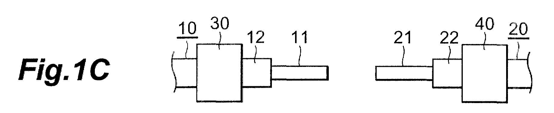
present embodiment will be described. Fig. 1A to Fig.
1F are the step diagrams to illustrate the fabrication
method of optical fiber apparatus according to the
present embodiment. In the first step, two optical
fibers 10 and 20 to be spliced each other are prepared
(Fig. 1A). The optical fibers 10, 20 are those formed
by coating the periphery of silica-glass-based glass
fibers 11, 21 with resin 12, 22. Then the coatings of
resin 12, 22 are removed from the end portions of the
respective optical fibers 10, 20, thereby exposing the
glass fibers 11, 21 in the end portions (Fig. 1B). The
removal of the coatings of resin 12, 22 is chemically
carried out, for example, with hot concentrated
sulfuric acid and thereafter, the sulfuric acid is
washed away with water or acetone. Then end portions
of the glass fibers 11, 21 are cut by a fiber cutter,
these optical fibers 10, 20 after the removal of the
coatings from their end portions are held by fiber
holders 30, 40 of a fusion splicer, and the glass
fibers 11, 21 are aligned each other (Fig. 1C).
After the alignment, the fusion step is carried
out to heat the end faces of the glass fibers 11, 21 to
cause fusion thereof to form the fusion-spliced portion
A (Fig. 1D). Specifically, the end faces of the glass
fibers 11, 21 are preheated and shaped, the end faces
of the glass fibers 11, 21 are pressed against each
other to be spliced, and the glass fibers are shaped
and heated around the fusion-spliced portion A. A
heating unit used herein will be described later. A
region R1 surrounded by a dashed line in the figure
represents the heated region in this fusion step. The
heated region is a region in which the temperature
becomes 500°C and higher. In the fusion procedure, the
temperature at the both ends of the heated region R1 is
lower than the temperature of the fiber spliced portion
in the center, so that the thermal strain is large near
the both ends of the heated region in the glass fibers
11, 21, so as to make the fibers easy to break there.
After the fusion step, the thermal-strain-removing
step is carried out to remove the thermal
strain by the heat treatment of a wider region R2 than
the above heated region R1 in and around the fusion-spliced
portion A, at the temperature of not less than
500°C nor more than 1500°C (Fig. 1E). In other words,
the region of the temperature of 500°C and higher in
this thermal-strain-removing step, is wider than that
during the heating in the above fusion step. The
heating temperature range of 500°C to 1500°C in this
thermal-strain-removing step is not more than the
softening temperature of the glass fibers 11, 21 and is
sufficient to remove the thermal strain. A sufficient
heating period during the thermal-strain-removing step
can be as short as about several seconds to about
several ten seconds. The heating treatment in this
thermal-strain-removing step removes the thermal strain
caused around the fusion-spliced portion A during the
fusion step and recovers the mechanical strength around
the fusion-spliced portion A. Then the region in and
around the fusion-spliced portion A is cooled after the
thermal-strain-removing step. A cooling rate in this
cooling step is preferably not more than 4000°C/min.
After the cooling, the glass fibers 11, 21
exposed are again coated with resin 52 (Fig. 1F). The
outside diameter of this coating of resin 52 is
approximately equal to that of the coatings of resin 12,
22 of the optical fibers 10, 20. After that,
predetermined mounting procedures, e.g. a procedure of
winding the optical fibers 10, 20 including the fusion-spliced
portion A around a bobbin, are carried out,
thereby fabricating an optical fiber apparatus 1. The
optical fiber apparatus 1 fabricated in this way has
sufficient mechanical strength in and around the
fusion-spliced portion A without use of the
reinforcement with the steel wire, because the thermal
strain caused during the fusion step is removed in the
thermal-strain-removing step.
Fig. 2 is a block diagram of a system for
carrying out the thermal-strain-removing step in the
fabrication method of optical fiber apparatus according
to the present embodiment. As illustrated in this
figure, the system is provided with a heat source 60
for heating the region in and around the fusion-spliced
portion A and a radiation thermometer 70 for measuring
the temperature in and around the fusion-spliced
portion A, which are placed near the fusion-spliced
portion A. The temperature in and around the fusion-spliced
portion A is measured by the radiation
thermometer 70, and the heating in and around the
fusion-spliced portion A by the heat source 60 is
controlled so that the temperature measured by the
infrared radiation thermometer 70 becomes an adequate
value.
The heat source 60 is electrodes for arc
discharge, a burner, or a heater (an electric heater, a
ceramic heater, or the like).
Fig. 3 shows a heating system using a burner.
This heating system is provided with a burner 62, a
driving device 72 for reciprocally moving the burner 62
along the axial direction of the fibers, a gas supply
unit 82 for supplying gas to the burner 62, and a
control unit 92 for controlling a gas supply amount of
the gas supply unit 82 and a driving distance of the
driving unit 72, based on the temperature information
from the radiation thermometer 70. The optical fibers
10, 20 with the glass fibers 11, 21 being spliced are
held by fiber holders 30, 40.
The radiation thermometer 70 is a combination of
a two-dimensional infrared radiation thermometer with a
magnifying lens, and measures a temperature
distribution in and around the fusion-spliced portion A
through the magnifying lens by the two-dimensional
infrared radiation thermometer. The emissivity is set
to 0.5 in consideration of the shape and material of
the glass fibers 11, 21 as a measured object. In the
thermal-strain-removing step, the heat source 60 is
placed or moved along the axial direction of the fibers
so that the temperature distribution measured by this
radiation thermometer 70 satisfies the aforementioned
relation between the heated region R1 and the heated
region R2.
Upon activation of this system in this structure,
flame is generated with supply of inflammable gas
(hydrocarbon gas, e.g., propane gas) and oxygen gas
from the gas supply unit 82 to the burner 62, so as to
be able to carry out the heating treatment to heat the
region in and around the fusion-spliced portion A by
this flame. The use of the burner 62 as the heat
source 60 is preferred, because it permits the
distribution heating in and around the fusion-spliced
portion A and the use of the compact heating unit.
Fig. 4 shows a heating system using a heater.
This heating system is provided with a heater 64, a
driving unit 74 for reciprocally moving the heater 64
along the axial direction of the fibers, a power supply
unit 84 for supplying power to the heater 64, and a
control unit 94 for controlling a power supply amount
of the power supply unit 84 and a driving distance of
the driving unit 74, based on the temperature
information from the radiation thermometer 70.
Upon activation of the system in this structure,
the power supply unit 84 supplies the power to the
heater 64 to heat the heater up, thereby implementing
the heating treatment of the region in and around the
fusion-spliced portion A. The use of the heater 64 as
the heat source 60 is preferred, because it permits the
distribution heating in and around the fusion-spliced
portion A and keeps the heating atmosphere clean.
Fig. 5 shows a heating system of an arc discharge
type. This heating system is provided with a discharge
section 66 consisting of a pair of electrodes opposed
to each other, a driving unit 76 for reciprocally
moving the discharge section 66 along the axial
direction of the fibers, a power supply unit 86 for
supplying power to the discharge section 66, and a
control unit 96 for controlling a power supply amount
of the power supply unit 86 and a driving distance of
the driving unit 76, based on the temperature
information from the radiation thermometer.
Upon activation of the system in this structure,
the power supply unit 86 supplies the power to the
discharge section 66 to induce arc discharge, thereby
implementing the heating treatment in and around the
fusion-spliced portion A. The use of the discharge
section 66 as the heat source 60 is preferred, because
the fusion splicer can be used as it is.
In the next place, specific examples of the
fabrication method of optical fiber apparatus according
to the present embodiment will be described. In
Examples 1 to 4 below, single-mode optical fibers of
one kind with the core region of silica glass base
doped with GeO2, were used as the optical fibers 10, 20.
In Example 5, optical fibers of two kinds having
mutually different mode field diameters were used as
the optical fibers 10, 20.
In Example 1, the arc discharge was used in the
thermal-strain-removing step. Specifically, the end
faces of the glass fibers 11, 21 were spliced by arc
discharge, using the fusion splicer, and in the
thermal-strain-removing step thereafter, the fusion
splicer was also used as it was. The thermal strain
was removed by heating the wider range than the heated
region during the fusion splice, at the heating
temperature of 1500°C in and around the fusion-spliced
portion while moving the arc discharge electrodes in
the longitudinal direction of the fibers around the
fusion-spliced portion. The heating period in this
thermal-strain-removing step was 10 seconds. Twenty
optical fiber apparatus having the fusion-spliced
portion were fabricated in this way. A tensile rupture
test was carried out for each of the twenty optical
fiber apparatus. The 50% rupture strength, which is a
strength at which 50% optical fiber apparatus, i.e.,
ten optical fiber apparatus break, was 24.5 N (2.5 kg)
and the rupture strength of sixteen optical fiber
apparatus was not less than 19.6 N (2.0 kg), thus
meeting with good results.
In Example 2, a compact burner was used in the
thermal-strain-removing step. Specifically, the end
faces of the glass fibers 11, 21 were spliced each
other by arc discharge, using the fusion splicer, and
in the thermal-strain-removing step thereafter, another
heating unit was used to remove the thermal strain by
heating the wider range than the heated region during
the fusion splice, in and around the fusion-spliced
portion while moving the compact burner along the
longitudinal direction around the fusion-spliced
portion. In this thermal-strain-removing step the
heating temperature was 500°C and the heating period
was 20 seconds. At this time, propane gas and oxygen
gas was supplied to the burner. Twenty optical fiber
apparatus having the fusion-spliced portion were
fabricated in this way. The tensile rupture test was
conducted for each of the twenty optical fiber
apparatus. The 50% rupture strength was 24.5 N (2.5
kg) and the rupture strength of eighteen optical fiber
apparatus was not less than 19.6 N (2.0 kg), thus
meeting with good results.
In Example 3, an electric heater was used in the
thermal-strain-removing step. Specifically, the end
faces of the glass fibers 11, 21 were spliced each
other by arc discharge, using the fusion splicer, and
in the thermal-strain-removing step thereafter, another
heating device was used to remove the thermal strain by
heating the wider range than the heated region during
the fusion splice, in and around the fusion-spliced
portion while moving the electric heater along the
longitudinal direction around the fusion-spliced
portion. In this thermal-strain-removing step the
heating temperature was 1000°C and the heating period
10 seconds. Twenty optical fiber apparatus having the
fusion-spliced portion were fabricated in this way.
The tensile rupture test was carried out for each of
the twenty optical fiber apparatus. The 50% rupture
strength was 25.48 N (2.6 kg) and the rupture strength
of seventeen optical fiber apparatus was not less than
19.6 N (2.0 kg), thus meeting with good results.
In Example 4, the arc discharge was used in the
thermal-strain-removing step. Specifically, the end
faces of the glass fibers 11, 21 were spliced each
other by arc discharge, using the fusion splicer, and
in the thermal-strain-removing step thereafter, the
fusion splicer was also used as it was, to remove the
thermal strain by heating the wider range than the
heated region during the fusion splice, at each of
heating temperatures in the range of near room
temperature to 1800°C in and around the fusion-spliced
portion while moving the arc discharge electrodes along
the longitudinal direction around the fusion-spliced
portion. In the thermal-strain-removing step the
heating period was 10 seconds. Twenty optical fiber
apparatus having the fusion-spliced portion were
fabricated under each of the temperature conditions and
the tensile rupture test was conducted for each of the
twenty optical fiber elements.
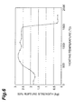
Fig. 6 is a graph to show the relation between
50% rupture strength and heating temperature in the
thermal-strain-removing step. As apparent from this
graph, the 50% rupture strength was not less than 24.5
N (2.5 kg) in the heating temperature range of not less
than 500°C nor more than 1500°C in the thermal-strain-removing
step and thus the satisfactory mechanical
strength was able to be ensured for the fusion-spliced
portion of the optical fiber apparatus. In the heating
temperature range of less than 500°C, no improvement
was seen in the mechanical strength of the fusion-spliced
portion of the optical fiber apparatus. In the
heating temperature range over 1500°C, the glass
surface was crystallized in part near the fusion-spliced
portion of the optical fiber apparatus, so as
to further lower the strength of the fusion-spliced
portion of the optical fiber apparatus. Similar
results were obtained where the heat source was either
of the arc discharge, the burner, and the heater.
According to the fabrication method of optical
fiber apparatus in the present embodiment, as described
above, the end faces of the glass fibers 11, 21 were
heated to cause fusion thereof to form the fusion-spliced
portion in the fusion step, and in the thermal-strain-removing
step thereafter, the heating treatment
was carried out to heat the region in and around the
fusion-spliced portion (the wider range than the heated
region during the fusion splice) at the temperature of
not less than 500°C nor more than 1500°C, thereby
removing the thermal strain. The thermal strain is
caused in and around the fusion-spliced portion during
the fusion step, but this thermal strain is removed
during the thermal-strain-removing step at the
temperature of not less than 500°C nor more than 1500°C.
Therefore, the sufficient mechanical strength is
ensured in and around the fusion-spliced portion of the
optical fiber apparatus. According to the examples,
the 50% rupture strength of the optical fiber apparatus
was not less than 24.5 N (2.5 kg) thanks to this
thermal-strain-removing step.
As detailed above, the fabrication method of
optical fiber apparatus according to the present
invention is the method having the fusion step of
heating the end faces of two optical fibers to cause
fusion thereof to form the fusion-spliced portion, and
the thermal-strain-removing step thereafter of removing
the thermal strain by the heating treatment of the
region in and around the fusion-spliced portion (the
wider range than the heated region during the fusion
splice) at the temperature of not less than 500°C nor
more than 1500°C, followed by cooling. The thermal
strain occurs in and around the fusion-spliced portion
during the fusion step, but this thermal strain is
removed in the thermal-strain-removing step at the
temperature of not less than 500°C nor more than 1500°C.
Therefore, the sufficient mechanical strength is
ensured in and around the fusion-spliced portion of
optical fiber apparatus. The removed state of thermal
strain is also maintained during the cooling after the
thermal-strain-removing step, so that the satisfactory
mechanical strength is ensured in and around the
fusion-spliced portion of optical fiber apparatus.
As described above, the satisfactory mechanical
strength of the fusion-spliced portion is ensured
without use of the reinforcement with the steel wire,
in the optical fiber apparatus fabricated by the
fabrication method of optical fiber apparatus according
to the present invention. Therefore, the outside
diameter of the fusion-spliced portion is not larger
than that of the other portions of the optical fibers
and thus the stress exerted on the optical fibers
around the fusion-spliced portion is relieved during
the procedure of forming a cable from the two optical
fibers including the fusion-spliced portion, during a
procedure of forming a module by winding the fibers
around a bobbin, or during other mounting procedures.
Further, the risk of fracture of optical fibers is
reduced and increase is suppressed in loss of the light
propagating in the optical fibers. In addition, the
fusion-spliced portion can be readily bent when the two
optical fibers including the fusion-spliced portion are
wound around the bobbin.