EP1154252A1 - Temperature measuring system and optical switch used therein - Google Patents
Temperature measuring system and optical switch used therein Download PDFInfo
- Publication number
- EP1154252A1 EP1154252A1 EP01304102A EP01304102A EP1154252A1 EP 1154252 A1 EP1154252 A1 EP 1154252A1 EP 01304102 A EP01304102 A EP 01304102A EP 01304102 A EP01304102 A EP 01304102A EP 1154252 A1 EP1154252 A1 EP 1154252A1
- Authority
- EP
- European Patent Office
- Prior art keywords
- rotor
- fiber optic
- optic cable
- rotational axis
- optical
- Prior art date
- Legal status (The legal status is an assumption and is not a legal conclusion. Google has not performed a legal analysis and makes no representation as to the accuracy of the status listed.)
- Granted
Links
Images


Classifications
-
- G—PHYSICS
- G02—OPTICS
- G02B—OPTICAL ELEMENTS, SYSTEMS OR APPARATUS
- G02B6/00—Light guides; Structural details of arrangements comprising light guides and other optical elements, e.g. couplings
- G02B6/24—Coupling light guides
- G02B6/26—Optical coupling means
- G02B6/35—Optical coupling means having switching means
- G02B6/3502—Optical coupling means having switching means involving direct waveguide displacement, e.g. cantilever type waveguide displacement involving waveguide bending, or displacing an interposed waveguide between stationary waveguides
- G02B6/3504—Rotating, tilting or pivoting the waveguides, or with the waveguides describing a curved path
-
- G—PHYSICS
- G01—MEASURING; TESTING
- G01K—MEASURING TEMPERATURE; MEASURING QUANTITY OF HEAT; THERMALLY-SENSITIVE ELEMENTS NOT OTHERWISE PROVIDED FOR
- G01K11/00—Measuring temperature based upon physical or chemical changes not covered by groups G01K3/00, G01K5/00, G01K7/00 or G01K9/00
- G01K11/32—Measuring temperature based upon physical or chemical changes not covered by groups G01K3/00, G01K5/00, G01K7/00 or G01K9/00 using changes in transmittance, scattering or luminescence in optical fibres
-
- G—PHYSICS
- G01—MEASURING; TESTING
- G01J—MEASUREMENT OF INTENSITY, VELOCITY, SPECTRAL CONTENT, POLARISATION, PHASE OR PULSE CHARACTERISTICS OF INFRARED, VISIBLE OR ULTRAVIOLET LIGHT; COLORIMETRY; RADIATION PYROMETRY
- G01J1/00—Photometry, e.g. photographic exposure meter
- G01J1/42—Photometry, e.g. photographic exposure meter using electric radiation detectors
-
- G—PHYSICS
- G01—MEASURING; TESTING
- G01J—MEASUREMENT OF INTENSITY, VELOCITY, SPECTRAL CONTENT, POLARISATION, PHASE OR PULSE CHARACTERISTICS OF INFRARED, VISIBLE OR ULTRAVIOLET LIGHT; COLORIMETRY; RADIATION PYROMETRY
- G01J3/00—Spectrometry; Spectrophotometry; Monochromators; Measuring colours
- G01J3/02—Details
- G01J3/0205—Optical elements not provided otherwise, e.g. optical manifolds, diffusers, windows
- G01J3/0218—Optical elements not provided otherwise, e.g. optical manifolds, diffusers, windows using optical fibers
-
- G—PHYSICS
- G01—MEASURING; TESTING
- G01J—MEASUREMENT OF INTENSITY, VELOCITY, SPECTRAL CONTENT, POLARISATION, PHASE OR PULSE CHARACTERISTICS OF INFRARED, VISIBLE OR ULTRAVIOLET LIGHT; COLORIMETRY; RADIATION PYROMETRY
- G01J5/00—Radiation pyrometry, e.g. infrared or optical thermometry
- G01J5/0022—Radiation pyrometry, e.g. infrared or optical thermometry for sensing the radiation of moving bodies
-
- G—PHYSICS
- G01—MEASURING; TESTING
- G01J—MEASUREMENT OF INTENSITY, VELOCITY, SPECTRAL CONTENT, POLARISATION, PHASE OR PULSE CHARACTERISTICS OF INFRARED, VISIBLE OR ULTRAVIOLET LIGHT; COLORIMETRY; RADIATION PYROMETRY
- G01J5/00—Radiation pyrometry, e.g. infrared or optical thermometry
- G01J5/0088—Radiation pyrometry, e.g. infrared or optical thermometry in turbines
-
- G—PHYSICS
- G01—MEASURING; TESTING
- G01J—MEASUREMENT OF INTENSITY, VELOCITY, SPECTRAL CONTENT, POLARISATION, PHASE OR PULSE CHARACTERISTICS OF INFRARED, VISIBLE OR ULTRAVIOLET LIGHT; COLORIMETRY; RADIATION PYROMETRY
- G01J5/00—Radiation pyrometry, e.g. infrared or optical thermometry
- G01J5/02—Constructional details
- G01J5/08—Optical arrangements
- G01J5/0818—Waveguides
- G01J5/0821—Optical fibres
-
- G—PHYSICS
- G01—MEASURING; TESTING
- G01J—MEASUREMENT OF INTENSITY, VELOCITY, SPECTRAL CONTENT, POLARISATION, PHASE OR PULSE CHARACTERISTICS OF INFRARED, VISIBLE OR ULTRAVIOLET LIGHT; COLORIMETRY; RADIATION PYROMETRY
- G01J5/00—Radiation pyrometry, e.g. infrared or optical thermometry
- G01J5/02—Constructional details
- G01J5/08—Optical arrangements
- G01J5/0831—Masks; Aperture plates; Spatial light modulators
-
- G—PHYSICS
- G01—MEASURING; TESTING
- G01J—MEASUREMENT OF INTENSITY, VELOCITY, SPECTRAL CONTENT, POLARISATION, PHASE OR PULSE CHARACTERISTICS OF INFRARED, VISIBLE OR ULTRAVIOLET LIGHT; COLORIMETRY; RADIATION PYROMETRY
- G01J5/00—Radiation pyrometry, e.g. infrared or optical thermometry
- G01J5/02—Constructional details
- G01J5/08—Optical arrangements
- G01J5/084—Adjustable or slidable
-
- G—PHYSICS
- G01—MEASURING; TESTING
- G01J—MEASUREMENT OF INTENSITY, VELOCITY, SPECTRAL CONTENT, POLARISATION, PHASE OR PULSE CHARACTERISTICS OF INFRARED, VISIBLE OR ULTRAVIOLET LIGHT; COLORIMETRY; RADIATION PYROMETRY
- G01J5/00—Radiation pyrometry, e.g. infrared or optical thermometry
- G01J5/02—Constructional details
- G01J5/08—Optical arrangements
- G01J5/0846—Optical arrangements having multiple detectors for performing different types of detection, e.g. using radiometry and reflectometry channels
-
- G—PHYSICS
- G01—MEASURING; TESTING
- G01J—MEASUREMENT OF INTENSITY, VELOCITY, SPECTRAL CONTENT, POLARISATION, PHASE OR PULSE CHARACTERISTICS OF INFRARED, VISIBLE OR ULTRAVIOLET LIGHT; COLORIMETRY; RADIATION PYROMETRY
- G01J5/00—Radiation pyrometry, e.g. infrared or optical thermometry
- G01J5/02—Constructional details
- G01J5/08—Optical arrangements
- G01J5/0879—Optical elements not provided otherwise, e.g. optical manifolds, holograms, cubic beamsplitters, non-dispersive prisms or particular coatings
-
- G—PHYSICS
- G01—MEASURING; TESTING
- G01J—MEASUREMENT OF INTENSITY, VELOCITY, SPECTRAL CONTENT, POLARISATION, PHASE OR PULSE CHARACTERISTICS OF INFRARED, VISIBLE OR ULTRAVIOLET LIGHT; COLORIMETRY; RADIATION PYROMETRY
- G01J5/00—Radiation pyrometry, e.g. infrared or optical thermometry
- G01J5/02—Constructional details
- G01J5/08—Optical arrangements
- G01J5/0893—Arrangements to attach devices to a pyrometer, i.e. attaching an optical interface; Spatial relative arrangement of optical elements, e.g. folded beam path
-
- G—PHYSICS
- G01—MEASURING; TESTING
- G01K—MEASURING TEMPERATURE; MEASURING QUANTITY OF HEAT; THERMALLY-SENSITIVE ELEMENTS NOT OTHERWISE PROVIDED FOR
- G01K13/00—Thermometers specially adapted for specific purposes
- G01K13/04—Thermometers specially adapted for specific purposes for measuring temperature of moving solid bodies
- G01K13/08—Thermometers specially adapted for specific purposes for measuring temperature of moving solid bodies in rotary movement
-
- G—PHYSICS
- G02—OPTICS
- G02B—OPTICAL ELEMENTS, SYSTEMS OR APPARATUS
- G02B6/00—Light guides; Structural details of arrangements comprising light guides and other optical elements, e.g. couplings
- G02B6/24—Coupling light guides
- G02B6/26—Optical coupling means
- G02B6/35—Optical coupling means having switching means
- G02B6/354—Switching arrangements, i.e. number of input/output ports and interconnection types
- G02B6/3544—2D constellations, i.e. with switching elements and switched beams located in a plane
- G02B6/3548—1xN switch, i.e. one input and a selectable single output of N possible outputs
- G02B6/355—1x2 switch, i.e. one input and a selectable single output of two possible outputs
-
- G—PHYSICS
- G02—OPTICS
- G02B—OPTICAL ELEMENTS, SYSTEMS OR APPARATUS
- G02B6/00—Light guides; Structural details of arrangements comprising light guides and other optical elements, e.g. couplings
- G02B6/24—Coupling light guides
- G02B6/26—Optical coupling means
- G02B6/35—Optical coupling means having switching means
- G02B6/3564—Mechanical details of the actuation mechanism associated with the moving element or mounting mechanism details
- G02B6/3582—Housing means or package or arranging details of the switching elements, e.g. for thermal isolation
-
- G—PHYSICS
- G02—OPTICS
- G02B—OPTICAL ELEMENTS, SYSTEMS OR APPARATUS
- G02B6/00—Light guides; Structural details of arrangements comprising light guides and other optical elements, e.g. couplings
- G02B6/24—Coupling light guides
- G02B6/26—Optical coupling means
- G02B6/35—Optical coupling means having switching means
- G02B6/3586—Control or adjustment details, e.g. calibrating
- G02B6/359—Control or adjustment details, e.g. calibrating of the position of the moving element itself during switching, i.e. without monitoring the switched beams
Definitions
- This invention relates generally to temperature measuring systems and more particularly to optical switches used in such systems.
- a gas turbine engine includes a compressor that provides pressurized air to a combustion section where the pressurized air is mixed with fuel and burned for generating hot combustion gases. These gases flow downstream to a multi-stage turbine.
- Each turbine stage includes a plurality of circumferentially spaced apart blades or buckets extending radially outwardly from a wheel that is fastened to a shaft for rotation about the centerline axis of the engine.
- the hot gases expand against the turbine buckets causing the wheel to rotate. This in turn rotates the shaft that is connected to the compressor and may be also connected to load equipment such as an electric generator or a gearbox.
- the turbine extracts energy from the hot gases to drive the compressor and provide useful work such as generating electricity or propelling an aircraft in flight.
- a common approach to monitoring turbine bucket temperature is to measure the temperature of the gas leaving the turbine and to use this as an indication of the bucket temperature.
- the turbine exit temperature can be measured by locating one or more temperature sensors, such as thermocouples, in the exhaust stream. Because the bucket temperature is measured indirectly, it is relatively inaccurate. Thus, it does not permit optimum bucket temperatures to be utilized because a wide safety margin must be maintained.
- the present invention provides a system for measuring bucket temperature that includes a plurality of optical detectors, such as a pyrometer and a spectrometer, and an optical switch for selectively directing radiation from turbine engine sight glass to any one of the optical detectors along a common line of sight.
- a plurality of optical detectors such as a pyrometer and a spectrometer
- an optical switch for selectively directing radiation from turbine engine sight glass to any one of the optical detectors along a common line of sight.
- the optical switch includes first and second blocks, with the optical detectors being disposed in the second block.
- a rotor is mounted between the first and second blocks for rotation about a rotational axis, and a fiber optic cable having a first end located on the rotational axis and a second end offset from the rotational axis is provided. Rotation of the rotor selectively positions the second end of the fiber optic cable adjacent to any one of the optical detectors.
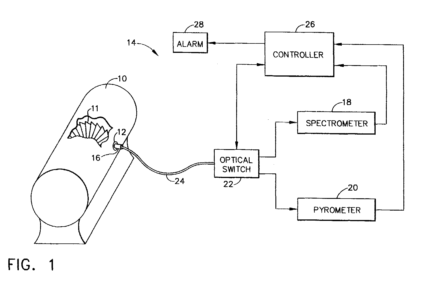
- Figure 1 schematically shows a gas turbine engine 10 having a plurality of turbine buckets 11 mounted internally for rotation about the engine's centerline axis.
- the gas turbine engine 10 has a sight glass 12 formed in its outer casing wall for providing optical access to the interior thereof.
- An optical system 14 is provided for measuring and monitoring the temperature of the turbine buckets 11.
- the system 14 includes an optical head 16 mounted on the sight glass 12, a spectrometer 18, a pyrometer 20, and an optical switch 22 for selectively directing radiation transmitted through the sight glass 12 to either one of the spectrometer 18 or the pyrometer 20.
- the optical head 16 is a conventional element that focuses the line of sight of the optical switch 22 onto the turbine buckets 11.
- a fiber optic cable 24 is provided for transmitting radiation from the optical head 16 to the optical switch 22.
- the system 14 is able to deliver radiation from the turbine buckets 11 to both the spectrometer 18 and the pyrometer 20, along the same line of sight.
- the spectrometer 18 measures the intensities at the various wavelengths of the radiation impinging thereon and generates an electrical signal representative of the resultant waveform.
- the pyrometer 20 generates an electrical signal proportional to the intensity of the radiation falling on it. This signal is indicative of the temperature of the turbine buckets 11 because the intensity of radiant energy emitted from the buckets 11 is a function of their temperature.
- Both the spectrometer signal and the pyrometer signal are fed to a controller 26.
- the pyrometer signal is used for relative bucket temperatures, and the spectrometer signal is used for absolute bucket temperatures. By comparing the two signals, the controller 26 is able to accurately determine the bucket temperature even if the sight glass 12 becomes clouded due to exposure to high temperature gases in the engine 10, or if the bucket surfaces are gray bodies with unknown emissivity.
- the system 14 is able to continuously monitor the temperature of the turbine buckets 11. If the bucket temperature exceeds a predetermined level, the controller 26 sends a signal that triggers an alarm 28 to alert the operator of the engine 10 of an impending problem.
- the controller 26 also controls the positioning of the optical switch 22 as it switches back and forth between the spectrometer 18 and the pyrometer 20. It should be noted that the controller 26 could be located on-site or remote from the gas turbine engine 10. For instance, the optical switch 22 could be remotely controlled from a desktop computer through a telephone line, network, or other transmission means.
- the system 14 has been described as employing the spectrometer 18 and the pyrometer 20, it should be noted that different types of detectors could also be used. Furthermore, more than two detectors can be used, as will become apparent from the following description of the optical switch 22.
- the switch 22 includes a rotor assembly 30 rotatively mounted between first and second blocks 32 and 34 disposed within a closed housing 36.
- the housing 36 encloses all of the other components to prevent contamination thereof.
- the first and second blocks 32 and 34 are fixedly secured to the housing 36 via conventional fasteners 37.
- the first block 32 is located near the front of the housing 36
- the second block 34 is located near the rear of the housing 36.
- the front or forward end of the optical switch 22 refers the end of the switch 22 in which input from the optical head 16 is received via the fiber optic cable 24.
- the front of the optical switch 22 is shown on the left in Figures 2 and 3.
- the rear of the optical switch 22 (or any element thereof) is shown on the right in Figures 2 and 3. As will been seen below, this is the end of the switch 22 at which optical detectors are provided to collect data that is output to the controller 26.
- the rotor assembly 30 includes a rotor 31 that comprises a rotor shaft 38 and a forward hub 40 attached to the forward end of the rotor shaft 38.
- the rotor 31 could alternatively be of a single piece construction.
- the rotor shaft 38 comprises a substantially cylindrical section 42 having a mounting flange 44 formed on its forward end and a trunnion 46 formed on its rear end.
- the trunnion 46 extends outwardly along the longitudinal axis defined by the cylindrical section 42.
- a central axial bore 48 is formed in the forward end of the rotor shaft 38 and extends nearly the entire length thereof.
- a lengthwise extending slot 50 is formed in the cylindrical section 42 so as to provide access to the axial bore 48.
- the forward hub 40 has a substantially cylindrical section 52 and a mounting flange 54 formed on its rear end.
- the mounting flanges 44 and 54 are fixedly secured by conventional means so that the rotor shaft 38 and forward hub 40 (i.e., the rotor 31) will rotate in unison.
- the longitudinal axis defined by the cylindrical section 52 coincides with the longitudinal axis of the cylindrical section 42 to define a single rotational axis for the rotor assembly 30.
- the forward hub 40 includes a central axial bore 56 extending through the entire length thereof. As shown in Figure 3, the axial bore 56 is counter-sunk so as to have a smaller diameter forward portion and a larger diameter rear portion.
- the cylindrical section 52 of the forward hub 40 is rotatively received in a bearing 58 formed in the rear surface of the first block 32 so that the rotor assembly 30 can rotate with respect to the first and second blocks 32 and 34 about its rotational axis.
- the trunnion 46 is rotatively received in a bearing 60 formed in the front surface of the second block 34.
- Rotation of the rotor assembly 30 is effectuated by a motor 62 mounted to the top of the first block 32.
- the motor 62 which is preferably, but not necessarily, a 12-volt DC gearbox motor, has a shaft 64 that can be selectively rotated in either a clockwise or counterclockwise direction.
- a drive gear 66 is fixedly mounted on the shaft 64 and engages a rotor gear 68 that is fixedly mounted on the cylindrical portion 52 of the forward hub 40, between the rear surface of the first block 32 and the mounting flange 54.
- the motor 62 rotates the drive gear 66, as dictated by input from the controller 26, the rotation is transmitted to the rotor assembly 30 via the rotor gear 68.
- the rotor assembly 30 includes a positioning disk 70 fixedly mounted on the trunnion 46 of the rotor shaft 38 for rotation therewith, adjacent to the front surface of the second block 34.
- the positioning disk 70 has a central bore in which the trunnion 46 is received so as to be mounted concentrically with respect to the rotor shaft 38.
- An offset hole 72 is formed in the positioning disk 70 at a distance from the center of the positioning disk 70.
- the positioning disk 70 also has four trip steps 74 equally spaced about its outer circumferential edge, the purpose of which is described below.
- the rotor assembly 30 further includes a second fiber optic cable 76 having first end located in the forward end of the axial bore 56 of the forward hub 40.
- the second fiber optic cable 76 extends rearward through the axial bore 56, into the axial bore 48 of the rotor shaft 36, and through the shaft slot 50.
- the second end of the second fiber optic cable 76 is disposed in the offset hole 72 of the positioning disk 70.
- the first end of the second fiber optic cable 76 is located on the rotational axis of the rotor assembly 30, and the second end of the second fiber optic cable 76 is offset from the rotational axis.
- the first end of the second fiber optic cable 76 is retained by a grommet 78 snugly received in the smaller diameter forward portion of the bore 56.
- the second end of the second fiber optic cable 76 is retained in the offset hole 72 by a grommet 80 snugly received therein.
- the first end of the second fiber optic cable 76 is aligned with, or even contacting, a corresponding end of the first fiber optic cable 24. It may also be equipped with optical devices, known in the art, to maximize the optical coupling between the second fiber optic cable 76 and the incoming fiber optic cable 24.
- the end of the first fiber optic cable 24 is fixed in the optical switch 22 by an adapter 82 disposed in a bore 84 formed in the forward surface of the first block 32.
- the adapter 82 is aligned with the bearing 58 so as to be aligned with the rotational axis of the rotor assembly 30.
- the end of the first fiber optic cable 24 is retained by a grommet 86 received in the adapter 82.
- the second block 34 has four detector holes 88 formed therein for receiving various optical detectors 90.
- the four detector holes 88 are equally spaced 90 degrees apart with respect to the bearing 60 formed in the second block 34.
- the four holes 88 are all located the same radial distance from the rotational axis of the rotor assembly 30, which distance is equal to the radial distance that the offset hole 72 is located from the rotational axis.
- the offset hole 72 and the second end of the second fiber optic cable 76 can be positioned adjacent to any one of the four holes 88 and the optical detector 90 disposed therein.
- the output from each of the optical detectors 90 is fed to the controller 26 as shown in Figure 3.
- the optical detectors 90 could comprise the spectrometer 18 and the pyrometer 20 described above with respect to Figure 1. However, although the system 14 of Figure 1 is one preferred application of the optical switch 22, the switch 22 could be used in many other applications. Thus, the detectors 90 are not limited to the spectrometer 18 and the pyrometer 20 and other types of detectors could be utilized. Furthermore, the optical switch 22 is not limited to four detectors 90, as the second block 34 could be provided with fewer or more of the detector holes 88. In which case, the positioning disk 70 would preferably be provided with a corresponding lesser or greater number of trip steps 74.
- a proximity sensor 92 is mounted on the second block 34 to provide position feedback to the controller 26 so that the second end of the second fiber optic cable 76 can be selectively positioned adjacent to the desired one of the detectors 90.
- the proximity sensor 92 is a capacitance-type proximity sensor mounted to the second block 34 via a plate 94.
- An electrode 96 is attached to the plate 94 so as to have one end located very close to, but not contacting, the outer circumferential edge of the positioning disk 70.
- the electrode 96 and the positioning disk 70 function as the two plates of a capacitor and a signal is generated.
- This signal is fed to the controller 26 so that the rotor position is known.
- the trip steps 74 are situated about the circumference of the positioning disk 70 such that the offset hole 72 will be aligned with one of the detector holes 88 whenever one of the trip steps 74 passes the electrode 96.
- the proximity sensor 92 provides positioning feedback to the controller 26 that allows the controller 26 to index the rotor assembly 30 to position the second end of the second fiber optic cable 76 adjacent to the desired one of the detectors 90.
- the second end of the second fiber optic cable 76 is positioned adjacent to a selected one of the optical detectors as determined by the control algorithm of the controller 26. Specifically, the controller 26 sends a signal to the motor 62, which causes the rotor assembly to rotate via the gears 66 and 68. When the appropriate trip step 74 moves into proximity with the electrode 96 of the proximity sensor 92, a signal is sent to the controller 26 that causes the controller 26 to stop rotation of the rotor assembly 30. With the rotor assembly in position, radiation from the optical head 16 is transmitted through the first fiber optic cable 24 to the first end of the second fiber optic cable 76. The radiation is then transmitted through the second fiber optic cable 76 and directed onto the selected one of the optical detectors 90. In response to the incident radiation, the selected optical detector sends an appropriate signal to the controller 26, as shown in Figure 3.
- the controller 26 sends another signal to the motor 26.
- the motor 26 causes the rotor assembly 30 to rotate again and position the second end of the second fiber optic cable 76 adjacent to the other optical detector 90. Radiation from the optical head 16 will now be directed onto the other optical detector 90, and the detector will generate a corresponding signal that is fed to the controller 26. The operation is the same for any other of the optical detectors 90.
- the optical switch 22 allows a plurality of optical detectors 90 to monitor a subject such as a turbine bucket 11 along the same line of sight.
- Using a common line of sight means that all of the optical detectors are looking at the same reference location on the buckets 11 and ensures that a valid comparison can be made between the outputs of the various detectors 90.
Landscapes
- Physics & Mathematics (AREA)
- General Physics & Mathematics (AREA)
- Spectroscopy & Molecular Physics (AREA)
- Optics & Photonics (AREA)
- Radiation Pyrometers (AREA)
- Investigating Or Analysing Materials By Optical Means (AREA)
- Mechanical Light Control Or Optical Switches (AREA)
Abstract
Description
- This invention relates generally to temperature measuring systems and more particularly to optical switches used in such systems.
- A gas turbine engine includes a compressor that provides pressurized air to a combustion section where the pressurized air is mixed with fuel and burned for generating hot combustion gases. These gases flow downstream to a multi-stage turbine. Each turbine stage includes a plurality of circumferentially spaced apart blades or buckets extending radially outwardly from a wheel that is fastened to a shaft for rotation about the centerline axis of the engine. The hot gases expand against the turbine buckets causing the wheel to rotate. This in turn rotates the shaft that is connected to the compressor and may be also connected to load equipment such as an electric generator or a gearbox. Thus, the turbine extracts energy from the hot gases to drive the compressor and provide useful work such as generating electricity or propelling an aircraft in flight.
- It is well known that the efficiency of gas turbine engines can be increased by raising the turbine operating temperature. As operating temperatures are increased, the thermal limits of certain engine components, such as the turbine buckets, may be exceeded, resulting in reduced service life or even material failure. In addition, the increased thermal expansion and contraction of these components adversely affects clearances and their interfitting relationship with other components. Thus, it is desirable to monitor the temperature of turbine buckets during engine operation to assure that they do not exceed their maximum rated temperature for an appreciable period of time.
- A common approach to monitoring turbine bucket temperature is to measure the temperature of the gas leaving the turbine and to use this as an indication of the bucket temperature. The turbine exit temperature can be measured by locating one or more temperature sensors, such as thermocouples, in the exhaust stream. Because the bucket temperature is measured indirectly, it is relatively inaccurate. Thus, it does not permit optimum bucket temperatures to be utilized because a wide safety margin must be maintained.
- The drawbacks of indirect bucket temperature measurement are well known, and approaches for measuring bucket temperatures directly have been proposed. One direct measurement approach uses a radiation pyrometer located outside of the engine casing and having a field of view focused on the turbine buckets through a sight glass formed in the casing wall. Radiation emitted by the heated turbine buckets thus impinges on the pyrometer that then generates an electrical signal representative of the bucket temperature. However, during engine operation the sight glass is exposed to high temperature exhaust gases that tend to cloud the sight glass and adversely affect the pyrometer reading. Furthermore, the optical emissivity of the bucket surfaces is usually unknown, which also introduces error into the temperature measurement.
- Accordingly, it would be desirable to have an approach to monitoring turbine bucket temperature that remotely monitored bucket temperature through the available sight glass, while avoiding the problems of limited optical access, impaired sight glasses, and unknown surface characteristics.
- The above-mentioned need is met by the present invention, which provides a system for measuring bucket temperature that includes a plurality of optical detectors, such as a pyrometer and a spectrometer, and an optical switch for selectively directing radiation from turbine engine sight glass to any one of the optical detectors along a common line of sight.
- In one preferred embodiment, the optical switch includes first and second blocks, with the optical detectors being disposed in the second block. A rotor is mounted between the first and second blocks for rotation about a rotational axis, and a fiber optic cable having a first end located on the rotational axis and a second end offset from the rotational axis is provided. Rotation of the rotor selectively positions the second end of the fiber optic cable adjacent to any one of the optical detectors.
- The present invention and its advantages over the prior art will become apparent upon reading the following detailed description and the appended claims with reference to the accompanying drawings.
- The invention will now be described in greater detail, by way of example, with reference to the drawings, in which:-
- Figure 1 is a schematic view of one embodiment of a temperature monitoring system having an optical switch.
- Figure 2 is cross-sectional top view of the optical switch of Figure 1.
- Figure 3 is cross-sectional side view of the optical switch of Figure 1.
- Figure 4 is a cross-sectional view of the optical switch taken along line 4-4 of Figure 3.
- Figure 5 is a cross-sectional view of the optical switch taken along line 5-5 of Figure 3.
-
- Referring to the drawings wherein identical reference numerals denote the same elements throughout the various views, Figure 1 schematically shows a
gas turbine engine 10 having a plurality ofturbine buckets 11 mounted internally for rotation about the engine's centerline axis. As is known in the art, thegas turbine engine 10 has asight glass 12 formed in its outer casing wall for providing optical access to the interior thereof. Anoptical system 14 is provided for measuring and monitoring the temperature of theturbine buckets 11. Thesystem 14 includes anoptical head 16 mounted on thesight glass 12, aspectrometer 18, apyrometer 20, and anoptical switch 22 for selectively directing radiation transmitted through thesight glass 12 to either one of thespectrometer 18 or thepyrometer 20. Theoptical head 16 is a conventional element that focuses the line of sight of theoptical switch 22 onto theturbine buckets 11. A fiberoptic cable 24 is provided for transmitting radiation from theoptical head 16 to theoptical switch 22. - With this arrangement, the
system 14 is able to deliver radiation from theturbine buckets 11 to both thespectrometer 18 and thepyrometer 20, along the same line of sight. Thespectrometer 18 measures the intensities at the various wavelengths of the radiation impinging thereon and generates an electrical signal representative of the resultant waveform. Thepyrometer 20 generates an electrical signal proportional to the intensity of the radiation falling on it. This signal is indicative of the temperature of theturbine buckets 11 because the intensity of radiant energy emitted from thebuckets 11 is a function of their temperature. Both the spectrometer signal and the pyrometer signal are fed to acontroller 26. The pyrometer signal is used for relative bucket temperatures, and the spectrometer signal is used for absolute bucket temperatures. By comparing the two signals, thecontroller 26 is able to accurately determine the bucket temperature even if thesight glass 12 becomes clouded due to exposure to high temperature gases in theengine 10, or if the bucket surfaces are gray bodies with unknown emissivity. - Thus, the
system 14 is able to continuously monitor the temperature of theturbine buckets 11. If the bucket temperature exceeds a predetermined level, thecontroller 26 sends a signal that triggers analarm 28 to alert the operator of theengine 10 of an impending problem. Thecontroller 26 also controls the positioning of theoptical switch 22 as it switches back and forth between thespectrometer 18 and thepyrometer 20. It should be noted that thecontroller 26 could be located on-site or remote from thegas turbine engine 10. For instance, theoptical switch 22 could be remotely controlled from a desktop computer through a telephone line, network, or other transmission means. Although thesystem 14 has been described as employing thespectrometer 18 and thepyrometer 20, it should be noted that different types of detectors could also be used. Furthermore, more than two detectors can be used, as will become apparent from the following description of theoptical switch 22. - Referring now to Figures 2-5, the
optical switch 22 is shown in more detail. Theswitch 22 includes arotor assembly 30 rotatively mounted between first andsecond blocks housing 36. Thehousing 36 encloses all of the other components to prevent contamination thereof. The first andsecond blocks housing 36 viaconventional fasteners 37. Thefirst block 32 is located near the front of thehousing 36, and thesecond block 34 is located near the rear of thehousing 36. As used herein, the front or forward end of the optical switch 22 (or any element thereof) refers the end of theswitch 22 in which input from theoptical head 16 is received via the fiberoptic cable 24. The front of theoptical switch 22 is shown on the left in Figures 2 and 3. Conversely, the rear of the optical switch 22 (or any element thereof) is shown on the right in Figures 2 and 3. As will been seen below, this is the end of theswitch 22 at which optical detectors are provided to collect data that is output to thecontroller 26. - The
rotor assembly 30 includes arotor 31 that comprises arotor shaft 38 and aforward hub 40 attached to the forward end of therotor shaft 38. Therotor 31 could alternatively be of a single piece construction. Therotor shaft 38 comprises a substantiallycylindrical section 42 having amounting flange 44 formed on its forward end and atrunnion 46 formed on its rear end. Thetrunnion 46 extends outwardly along the longitudinal axis defined by thecylindrical section 42. A central axial bore 48 is formed in the forward end of therotor shaft 38 and extends nearly the entire length thereof. A lengthwise extendingslot 50 is formed in thecylindrical section 42 so as to provide access to theaxial bore 48. Theforward hub 40 has a substantiallycylindrical section 52 and a mountingflange 54 formed on its rear end. The mountingflanges rotor shaft 38 and forward hub 40 (i.e., the rotor 31) will rotate in unison. The longitudinal axis defined by thecylindrical section 52 coincides with the longitudinal axis of thecylindrical section 42 to define a single rotational axis for therotor assembly 30. Theforward hub 40 includes a central axial bore 56 extending through the entire length thereof. As shown in Figure 3, theaxial bore 56 is counter-sunk so as to have a smaller diameter forward portion and a larger diameter rear portion. - The
cylindrical section 52 of theforward hub 40 is rotatively received in abearing 58 formed in the rear surface of thefirst block 32 so that therotor assembly 30 can rotate with respect to the first andsecond blocks trunnion 46 is rotatively received in abearing 60 formed in the front surface of thesecond block 34. Rotation of therotor assembly 30 is effectuated by amotor 62 mounted to the top of thefirst block 32. Themotor 62, which is preferably, but not necessarily, a 12-volt DC gearbox motor, has ashaft 64 that can be selectively rotated in either a clockwise or counterclockwise direction. Adrive gear 66 is fixedly mounted on theshaft 64 and engages arotor gear 68 that is fixedly mounted on thecylindrical portion 52 of theforward hub 40, between the rear surface of thefirst block 32 and the mountingflange 54. Thus, when themotor 62 rotates thedrive gear 66, as dictated by input from thecontroller 26, the rotation is transmitted to therotor assembly 30 via therotor gear 68. - The
rotor assembly 30 includes apositioning disk 70 fixedly mounted on thetrunnion 46 of therotor shaft 38 for rotation therewith, adjacent to the front surface of thesecond block 34. Specifically, thepositioning disk 70 has a central bore in which thetrunnion 46 is received so as to be mounted concentrically with respect to therotor shaft 38. An offsethole 72 is formed in thepositioning disk 70 at a distance from the center of thepositioning disk 70. Thepositioning disk 70 also has fourtrip steps 74 equally spaced about its outer circumferential edge, the purpose of which is described below. - The
rotor assembly 30 further includes a secondfiber optic cable 76 having first end located in the forward end of theaxial bore 56 of theforward hub 40. The secondfiber optic cable 76 extends rearward through theaxial bore 56, into theaxial bore 48 of therotor shaft 36, and through theshaft slot 50. The second end of the secondfiber optic cable 76 is disposed in the offsethole 72 of thepositioning disk 70. Thus, the first end of the secondfiber optic cable 76 is located on the rotational axis of therotor assembly 30, and the second end of the secondfiber optic cable 76 is offset from the rotational axis. The first end of the secondfiber optic cable 76 is retained by agrommet 78 snugly received in the smaller diameter forward portion of thebore 56. The second end of the secondfiber optic cable 76 is retained in the offsethole 72 by agrommet 80 snugly received therein. - The first end of the second
fiber optic cable 76 is aligned with, or even contacting, a corresponding end of the firstfiber optic cable 24. It may also be equipped with optical devices, known in the art, to maximize the optical coupling between the secondfiber optic cable 76 and the incomingfiber optic cable 24. The end of the firstfiber optic cable 24 is fixed in theoptical switch 22 by anadapter 82 disposed in abore 84 formed in the forward surface of thefirst block 32. Theadapter 82 is aligned with the bearing 58 so as to be aligned with the rotational axis of therotor assembly 30. The end of the firstfiber optic cable 24 is retained by agrommet 86 received in theadapter 82. - The
second block 34 has fourdetector holes 88 formed therein for receiving variousoptical detectors 90. As best seen in Figure 4, the fourdetector holes 88 are equally spaced 90 degrees apart with respect to thebearing 60 formed in thesecond block 34. The fourholes 88 are all located the same radial distance from the rotational axis of therotor assembly 30, which distance is equal to the radial distance that the offsethole 72 is located from the rotational axis. Thus, by rotating therotor assembly 30, the offsethole 72 and the second end of the secondfiber optic cable 76 can be positioned adjacent to any one of the fourholes 88 and theoptical detector 90 disposed therein. The output from each of theoptical detectors 90 is fed to thecontroller 26 as shown in Figure 3. - The
optical detectors 90 could comprise thespectrometer 18 and thepyrometer 20 described above with respect to Figure 1. However, although thesystem 14 of Figure 1 is one preferred application of theoptical switch 22, theswitch 22 could be used in many other applications. Thus, thedetectors 90 are not limited to thespectrometer 18 and thepyrometer 20 and other types of detectors could be utilized. Furthermore, theoptical switch 22 is not limited to fourdetectors 90, as thesecond block 34 could be provided with fewer or more of the detector holes 88. In which case, thepositioning disk 70 would preferably be provided with a corresponding lesser or greater number of trip steps 74. - A
proximity sensor 92 is mounted on thesecond block 34 to provide position feedback to thecontroller 26 so that the second end of the secondfiber optic cable 76 can be selectively positioned adjacent to the desired one of thedetectors 90. In one preferred embodiment, best seen in Figure 5, theproximity sensor 92 is a capacitance-type proximity sensor mounted to thesecond block 34 via aplate 94. Anelectrode 96 is attached to theplate 94 so as to have one end located very close to, but not contacting, the outer circumferential edge of thepositioning disk 70. When one of the trip steps 74 passes theelectrode 96 as therotor assembly 30 rotates, the gap between theelectrode 96 and thepositioning disk 70 becomes very small. At this point, theelectrode 96 and thepositioning disk 70 function as the two plates of a capacitor and a signal is generated. This signal is fed to thecontroller 26 so that the rotor position is known. The trip steps 74 are situated about the circumference of thepositioning disk 70 such that the offsethole 72 will be aligned with one of the detector holes 88 whenever one of the trip steps 74 passes theelectrode 96. Thus, theproximity sensor 92 provides positioning feedback to thecontroller 26 that allows thecontroller 26 to index therotor assembly 30 to position the second end of the secondfiber optic cable 76 adjacent to the desired one of thedetectors 90. - In operation, the second end of the second
fiber optic cable 76 is positioned adjacent to a selected one of the optical detectors as determined by the control algorithm of thecontroller 26. Specifically, thecontroller 26 sends a signal to themotor 62, which causes the rotor assembly to rotate via thegears appropriate trip step 74 moves into proximity with theelectrode 96 of theproximity sensor 92, a signal is sent to thecontroller 26 that causes thecontroller 26 to stop rotation of therotor assembly 30. With the rotor assembly in position, radiation from theoptical head 16 is transmitted through the firstfiber optic cable 24 to the first end of the secondfiber optic cable 76. The radiation is then transmitted through the secondfiber optic cable 76 and directed onto the selected one of theoptical detectors 90. In response to the incident radiation, the selected optical detector sends an appropriate signal to thecontroller 26, as shown in Figure 3. - When data from another one of the
optical detectors 90 is required, thecontroller 26 sends another signal to themotor 26. In response to this signal, themotor 26 causes therotor assembly 30 to rotate again and position the second end of the secondfiber optic cable 76 adjacent to the otheroptical detector 90. Radiation from theoptical head 16 will now be directed onto the otheroptical detector 90, and the detector will generate a corresponding signal that is fed to thecontroller 26. The operation is the same for any other of theoptical detectors 90. - Thus, the
optical switch 22 allows a plurality ofoptical detectors 90 to monitor a subject such as aturbine bucket 11 along the same line of sight. Using a common line of sight means that all of the optical detectors are looking at the same reference location on thebuckets 11 and ensures that a valid comparison can be made between the outputs of thevarious detectors 90. - For the sake of good order, various aspects of the invention are set out in the following clauses:-
- 1. A temperature measuring system comprising:
- at least two optical detectors; and
- means for selectively directing radiation to either one of said at least two optical detectors along a common line of sight.
- 2. The temperature measuring system of clause 1 wherein said at least two optical detectors comprise a pyrometer and a spectrometer.
- 3. The temperature measuring system of clause 1 wherein said means for selectively directing radiation comprises an optical switch.
- 4. The temperature measuring system of clause 3 wherein said optical
switch comprises:
- first and second blocks, said optical detectors being disposed in said second block;
- a rotor rotatively mounted between said first and second blocks about a rotational axis; and
- a fiber optic cable having a first end located on said rotational axis and a second end offset from said rotational axis, wherein rotation of said rotor selectively positions said second end of said fiber optic cable adjacent to any one of said optical detectors.
- 5. The temperature measuring system of
clause 4 wherein each one of said optical detectors is located an equal distance from said rotational axis. - 6. The temperature measuring system of
clause 5 wherein said second end of said fiber optic cable is offset from said rotational axis an equal distance as said optical detectors. - 7. The temperature measuring system of
clause 4 further comprising a disk mounted on said rotor, wherein said second end of said fiber optic cable is located in a hole formed in said disk. - 8. The temperature measuring system of clause 7 wherein said first end of said fiber optic cable is located in a bore formed in one end of said rotor.
- 9. The temperature measuring system of clause 8 wherein said fiber optic cable extends through a slot formed in said rotor.
- 10. The temperature measuring system of clause 7 further comprising a proximity sensor located adjacent to said disk.
- 11. The temperature measuring system of
clause 10 further comprising a plurality of trip steps formed on said disk. - 12. The temperature measuring system of
clause 4 further comprising a motor for rotating said rotor. - 13. The temperature measuring system of
clause 12 further comprising a first gear driven by said motor and a second gear mounted on said rotor, said first gear engaging said second gear. - 14. The temperature measuring system of
clause 4 further comprising a housing enclosing said first and second blocks and said rotor. - 15. A system for measuring bucket temperature in a gas turbine engine
having a sight glass, said system comprising:
- a pyrometer;
- a spectrometer; and
- an optical switch for selectively directing radiation from said sight glass to either one of said pyrometer or said spectrometer along a common line of sight.
- 16. The system of clause 15 further comprising a fiber optic cable extending between said sight glass and said optical switch.
- 17. The system of clause 15 wherein said optical switch comprises:
- first and second blocks, said pyrometer and said spectrometer being disposed in said second block;
- a rotor rotatively mounted between said first and second blocks about a rotational axis; and
- a fiber optic cable having a first end located on said rotational axis and a second end offset from said rotational axis, wherein rotation of said rotor selectively positions said second end of said fiber optic cable adjacent to either one of said pyrometer or said spectrometer.
- 18. The system of clause 17 wherein said pyrometer and said spectrometer are located equal distances from said rotational axis.
- 19. The system of
clause 18 wherein said second end of said fiber optic cable is offset from said rotational axis an equal distance as said pyrometer and said spectrometer. - 20. The system of clause 17 further comprising a disk mounted on said rotor, wherein said second end of said fiber optic cable is located in a hole formed in said disk.
- 21. The system of
clause 20 wherein said first end of said fiber optic cable is located in a bore formed in one end of said rotor. - 22. The system of clause 21 wherein said fiber optic cable extends through a slot formed in said rotor.
- 23. The system of
clause 20 further comprising a proximity sensor located adjacent to said disk. - 24. The system of clause 23 further comprising a plurality of trip steps formed on said disk.
- 25. The system of clause 17 further comprising a motor for rotating said rotor.
- 26. The system of clause 25 further comprising a first gear driven by said motor and a second gear mounted on said rotor, said first gear engaging said second gear.
- 27. The system of clause 17 further comprising a housing enclosing said first and second blocks and said rotor.
- 28. An optical switch comprising:
- first and second blocks;
- a rotor rotatively mounted between said first and second blocks about a rotational axis;
- a plurality of optical detectors disposed in said second block; and
- a fiber optic cable having a first end located on said rotational axis and a second end offset from said rotational axis, wherein rotation of said rotor selectively positions said second end of said fiber optic cable adjacent to one of said optical detectors.
- 29. The optical switch of
clause 28 wherein each one of said optical detectors is located an equal distance from said rotational axis. - 30. The optical switch of clause 29 wherein said second end of said fiber optic cable is offset from said rotational axis an equal distance as said optical detectors.
- 31. The optical switch of
clause 28 further comprising a disk mounted on said rotor, wherein said second end of said fiber optic cable is located in a hole formed in said disk. - 32. The optical switch of
clause 31 wherein said first end of said fiber optic cable is located in a bore formed in one end of said rotor. - 33. The optical switch of
clause 32 wherein said fiber optic cable extends through a slot formed in said rotor. - 34. The optical switch of
clause 31 further comprising a proximity sensor located adjacent to said disk. - 35. The optical switch of
clause 34 further comprising a plurality of trip steps formed on said disk. - 36. The optical switch of
clause 28 further comprising a motor for rotating said rotor. - 37. The optical switch of
clause 36 further comprising a first gear driven by said motor and a second gear mounted on said rotor, said first gear engaging said second gear. - 38. The optical switch of
clause 28 further comprising a housing enclosing said first and second blocks and said rotor. -
Claims (13)
- A temperature measuring system (14) comprising:at least two optical detectors (18, 20); andmeans (22) for selectively directing radiation to either one of said at least two optical detectors (18, 20) along a common line of sight.
- The temperature measuring system (14) of claim 1 wherein said at least two optical detectors (18, 20) comprise a pyrometer (20) and a spectrometer (18).
- The temperature measuring system (14) of claim 1 wherein said means (22) for selectively directing radiation comprises an optical switch.
- The temperature measuring system (14) of claim 3 wherein said optical switch (22) comprises:first and second blocks (32, 34), said optical detectors (18, 20) being disposed in said second block (34);a rotor (31) rotatively mounted between said first and second blocks (32, 34) about a rotational axis; anda fiber optic cable (76) having a first end located on said rotational axis and a second end offset from said rotational axis, wherein rotation of said rotor (31) selectively positions said second end of said fiber optic cable (76) adjacent to any one of said optical detectors.
- The temperature measuring system (14) of claim 4 wherein each one of said optical detectors (18, 20) is located an equal distance from said rotational axis.
- The temperature measuring system (14) of claim 4 further comprising a disk (70) mounted on said rotor (31), wherein said second end of said fiber optic cable (76) is located in a hole (72) formed in said disk (70).
- The temperature measuring system (14) of claim 4 further comprising a motor (62) for rotating said rotor (31).
- A system (14) for measuring bucket temperature in a gas turbine engine (10) having a sight glass (12), said system (14) comprising:a pyrometer (20);a spectrometer (18); andan optical switch (22) for selectively directing radiation from said sight glass (12) to either one of said pyrometer (20) or said spectrometer (18) along a common line of sight.
- The system (14) of claim 8 further comprising a fiber optic cable (24) extending between said sight glass (12) and said optical switch (22).
- The system (14) of claim 8 wherein said optical switch (22) comprises:first and second blocks (32, 34), said pyrometer (20)and said spectrometer (18) being disposed in said second block (34);a rotor (31) rotatively mounted between said first and second blocks (32, 34) about a rotational axis; anda fiber optic cable (76) having a first end located on said rotational axis and a second end offset from said rotational axis, wherein rotation of said rotor (31) selectively positions said second end of said fiber optic cable (76) adjacent to either one of said pyrometer (20) or said spectrometer (18).
- The system (14) of claim 10 wherein said pyrometer (20) and said spectrometer (18) are located equal distances from said rotational axis.
- The system (14) of claim 10 further comprising a disk (70) mounted on said rotor (31), wherein said second end of said fiber optic cable (76) is located in a hole (72) formed in said disk (70).
- The system (14) of claim 10 further comprising a motor (62) for rotating said rotor (31).
Applications Claiming Priority (2)
| Application Number | Priority Date | Filing Date | Title |
|---|---|---|---|
| US566942 | 2000-05-08 | ||
| US09/566,942 US6698920B1 (en) | 2000-05-08 | 2000-05-08 | Temperature measuring system and optical switch used therein |
Publications (2)
| Publication Number | Publication Date |
|---|---|
| EP1154252A1 true EP1154252A1 (en) | 2001-11-14 |
| EP1154252B1 EP1154252B1 (en) | 2006-10-11 |
Family
ID=24265080
Family Applications (1)
| Application Number | Title | Priority Date | Filing Date |
|---|---|---|---|
| EP01304102A Expired - Lifetime EP1154252B1 (en) | 2000-05-08 | 2001-05-04 | Temperature measuring system and optical switch used therein |
Country Status (6)
| Country | Link |
|---|---|
| US (1) | US6698920B1 (en) |
| EP (1) | EP1154252B1 (en) |
| JP (1) | JP2002071465A (en) |
| KR (1) | KR100694372B1 (en) |
| CZ (1) | CZ2001370A3 (en) |
| DE (1) | DE60123700T2 (en) |
Cited By (2)
| Publication number | Priority date | Publication date | Assignee | Title |
|---|---|---|---|---|
| WO2003087901A3 (en) * | 2002-02-14 | 2004-05-06 | Varian Inc | Fiber-optic channel selecting apparatus |
| EP2447687A1 (en) * | 2010-10-28 | 2012-05-02 | General Electric Company | Smart radiation thermometry system for real time gas turbine control and prognosis |
Families Citing this family (18)
| Publication number | Priority date | Publication date | Assignee | Title |
|---|---|---|---|---|
| GB2371358A (en) * | 2001-01-22 | 2002-07-24 | Optokem Ltd | Light scattering particle characterisation apparatus and detection means |
| US6950568B2 (en) * | 2002-02-14 | 2005-09-27 | Varian, Inc. | Fiber-optic channel selecting apparatus |
| US20040179575A1 (en) * | 2003-01-23 | 2004-09-16 | Markham James R. | Instrument for temperature and condition monitoring of advanced turbine blades |
| US7633066B2 (en) * | 2006-05-22 | 2009-12-15 | General Electric Company | Multiwavelength pyrometry systems |
| US7675618B2 (en) * | 2007-04-16 | 2010-03-09 | Ase Optics, Inc. | Multiplexing spectrometer |
| US20090232448A1 (en) * | 2008-03-14 | 2009-09-17 | Eci Technology, Inc. | Fiber optic multiplexer |
| JP5284668B2 (en) * | 2008-03-31 | 2013-09-11 | 株式会社Ihi | Optical pyrometer |
| US8292501B1 (en) * | 2008-05-13 | 2012-10-23 | Florida Turbine Technologies, Inc. | Turbopump with cavitation detection |
| US20090285259A1 (en) * | 2008-05-14 | 2009-11-19 | General Electric Company | System and method for thermal inspection of objects |
| US8790006B2 (en) * | 2009-11-30 | 2014-07-29 | General Electric Company | Multiwavelength thermometer |
| US10132688B2 (en) | 2010-12-17 | 2018-11-20 | General Electric Company | System and method for detecting spall within a turbine engine |
| US20130079644A1 (en) * | 2011-09-23 | 2013-03-28 | Tyco Electronics Corporation | Optical Probe with Electric Motor |
| US9482596B2 (en) * | 2013-06-24 | 2016-11-01 | General Electric Company | Optical monitoring system for a gas turbine engine |
| AU2015205700B2 (en) * | 2014-01-08 | 2017-07-06 | Vesuvius Group, Sa | Optical pyrometer |
| DE102016010402A1 (en) | 2015-09-01 | 2017-03-02 | Sew-Eurodrive Gmbh & Co Kg | Arrangement for determining the surface temperature |
| EP3282235B1 (en) * | 2016-08-08 | 2019-04-17 | Ansaldo Energia Switzerland AG | Gas turbine power plant comprising a temperature detecting device |
| CN107100680B (en) * | 2017-06-19 | 2019-06-21 | 电子科技大学 | A device for light collection on the surface of turbine blades |
| CN112798140B (en) * | 2020-12-23 | 2024-07-19 | 成都伊莱特光测科技有限公司 | Water turbine set rotor signal extraction device and system based on optical fiber sensing |
Citations (7)
| Publication number | Priority date | Publication date | Assignee | Title |
|---|---|---|---|---|
| US4441785A (en) * | 1981-10-29 | 1984-04-10 | International Business Machines Corporation | Rotary fiber optic switch |
| US4568183A (en) * | 1982-07-15 | 1986-02-04 | Rolls-Royce Limited | Detection of changes in transparency of optical elements |
| US4648711A (en) * | 1984-06-08 | 1987-03-10 | The Dow Chemical Company | Sight tube assembly and sensing instrument for controlling a gas turbine |
| US4666297A (en) * | 1985-11-14 | 1987-05-19 | United Technologies Corporation | Dual spectra optical pyrometer having an air pressure sensitive shutter |
| US4942294A (en) * | 1988-05-12 | 1990-07-17 | General Electric Company | Fiber optic sensing apparatus for multiplexing a plurality of optical signals of different wavelengths over a single fiber optic cable |
| EP0379192A2 (en) * | 1989-01-19 | 1990-07-25 | Alcatel N.V. | Fiber optic switch |
| US5755510A (en) * | 1994-10-21 | 1998-05-26 | Societe Europeenne De Propulsionm | Fast bichromatic pyrometer for use with an optical fiber |
Family Cites Families (27)
| Publication number | Priority date | Publication date | Assignee | Title |
|---|---|---|---|---|
| US4118985A (en) | 1974-08-30 | 1978-10-10 | International Harvester Company | Radiation pyrometers |
| DE2704984A1 (en) * | 1977-02-07 | 1978-08-10 | Siemens Ag | SWITCH FOR FIBER OPERATING FIBERS |
| SU699352A1 (en) * | 1978-03-13 | 1979-11-25 | Предприятие П/Я В-2504 | Pyrometer for measuring the temperature of gas turbine blades |
| GB1602160A (en) * | 1978-04-26 | 1981-11-11 | Negretti & Zambra Aviat Ltd | Pyrometers |
| US4142417A (en) * | 1978-04-28 | 1979-03-06 | The United States Of America As Represented By The Secretary Of The Interior | Multichannel infrared pyrometer |
| US4239330A (en) * | 1978-10-18 | 1980-12-16 | Bell Telephone Laboratories, Incorporated | Multiple optical switch |
| US4378144A (en) * | 1980-12-22 | 1983-03-29 | Northern Telecom Limited | Optical switch |
| US4896935A (en) * | 1985-10-07 | 1990-01-30 | Lee Ho Shang | Fiber optic switch |
| US4657386A (en) * | 1985-11-14 | 1987-04-14 | United Technologies Corporation | In-flight engine control optical pyrometer |
| US4753501A (en) * | 1986-01-15 | 1988-06-28 | The United States Of America As Represented By The Secretary Of The Air Force | Fiber optic rotary switching device |
| JPS62201047A (en) * | 1986-02-28 | 1987-09-04 | Toshiba Corp | Brushless motor |
| US4790669A (en) * | 1986-04-08 | 1988-12-13 | Cv Technology, Inc. | Spectroscopic method and apparatus for optically measuring temperature |
| GB8629492D0 (en) * | 1986-12-10 | 1987-01-21 | Smiths Industries Plc | Optical radiation sensor apparatus |
| US4907895A (en) * | 1988-03-31 | 1990-03-13 | Ivac Corporation | Optical chopper for infrared thermometer |
| GB2235042B (en) * | 1989-07-29 | 1993-10-27 | Smiths Industries Plc | Sensing systems |
| JPH0377030A (en) * | 1989-08-21 | 1991-04-02 | Kawasaki Steel Corp | Reaction vapor phase monitor device |
| JPH0579624A (en) * | 1991-09-18 | 1993-03-30 | Babcock Hitachi Kk | Combustion diagnosing device |
| US5348396A (en) * | 1992-11-20 | 1994-09-20 | The United States Of America As Represented By The United States Department Of Energy | Method and apparatus for optical temperature measurement |
| US5292196A (en) * | 1993-02-17 | 1994-03-08 | Kawasaki Steel Corporation | Optical fiber type temperature distribution measuring apparatus |
| FR2703455B1 (en) * | 1993-04-01 | 1995-05-12 | Europ Gas Turbines Sa | Bichromatic pyrometer. |
| JP3161179B2 (en) * | 1993-09-20 | 2001-04-25 | 三菱自動車工業株式会社 | Ceramic turbine rotor breakdown detection device |
| US5408550A (en) * | 1994-03-09 | 1995-04-18 | Wireless Control System, Inc. | Remote fiber optic electrical switch using light pulse signals |
| US5664034A (en) * | 1996-05-21 | 1997-09-02 | Lucent Technologies Inc. | Lightwave communication monitoring switch |
| JPH10104084A (en) * | 1996-09-27 | 1998-04-24 | Mitsubishi Heavy Ind Ltd | Multicolor thermometer |
| SG74025A1 (en) * | 1997-10-03 | 2000-07-18 | Inst Of Microelectronics | Combined infrared and visible light spectroscopic photoemission microscope |
| US6031947A (en) * | 1998-06-05 | 2000-02-29 | Laor; Herzel | 1×N optical switch |
| WO2001063351A1 (en) * | 2000-02-22 | 2001-08-30 | Light Management Group Inc. | Acousto-optical switch for fiber optic lines |
-
2000
- 2000-05-08 US US09/566,942 patent/US6698920B1/en not_active Expired - Fee Related
-
2001
- 2001-01-30 CZ CZ2001370A patent/CZ2001370A3/en unknown
- 2001-05-04 EP EP01304102A patent/EP1154252B1/en not_active Expired - Lifetime
- 2001-05-04 KR KR1020010024243A patent/KR100694372B1/en not_active Expired - Fee Related
- 2001-05-04 DE DE60123700T patent/DE60123700T2/en not_active Expired - Lifetime
- 2001-05-07 JP JP2001135686A patent/JP2002071465A/en active Pending
Patent Citations (7)
| Publication number | Priority date | Publication date | Assignee | Title |
|---|---|---|---|---|
| US4441785A (en) * | 1981-10-29 | 1984-04-10 | International Business Machines Corporation | Rotary fiber optic switch |
| US4568183A (en) * | 1982-07-15 | 1986-02-04 | Rolls-Royce Limited | Detection of changes in transparency of optical elements |
| US4648711A (en) * | 1984-06-08 | 1987-03-10 | The Dow Chemical Company | Sight tube assembly and sensing instrument for controlling a gas turbine |
| US4666297A (en) * | 1985-11-14 | 1987-05-19 | United Technologies Corporation | Dual spectra optical pyrometer having an air pressure sensitive shutter |
| US4942294A (en) * | 1988-05-12 | 1990-07-17 | General Electric Company | Fiber optic sensing apparatus for multiplexing a plurality of optical signals of different wavelengths over a single fiber optic cable |
| EP0379192A2 (en) * | 1989-01-19 | 1990-07-25 | Alcatel N.V. | Fiber optic switch |
| US5755510A (en) * | 1994-10-21 | 1998-05-26 | Societe Europeenne De Propulsionm | Fast bichromatic pyrometer for use with an optical fiber |
Cited By (2)
| Publication number | Priority date | Publication date | Assignee | Title |
|---|---|---|---|---|
| WO2003087901A3 (en) * | 2002-02-14 | 2004-05-06 | Varian Inc | Fiber-optic channel selecting apparatus |
| EP2447687A1 (en) * | 2010-10-28 | 2012-05-02 | General Electric Company | Smart radiation thermometry system for real time gas turbine control and prognosis |
Also Published As
| Publication number | Publication date |
|---|---|
| DE60123700T2 (en) | 2007-08-30 |
| EP1154252B1 (en) | 2006-10-11 |
| JP2002071465A (en) | 2002-03-08 |
| KR100694372B1 (en) | 2007-03-12 |
| US6698920B1 (en) | 2004-03-02 |
| CZ2001370A3 (en) | 2001-12-12 |
| KR20010104648A (en) | 2001-11-26 |
| DE60123700D1 (en) | 2006-11-23 |
Similar Documents
| Publication | Publication Date | Title |
|---|---|---|
| EP1154252B1 (en) | Temperature measuring system and optical switch used therein | |
| US20090285259A1 (en) | System and method for thermal inspection of objects | |
| US8177483B2 (en) | Active casing alignment control system and method | |
| US5226731A (en) | Apparatus for measuring rotor exhaust gas bulk temperature in a combustion turbine and method therefor | |
| US6109783A (en) | Optic pyrometer for gas turbines | |
| AU564325B2 (en) | Optical pyrometer sight tube assembly for controlling a gas turbine | |
| KR101503669B1 (en) | A diagnostic system and method for monitoring operating conditions of components of a turbine machine | |
| US20100296912A1 (en) | Active Rotor Alignment Control System And Method | |
| JP2010502893A (en) | Electrical assembly for monitoring conditions in the operating environment of a combustion turbine | |
| US4037473A (en) | Radiation pyrometers with purging fluid | |
| EP2447687A1 (en) | Smart radiation thermometry system for real time gas turbine control and prognosis | |
| JP3488244B2 (en) | Passive sensor for monitoring gas turbine blade vibration | |
| US7633066B2 (en) | Multiwavelength pyrometry systems | |
| US6568091B1 (en) | Rotor component displacement measurement system | |
| US4870270A (en) | Fiber optic speed sensing for a rotating shaft | |
| EP4134643A1 (en) | Non-contact high temperature measurement system | |
| WO2017072254A1 (en) | System for sensing shifting of drive ring, compressor and gas turbine | |
| Rohy et al. | Radiation pyrometer for gas turbine blades | |
| CN115493702B (en) | Turbine blade radiation temperature measuring device and temperature measuring method thereof | |
| Miller et al. | Optical sensors for turbine engine applications | |
| JPH08191556A (en) | Rotor coil end monitor | |
| US12535015B2 (en) | Actively driven remote mount optical probe | |
| Tuma et al. | Flight tests on a fiber optic temperature sensor | |
| Eggert et al. | Development and evaluation of a high resolution turbine pyrometer system | |
| Schenk et al. | Fast Response Turbine Pyrometry for High Temperature Gas Turbine Applications-Present State of Technology and Future Demands |
Legal Events
| Date | Code | Title | Description |
|---|---|---|---|
| PUAI | Public reference made under article 153(3) epc to a published international application that has entered the european phase |
Free format text: ORIGINAL CODE: 0009012 |
|
| AK | Designated contracting states |
Kind code of ref document: A1 Designated state(s): CH DE FR IT LI NL SE Kind code of ref document: A1 Designated state(s): AT BE CH CY DE DK ES FI FR GB GR IE IT LI LU MC NL PT SE TR |
|
| AX | Request for extension of the european patent |
Free format text: AL;LT;LV;MK;RO;SI |
|
| 17P | Request for examination filed |
Effective date: 20020514 |
|
| AKX | Designation fees paid |
Free format text: CH DE FR IT LI NL SE |
|
| 17Q | First examination report despatched |
Effective date: 20040617 |
|
| GRAP | Despatch of communication of intention to grant a patent |
Free format text: ORIGINAL CODE: EPIDOSNIGR1 |
|
| GRAS | Grant fee paid |
Free format text: ORIGINAL CODE: EPIDOSNIGR3 |
|
| GRAA | (expected) grant |
Free format text: ORIGINAL CODE: 0009210 |
|
| AK | Designated contracting states |
Kind code of ref document: B1 Designated state(s): CH DE FR IT LI NL SE |
|
| PG25 | Lapsed in a contracting state [announced via postgrant information from national office to epo] |
Ref country code: IT Free format text: LAPSE BECAUSE OF FAILURE TO SUBMIT A TRANSLATION OF THE DESCRIPTION OR TO PAY THE FEE WITHIN THE PRESCRIBED TIME-LIMIT;WARNING: LAPSES OF ITALIAN PATENTS WITH EFFECTIVE DATE BEFORE 2007 MAY HAVE OCCURRED AT ANY TIME BEFORE 2007. THE CORRECT EFFECTIVE DATE MAY BE DIFFERENT FROM THE ONE RECORDED. Effective date: 20061011 |
|
| REG | Reference to a national code |
Ref country code: CH Ref legal event code: EP |
|
| REG | Reference to a national code |
Ref country code: CH Ref legal event code: NV Representative=s name: SERVOPATENT GMBH |
|
| REF | Corresponds to: |
Ref document number: 60123700 Country of ref document: DE Date of ref document: 20061123 Kind code of ref document: P |
|
| REG | Reference to a national code |
Ref country code: SE Ref legal event code: TRGR |
|
| ET | Fr: translation filed | ||
| PLBE | No opposition filed within time limit |
Free format text: ORIGINAL CODE: 0009261 |
|
| STAA | Information on the status of an ep patent application or granted ep patent |
Free format text: STATUS: NO OPPOSITION FILED WITHIN TIME LIMIT |
|
| 26N | No opposition filed |
Effective date: 20070712 |
|
| REG | Reference to a national code |
Ref country code: CH Ref legal event code: PFA Owner name: GENERAL ELECTRIC COMPANY Free format text: GENERAL ELECTRIC COMPANY#1 RIVER ROAD#SCHENECTADY, NY 12345 (US) -TRANSFER TO- GENERAL ELECTRIC COMPANY#1 RIVER ROAD#SCHENECTADY, NY 12345 (US) |
|
| PGFP | Annual fee paid to national office [announced via postgrant information from national office to epo] |
Ref country code: FR Payment date: 20110607 Year of fee payment: 11 Ref country code: SE Payment date: 20110527 Year of fee payment: 11 Ref country code: CH Payment date: 20110525 Year of fee payment: 11 |
|
| PGFP | Annual fee paid to national office [announced via postgrant information from national office to epo] |
Ref country code: NL Payment date: 20110531 Year of fee payment: 11 |
|
| PGFP | Annual fee paid to national office [announced via postgrant information from national office to epo] |
Ref country code: DE Payment date: 20110527 Year of fee payment: 11 Ref country code: IT Payment date: 20110525 Year of fee payment: 11 |
|
| REG | Reference to a national code |
Ref country code: NL Ref legal event code: V1 Effective date: 20121201 |
|
| REG | Reference to a national code |
Ref country code: CH Ref legal event code: PL |
|
| REG | Reference to a national code |
Ref country code: SE Ref legal event code: EUG |
|
| PG25 | Lapsed in a contracting state [announced via postgrant information from national office to epo] |
Ref country code: CH Free format text: LAPSE BECAUSE OF NON-PAYMENT OF DUE FEES Effective date: 20120531 Ref country code: LI Free format text: LAPSE BECAUSE OF NON-PAYMENT OF DUE FEES Effective date: 20120531 |
|
| PG25 | Lapsed in a contracting state [announced via postgrant information from national office to epo] |
Ref country code: SE Free format text: LAPSE BECAUSE OF NON-PAYMENT OF DUE FEES Effective date: 20120505 Ref country code: IT Free format text: LAPSE BECAUSE OF NON-PAYMENT OF DUE FEES Effective date: 20120504 |
|
| REG | Reference to a national code |
Ref country code: FR Ref legal event code: ST Effective date: 20130131 |
|
| REG | Reference to a national code |
Ref country code: DE Ref legal event code: R119 Ref document number: 60123700 Country of ref document: DE Effective date: 20121201 |
|
| PG25 | Lapsed in a contracting state [announced via postgrant information from national office to epo] |
Ref country code: NL Free format text: LAPSE BECAUSE OF NON-PAYMENT OF DUE FEES Effective date: 20121201 |
|
| PG25 | Lapsed in a contracting state [announced via postgrant information from national office to epo] |
Ref country code: FR Free format text: LAPSE BECAUSE OF NON-PAYMENT OF DUE FEES Effective date: 20120531 |
|
| PG25 | Lapsed in a contracting state [announced via postgrant information from national office to epo] |
Ref country code: DE Free format text: LAPSE BECAUSE OF NON-PAYMENT OF DUE FEES Effective date: 20121201 |