BACKGROUND OF THE INVENTION
1. Field of the Invention
-
The present invention relates to a piston type
compressor having a suction structure with a suction
valve, capable of flexural deformation for opening and
closing a suction port, for sucking a gas from the
suction port into a cylinder bore, by pushing the suction
valve to open under a sucking operation of each piston in
the cylinder bore.
2. Description of the Related Art
-
When a gas is sucked from a suction chamber
into a cylinder bore in a piston type compressor, the
facility or ease of the inflow of the gas greatly affects
volumetric efficiency.
-
A suction port disclosed in Japanese Unexamined
Patent Publication (Kokai) No. 57-97974 is circular and a
suction port disclosed in Japanese Unexamined Patent
Publication (Kokai) No. 2000-54961 is somewhat rounded
and substantially triangular. A gas passing through the
suction port from a suction chamber towards a cylinder
bore exclusively flows in a direction perpendicular to a
contour line of the suction port, as viewed from the
reciprocating direction of a piston, (the circular port
in Japanese Unexamined Patent Publication (Kokai) No. 57-97974
and the rounded triangular port in No. 2000-54961)
and enters the cylinder bore. The opening gap of the
suction valve relative to the valve plate becomes
progressively greater towards the distal end of the
suction valve. It is therefore effective to let the gas
passing through the suction port flow in the longitudinal
direction of the suction valve from its distal end side
in order to improve facility of the inflow of the gas.
The gas passing through the suction port exclusively
flows in the direction perpendicular to the contour line
that forms the hole of the suction port. Therefore, it
can be said in connection with the contour line of the
suction port that the greater the length of the contour
on the distal end side of the suction valve, the easier
it becomes for the gas to flow towards the distal end
side of the suction valve. The suction port described in
Japanese Unexamined Patent Publication (Kokai) No. 2000-54961
is superior to the circular suction port described
in Japanese Unexamined Patent Publication (Kokai) No.
57-97974 because the gas passing through the suction port
can flow more easily from the distal end side of the
suction valve in its longitudinal direction in the former
than in the latter. Therefore, the ease of the inflow of
the gas is higher in the suction port of Japanese
Unexamined Patent Publication (Kokai) No. 2000-54961 than
in the circular suction port of the Japanese Unexamined
Patent Publication (Kokai) No. 57-97974.
-
The position of the suction port in the circle
of the circumferential surface of the cylinder bore as
viewed in the reciprocating direction of the piston is
close to a circumferential line of the circle of the
cylinder bore, based on the relationship with the
discharge port. In the contour line of the suction port
described in Japanese Unexamined Patent Publication
(Kokai) No. 2000-54961, a portion of the contour line
close to the circumferential line of the circle of the
cylinder bore is spaced apart, progressively, from the
circumferential line of the circle of the cylinder bore
as it extends away to the right and left from the center
line of the suction port (represented by X in the
drawing). The degree of separation is smaller, in
comparison, than in the case of the circular suction
port. The gas can more easily flow from the distal end
side of the suction valve in its longitudinal direction
in the suction port described in Japanese Unexamined
Patent Publication (Kokai) No. 2000-54961 than in the
circular suction port. Therefore, as to ease of the
inflow of the gas, the suction port of Japanese
Unexamined Patent Publication (Kokai) No. 2000-54961 is
superior to the circular suction port of Japanese
Unexamined Patent Publication (Kokai) No. 57-97974.
-
The construction in which the portion of the
contour line close to the circumferential line of the
circle of the cylinder bore is spaced apart progressively
to the right and left from the center line of the suction
valve makes it easy for the gas flowing in a direction
crossing the portion of the contour line close to the
circumferential line of the circle of the cylinder bore
to flow in the direction of the circumferential line of
the circle of the cylinder bore. However, such a flow of
the gas is not desirable from the aspect of the ease of
the inflow of the gas into the cylinder bore.
SUMMARY OF THE INVENTION
-
The object of the present invention is to provide a
piston type compressor which can improve the ease of the
inflow of the gas when the gas is sucked from the suction
port to the cylinder bore.
-
To accomplish this object, the present invention
provides a piston type compressor comprising a housing
having cylinder bores, a suction chamber, a discharge
chamber, suction ports and discharge ports formed
therein, pistons reciprocatingly arranged in the cylinder
bores, a drive shaft rotatably supported by the housing,
a transmission mechanism operatively coupled to the drive
shaft and the pistons for converting rotation of the
drive shaft into reciprocal movement of the pistons,
suction valves to open and close the suction ports, and
discharge valves to open and close the discharge ports.
The suction valve has a proximal end portion and a distal
end portion on the opposite side of the proximal end
portion, the distal end portion of the suction valve
having an outer contour line including a distal end
forming line located near a circumferential surface of
the cylinder bore and side lines located on either side
of the distal end forming line, the suction port having a
contour line including a distal end line located near the
circumferential surface of the cylinder bore and side
lines located on either side of the distal end line. The
distal end forming line of the suction valve and the
distal end line of the suction port are arranged along
the circumferential surface of the cylinder bore, so that
a gap between the distal end forming line and the distal
end line with respect to a radial line of a circle
forming the circumferential surface of the cylinder bore
is substantially constant and a gap between the distal
end forming line and the circumferential surface of the
cylinder bore with respect to the radial line is
substantially constant.
-
The construction in which the gap between the distal
end forming line of the suction valve and the distal end
line of the suction port and the gap between the distal
end forming line and the circumferential surface of the
cylinder bore are substantially constant makes it easier
for the gas to flow between the circumferential surface
of the cylinder bore and the distal end forming line of
the suction valve in a returning direction of the piston.
Such a gas flow is desirable for improving ease of the
inflow of the gas into the cylinder bore.
-
Preferably, an average of the gap between the
circumferential surface of the cylinder bore and the
outer end forming line of the suction valve is greater
than a gap between the suction valve and the distal end
line of the suction port under a maximum valve open
condition.
-
The gas that flows between the suction valve and the
distal end line of the suction port so as to
perpendicularly impinge against the circumferential
surface of the cylinder bore can more easily flow between
the circumferential surface of the cylinder bore and the
distal end forming line of the suction valve in the
returning direction of the piston.
-
Preferably, a middle line is provided which passes
through a middle point of a maximum length of the suction
port in a longitudinal direction of the suction valve,
extends transversely with respect to the suction port and
crosses a reference line extending in the longitudinal
direction of said suction valve, the middle line dividing
the suction port into a first section positioned on the
side of the proximal end portion of the suction valve and
a second section positioned on the side of the distal end
of the suction valve, an area of the second section being
greater than an area of the first section.
-
The construction in which the area of the second
section is greater than the area of the first section
makes it easier for the gas passing through the suction
port to flow from the distal end side of the suction
valve.
-
Preferably, a width increasing region is disposed in
which the width of the suction port in a direction of the
middle line becomes gradually greater from the proximal
end side to the distal end side of the suction valve in
the longitudinal direction of the suction valve, and the
length of the width increasing region in the direction of
the reference line occupies a major part of the maximum
length of the suction port in the direction of the
reference line.
-
The existence of the width increasing region makes
it easier for the gas passing through the suction port to
flow towards the distal end side of the suction valve.
-
Preferably, a maximum width of the suction port in
the direction of the middle line exists in the second
section and is greater than the maximum length of the
suction port in the direction of the reference line.
-
The construction in which the maximum length of the
suction port in the direction of the reference line is
smaller than the maximum width of the suction port in the
direction of the middle line and the maximum width of the
suction port in the direction of the middle line exists
on the side of the second section is convenient for
increasing the length of the contour line of the suction
port on the distal end side of the suction valve.
-
Preferably, the contour line of the suction port
includes a proximal end line positioned on the side of
the proximal end of the suction valve, said distal end
line and a pair of right and left side lines, and the
distal end line is longer than the proximal end line.
-
The construction wherein the length of the distal
end line is greater than that of the proximal end line
makes it easier for the gas passing through the section
port to flow towards the distal end side of the suction
valve.
-
Preferably, the contour line of the suction port
includes a pair of first connection lines connecting the
proximal end line to the pair of side lines and a pair of
second connection lines connecting the distal end line to
the pair of side lines, the pair of first connection
lines being smoothly connected to the proximal end line
and the pair of said side lines, the pair of second
connection lines being smoothly connected to the distal
end line and the pair of side lines.
-
Preferably, the contour line of the suction port is
an annular line with no corner. The construction wherein
the contour line of the suction port is an annular line
with no corner is advantageous for preventing backflow of
the gas from the cylinder bore to the suction port.
-
Preferably, the contour line of the suction port is
an annular convex line with no corner.
-
Preferably, the reference line extends substantially
along the radial line of the circle of the
circumferential surface of the cylinder bore.
-
The construction wherein the reference line extends
substantially along the radial line of the circle of the
circumferential surface of the cylinder bore is
advantageous for bringing the contour line of the suction
port on the distal end side of the suction valve closer
to the circle of the circumferential surface of the
cylinder bore.
BRIEF DESCRIPTION OF THE DRAWINGS
-
The present invention will become more apparent from
the following description of the preferred embodiments,
with reference to the accompanying drawings, in which:
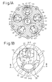
- Fig. 1A is a sectional view of a compressor
according to the first embodiment of the present
invention, taken along the line IA - IA in Fig. 5;
- Fig. 1B is an enlarged sectional view of a portion
of Fig. 1A;
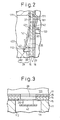
- Fig. 2 is a sectional view of the compressor, taken
along line II - II in Fig. 1B;
- Fig. 3 is a sectional view of the compressor, taken
along the line III - III in Fig. 1B;
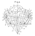
- Fig. 4 is an enlarged view of the suction port and
the suction valve;
- Fig. 5 is a sectional view of a portion of a
compressor according to the embodiment of the present
invention;
- Fig. 6A is an enlarged sectional view of a
compressor according to the second embodiment of the
present invention;
- Fig. 6B is an enlarged view of the suction port and
suction valve of Fig. 6A;
- Fig. 7 is an enlarged view of the suction port and
the suction valve according to the third embodiment;
- Fig. 8 is an enlarged view of the suction port and
the suction valve according to the fourth embodiment;
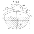
- Fig. 9 is an enlarged view of the suction port and
the suction valve according to the fifth embodiment;
- Fig. 10 is an enlarged view of the suction port and
the suction valve according to the sixth embodiment;
- Fig. 11 is an enlarged view of the suction port and
the suction valve according to the seventh embodiment;
and
- Fig. 12 is an enlarged view of the suction port and
the suction valve according to the eighth embodiment.
-
DESCRIPTION OF THE PREFERRED EMBODIMENTS
-
The first embodiment of the present invention
applied to a variable capacity type compressor will now
be explained with reference to Figs. 1A to 5.
-
Referring to Fig. 5, a front housing 12 is coupled
to the front end of a cylinder block 11, and a rear
housing 13 is fixed to the rear end of the cylinder block
11 via a partition plate 14, valve-forming plates 15 and
16 and a retainer-forming plate 17. A drive shaft 18 is
rotatably supported by the front housing 12 and the
cylinder block 11 which together form a control pressure
chamber 121. The drive shaft 18 protruding outward from
the control pressure chamber 121 receives a driving force
from an external driving source such as a car engine (not
shown) through a pulley (not shown) and a belt (not
shown).
-
A rotation support member 19 is anchored to the
drive shaft 18. The drive shaft 18 supports a swash
plate 20 in such a fashion that the swash plate 20 can
slide in an axial direction with respect to the drive
shaft 18 and can incline. The swash plate 20 can incline
with respect to the axis of the drive shaft 18 and can
rotate with the drive shaft 18, by the cooperation of a
pair of guide pins 21 fixed to the swash plate 20 and a
pair of guide holes 191 in the rotation support member
19. The inclination movement of the swash plate 20 is
guided by the slide guide relation between the guide hole
191 and the guide pin 21 as well as the slide support
operation of the drive shaft 18.
-
When the radial center portion of the swash plate 20
moves towards the rotation support member 19, the angle
of inclination of the swash plate 20 increases. When the
radial center portion of the swash plate 20 moves towards
the cylinder block 11, the angle of inclination of the
swash plate decreases. The minimum angle of inclination
of the swash plate 20 is defined by the abutment of a
circlip 22 fitted to the drive shaft 18 against the swash
plate 20. The maximum angle of inclination of the swash
plate 20 is defined by the abutment of the rotary support
member 19 against the swash plate 20. The position of
the swash plate 20 indicated by the solid line represents
the position of the minimum angle of inclination of the
swash plate 20. The position of the swash plate 20
indicated by the chain line represents the position of
the maximum angle of inclination of the swash plate 20.
-
As shown in Fig. 1A, a plurality of cylinder bores
111 (five, in this embodiment) are formed in the cylinder
block 11. The cylinder bores 111 are disposed
equidistantly about the drive shaft 18. Pistons 23 are
arranged in the cylinder bores 111, as shown in Fig. 5.
The rotating motion of the swash plate 20 is converted
into the reciprocating motion of the pistons 23 through
shoes 24, and the pistons 23 move back and forth in the
cylinder bores 111.
-
A suction chamber 131 and a discharge chamber 132
are defined in the rear housing 13. The discharge
chamber 132 surrounds the suction chamber 131 through a
partition wall 133. A supply passage 25 is arranged in
the rear wall of the rear housing 13.
-
As shown in Figs. 2 and 5, suction ports 26 are
formed in the partition plate 14, the valve-forming plate
16 and the retainer-forming plate 17 corresponding to the
cylinder bores 111. Discharge ports 27 are formed in the
partition plate 14 at positions corresponding to cylinder
bores 111. Suction valves 42 are formed in the valve-forming
plate 15, and discharge valves 161 are formed in
the valve-forming plate 16. Each of the suction valves
42 and the discharge valves 161 is integral with the
associated valve-forming plate, and is thus fixed at its
proximal end to the valve-forming plate while the
substantial part thereof is flexible. A window 421 is
formed in the proximal end portion of the suction valve
42 corresponding to the discharge port 27. The distal
end portion of the suction valve 42, that undergoes
flexural deformation, comes into, and out from, contact
with the contact surface 141 of the partition plate 14 on
the one side thereof and opens and closes the suction
port 26. The distal end portion of the discharge valve
161, that undergoes flexural deformation, comes into, and
out from, contact with the contact surface 142 of the
partition plate 14 on the other side thereof and opens
and closes the discharge port 27.
-
As shown in Figs. 1B and 2, a maximum opening
limiting recess 28 is formed in each cylinder bore 111.
The maximum opening limiting recess 28 has a side surface
281 and a bottom surface 282. The side surface 281 of
the maximum opening limiting recess 28 is a circular
circumferential surface. An engaging projection 422
having a semi-circular arcuate shape is formed at the
distal end of the suction valve 42. As shown in Fig. 2,
the engaging projection 422 can abut against the bottom
surface 282 of the maximum opening limiting recess 28,
and the maximum opening limiting recess 28 defines the
maximum opening of the suction valve 42. Fig. 3 shows
the maximum opening condition of the suction valve 42.
-
A refrigerant gas in the suction chamber 131 is
sucked through the suction port 26 into the cylinder bore
111, pushing the suction valve 42, during the returning
movement (movement from the right to the left in Fig. 5)
of the piston 23. The refrigerant gas in the cylinder
bore 111 is discharged through the discharge port 27 into
the discharge chamber 132, pushing the discharge valve
161 during the forward movement (movement from the left
to the right in Fig. 5) of the piston 23. As the
discharge valve 161 comes into contact with the retainer
171 on the retainer-forming plate 17, its opening is
restricted. The coolant discharged into the discharge
chamber 132 is fed to a condenser 30, an expansion valve
31 and an evaporator 32 on an external refrigerant
circuit 29 outside the compressor and returned to the
suction chamber 131 from the supply passage 25.
-
A solenoid-operated capacity control valve 34 is
arranged in a pressure feed passage 33 (shown in Fig. 1A)
that connects the discharge chamber 132 to a control
pressure chamber 121. The pressure feed passage 33
supplies the refrigerant gas in the discharge chamber 132
to the control pressure chamber 121. The solenoid-operated
capacity control valve 34 is activated and
inactivated by a controller (not shown), which controls
activation and deactivation of the solenoid-operated
capacity control valve 34 based on a detected compartment
temperature detected by a compartment temperature sensor
(not shown) detecting a compartment temperature of the
car and a target compartment temperature set by a
compartment temperature setter (not shown).
-
The refrigerant gas in the control pressure chamber
121 flows out to the suction chamber 131 through a
pressure release passage 35 (shown in Fig. 1A). When the
solenoid-operated capacity control valve 34 is in the
deactivated condition, the refrigerant gas in the
discharge chamber 132 is not delivered to the control
pressure chamber 121. Therefore, the pressure difference
between the control pressure in the control pressure
chamber 121 and the suction pressure on opposite sides of
the piston 23 becomes smaller, and the inclination angle
of the swash plate 20 shifts towards the maximum angle
side. When the solenoid-operated capacity control valve
34 is in the activated state, the refrigerant gas in the
discharge chamber 132 is delivered to the control
pressure chamber 121 through the pressure feed passage
33. Therefore, the pressure difference between the
control pressure in the control pressure chamber 121 and
the suction pressure on the opposite sides of the piston
23 becomes greater and the inclination angle of the swash
plate 20 shifts to the minimum angle side.
-
Fig. 4 shows the valve closing condition where the
suction valve 42 closes the suction port 26. The suction
port 26 is formed in the shape similar to a sector with
an apex portion of the sector removed. A contour line of
the suction port 26 positioned on the contact surface 141
of the partition plate 14 includes a proximal end line 36
positioned on the side of the proximal end of the suction
valve 42 (on the side of the window 421), a distal end
line 37 positioned on the side of the distal end of the
suction valve 42, a pair of right and left side lines 39
and 38, a first connection line 401 that interconnects
the proximal end line 36 and the side line 38, another
first connection line 402 that interconnects the proximal
end line 36 and the side line 39, a second connection
line 411 that interconnects the distal end line 37 and
the side line 38, and another second connection line 412
that interconnects the distal end line 37 and the side
line 39. The suction valve 42 has a symmetric shape with
respect to a reference line X extending in the
longitudinal direction of the suction valve 42, and the
suction port 26 has a symmetric shape with respect to the
reference line X. In other words, the left and right
portions of the suction valve 42 and the suction port 26
are symmetric.
-
The proximal end line 36 is a convex curve slightly
protruding from the distal end side of the suction valve
42 toward the proximal end side of the suction valve 42.
The distal end line 37 is a convex curve protruding from
the proximal end side of the suction valve 42 toward the
distal end side of the suction valve. The side lines 38
and 39 are approximately straight lines extending
substantially along the radial line r3 of the circle C
associated with the circumferential surface 112 of the
cylinder bore 111. The first connection line 401 is a
curve smoothly connected to the proximal end line 36 and
the side line 38 at positions L1 and L2, and another
first connection line 402 is a curve smoothly connected
to the proximal end line 36 and the side line 39 at
positions R1 and R2. The second connection line 411 is a
curve smoothly connected to the distal end line 37 and
the side line 38 at positions L3 and L4, and another
second connection line 412 is a curve smoothly connected
to the distal end line 37 and the side line 39 at
positions R3 and R4.
-
The bending angle 2 of the second connection lines
411 and 412 is greater than the bending angle 1 of the
first connection lines 401 and 402. The bending angle 1
represents an angle formed by normal lines m1 and m2 at
the positions L1 and L2 and an angle formed by normal
lines n1 and n2 at the positions R1 and R2. The bending
angle 2 represents an angle formed by normal lines m3
and m4 at positions L3 and L4 and an angle formed by
normal lines n3 and n4 at positions R3 and R4.
-
In this embodiment, each of the proximal end line
36, the distal end line 37, the first connection lines
401 and 402 and the second connection lines 411 and 412
comprises a circular arc. The radius of curvature of the
proximal end line 36 is greater than that of the distal
end line 37.
-
As shown in Figs. 1B and 4, the distal end portion
of the suction valve 42 comprises an outer contour line
extending along the distal end line 37, the second
connection lines 411 and 412 and the side lines 38 and 39
of the suction port 26. The outer contour line of the
distal end portion of the suction valve 42 comprises an
arcuate engaging line 43 defining the outer profile of
the engaging protrusion 422, a pair of right and left
distal end forming lines 44 and 45, a pair of right and
left side lines 46 and 47, a connection line 48
interconnecting the distal end forming line 44 and the
side line 46, and a connection line 49 interconnecting
the distal end line forming line 45 and the side line 47.
-
As shown in Fig. 4, the distal end forming lines 44
and 45 comprise an arcuate curve that is concentric with
the arcuate distal end line 37 of the suction port 26.
That is, the distance between the distal end line 37 of
the suction port 26 and the distal end forming lines 44
and 45 of the suction valve 42 with respect to the
direction of the arcuate radial lines r1 and r2 of the
arcuate distal end line 37 and the distal end forming
lines 44 and 45 is constant. The distance α between the
distal end line 37 of the suction port 26 and the distal
end forming lines 44 and 45 of the suction valve 42 with
respect to the direction of the radial line r3 of the
circle C of the cylinder bore 11 is not constant.
However, the change of the gap α is only slight and is
therefore substantially constant.
-
The side line 46 is a straight line parallel to the
side line 38 of the suction port 26, and the side line 47
is a straight line parallel to the side line 39 of the
suction port 26. The connection line 48 is an arcuate
curve concentric with the arcuate second connection line
411 of the suction port 26. The connection line 49 is an
arcuate curve concentric with the arcuate second
connection line 412 of the suction port 26. The
connection line 48 is a curve connected smoothly to the
distal end forming line 44 and the side line 46 at
positions Y1 and Y2. The connection line 49 is a curve
connected smoothly to the distal end forming line 45 and
the side line 47 at positions Z1 and Z2.
-
The radius of curvature of the arcuate distal end
line 37 is slightly smaller than the radius of the circle
C of the cylinder bore 111. The arc center 374 of the
distal end forming lines 44 and 45 of the suction valve
42 is slightly shifted from the center Co of the circle C
of the cylinder bore 111 towards the distal end of the
suction valve 42 along the reference line X. Therefore,
the gap β between the distal end forming lines 44, 45 of
the suction valve 42 and the circle C of the cylinder
bore 111 (the gap in the direction of the radial line r3
of the circle C of the cylinder bore 111) is not
constant, but the change of the gap β is slight and the
gap β is substantially constant.
-
The average of the gap β is greater than the gap γ
(shown in Fig. 2) between the suction valve 42 and the
distal end line 37 of the suction port 26 under the
maximum valve open state.
-
The refrigerant gas passing through the suction port
26 from the side of the suction chamber 131 towards the
side of the cylinder bore 111 flows between the contact
surface 141 of the partition plate 14 and the suction
valve 42 in the direction of the normal lines to the
outer contour line of the suction port 26 or the contact
surface 141 (the normal lines being represented by arrows
N1, N2, N3 and N4 in Fig. 1B). The refrigerant gas
flowing between the contact surface 141 and the suction
valve 42 in the direction of the normal lines N2, N3 and
N4 then flows from between the outer contour line of the
suction valve 42 and the contact surface 141 towards the
circumferential surface 112 of the cylinder bore 111.
The refrigerant gas flowing between the contact surface
141 and the suction valve 42 in the direction of the
normal line N1 then flows towards the window 421.
-
The first embodiment provides the following effects.
- (1-1) The refrigerant gas flowing towards the distal
end forming lines 44 and 45 in the direction of the
normal line N2 then flows in the returning direction of
the piston 23 from between the distal end forming lines
44 and 45 and the circumferential surface 112 of the
cylinder bore 111. The distance α between the distal
end forming lines 44 and 45 of the suction valve 42 and
the distal end line 37 of the suction port 26 is
substantially constant, and the distance β between the
distal end forming lines 44 and 45 and the
circumferential surface 112 of the cylinder bore 111 is
substantially constant. In other words, the distance (α
+ β) between the distal end 37 of the suction port 26 and
the circumferential surface 112 of the cylinder bore 111
in the direction of the radial line r2 is substantially
constant. Therefore, according to the construction in
which the distances α and β are substantially constant,
the refrigerant gas flowing towards the circumferential
surface 112 from between the suction valve 42 and the
distal end line 37 of the suction port 26 is apt to
impinge perpendicularly against the circumferential
surface 112.
The gas flowing from between the suction valve 42
and the distal end line 37 of the suction port 26 towards
the circumferential surface 112 of the cylinder bore 111
so as to perpendicularly impinge against the
circumferential surface 112 is apt to flow from between
the circumferential surface 112 of the cylinder bore 111
and the distal end forming lines 44 and 45 of the suction
valve 42 in the returning direction of the piston 23 (in
the direction from the right to the left in Fig. 5).
That is, the refrigerant gas flowing in the direction
perpendicular to the contour line of the suction port 26
close to the circumferential surface 112 of the cylinder
bore 111 (the distal end line 37) is not apt to flow in
the circumferential direction of the circumferential
surface 112 of the cylinder bore 111. The suction port
26 and the suction valve 42 providing such a flow of the
refrigerant gas improves easiness of the inflow of the
cooling gas into the cylinder bore 111 and also improves
compressor performance.
- (1-2) The radius r4 of the arcuate engaging line 43
is smaller than the arcuate radius r5 of the
circumferential side surface 281 of the maximum opening
limiting recess 28, so that the distance between the
engaging line 43 and the arc Ac of the side surface 281
at both ends thereof is great. Therefore, the
refrigerant gas flowing towards the engaging line 43 of
the engaging projection 422 in the direction of the
normal line N2 can flow more easily between the end
portions of the engaging line 43 and the end portions of
the arc Ac of the side surface 281 in the returning
direction of the piston 23. Such a flow of the
refrigerant gas contributes to an improvement in the ease
of the inflow of the refrigerant gas into the cylinder
bore 111.
- (1-3) As shown in Fig. 4, the suction port 26 is
offset from the center Co of the circle C of the
circumferential surface 112 of the cylinder bore 111.
Two radial lines r31 and r32 of the radial lines r3 of
the circle C of the circumferential surface 112 of the
cylinder bore 111 are tangential to the outer contour
line of the suction port 26, and form a predetermined
angle ω with respect to the center Co of the circle C.
The curve K in Fig. 4 is a part (arc) of a reference
circle concentric with the circle C, and ro is one of the
radial lines of the reference circle K. The reference
circle K crosses the connection lines 48 and 49, but most
part of the reference circle K exists between the contour
line of the suction port 26 and the outer contour line of
the suction valve 42 within the range of angle ω.
Moreover, the reference circle K does not cross the
distal end line 37 and the distal end forming lines 44
and 45. The arrangement in which most of the arc of the
reference circle K, which passes between the distal end
line 37 and the distal end forming lines 44 and 45 and is
concentric with the circuit C, falls between the contour
line of the suction port 26 and the outer contour line of
the suction valve 42, provides a substantially constant
gap α and a substantially constant gap β. The suction
port 25 and the suction valve 42 that have substantially
constant gaps α and β improve the ease of the inflow of
the refrigerant gas into the cylinder bore 111.
- (1-4) The average of the gap β between the
circumferential surface 112 of the cylinder bore 111 and
the distal end forming lines 44 and 45 of the suction
valve 42 is greater than the gap γ between the suction
valve 42 under the maximum valve opening condition and
the distal end line 37 of the suction port 26. The
portion of the gap γ between the suction valve 42 and the
distal end line 37 is located on the upstream side of the
portion of the gap β between the circumferential surface
112 of the cylinder bore 111 and the distal end forming
lines 44 and 45 of the suction valve 42, with respect to
the flow of the refrigerant gas. The construction in
which the average of the gap β of the cooling gas passage
portion located on the downstream side of the portion of
the gap γ is greater than the distance γ makes it easy
for the gas flowing perpendicularly impinge against the
circumferential surface 112 of the cylinder bore 111 to
flow in the returning direction of the piston 23.
- (1-5) The area S encompassed by the proximal end line
36, the distal end line 37, the side lines 38 and 39 and
the connection lines 401, 402, 411 and 412 is the flow
sectional area of the suction port 26. When the suction
port 26 is viewed in the reciprocating direction of the
piston 23, a middle line T shown in Fig. 4 passes through
the middle point Ho of the maximum length (represented by
H in Fig. 4) of the suction port 26 in the longitudinal
direction of the suction valve 42 (that is, in the
direction of the reference line X), extends transversely
with respect to the suction port 26, and perpendicularly
crosses the reference line X extending in the
longitudinal direction of the suction valve 42. When the
suction port 26 is viewed in the reciprocating direction
of the piston 23, the middle line T assumed in this way
divides the suction port 26 into first and second
sections 261 and 262. The area S2 of the second section
262 positioned on the distal end side of the suction
valve 42 is greater than the area S1 of the first section
261. The greater the area S2 of the second section 262
is than the area S1 of the first section 261, the greater
is the length of the contour line of the suction port 26
on the distal end side of the suction valve 42. In other
words, the more the center of gravity of the area of the
suction port 26 is shifted towards the distal end side of
the suction valve 42, the greater is the length of the
contour line of the suction port 26 on the distal end
side of the suction valve 42.
The opening gap γ of the suction valve 42 relative
to the partition plate 14 becomes greater towards the
distal end of the suction valve 42, as shown in Fig. 2.
Therefore, the greater the ratio of a portion of the
refrigerant gas passing through the suction port 26 on
the distal end side of the suction valve 42 is relative
to a portion of the refrigerant gas passing through the
suction port 26 on the proximal end side thereof, the
higher is the degree of improvement in the easy inflow of
the refrigerant gas into the cylinder bore 111 from the
suction chamber 131. The longer the length of the
contour line of the suction port 26 on the distal end
side of the suction valve 42 is, the greater is the
proportion of the flow of the refrigerant gas passing
through the suction port 26 on the distal end side
thereof relative to that on the proximal end side of the
suction valve 42. Therefore, the construction in which
the area S2 of the second section 262 is greater than the
area S1 of the first section 261 enables the gas to more
easily flow through the suction port 26 between the
suction valve 42 on the distal end side of the suction
valve 42 and the contact surface 141. As a result, the
ease of inflow of the refrigerant gas when the
refrigerant gas is sucked from the suction port 26 into
the cylinder bore 111 can be improved, and the
performance of the compressor can also be improved.
- (1-6) The width of the suction port 26 (represented
by W in Fig. 4) measured in the direction of the middle
line T becomes gradually greater in the longitudinal
direction of the suction valve 42 (in the direction of
the reference line X) from the proximal end side to the
distal end side of the suction valve 42, within the range
D shown in Fig. 4. The region Do of the suction port 26
(hatched with chain hatching lines in Fig. 4) within the
range D is a width increasing region where the width W
becomes gradually greater in the direction of the
reference line X from the proximal end side to the distal
end side of the suction valve 42. The length d of the
width increasing region Do in the direction of the
reference line occupies a major part of the maximum
length H of the suction port 26 in the direction of the
reference line X. The existence of such a width
increasing region Do is convenient for making the area S2
of the second section 262 greater than the area S1 of the
first section 261, and the length of the contour line of
the suction port 26 can be easily elongated as the width
increasing region Do is disposed. Therefore, the
existence of the width increasing region Do allows the
refrigerant gas passing through the suction port 26 to
more easily flow between the suction valve 42 and the
contact surface 141 on the distal end side of the suction
valve 42.
- (1-7) The maximum width of the suction port 26
(represented by Wo in Fig. 4) in the direction of the
middle line T exists in the second section 262. This
maximum width Wo is greater than the maximum length H of
the suction port 26 in the direction of the reference
line X. The construction in which the maximum length H
of the suction port 26 in the direction of the reference
line X is smaller than the maximum width Wo of the
suction port 26 in the direction of the middle line T is
more advantageous for elongating the contour line of the
suction port 26 on the distal end side of the suction
valve 42 than the case where H > Wo. The closer the
position of the maximum width Wo of the suction port 26
to the distal end of the suction valve 42, the more
advantages it becomes to elongate the contour line of the
suction port 26 on the distal end side of the suction
valve 42. In other words, the construction in which the
maximum length H of the suction port 26 in the direction
of the reference line X is smaller than the maximum width
Wo of the suction port 26 in the direction of the middle
line T and the maximum width Wo exists in the second
section 262 is convenient for elongating the length of
the contour line of the suction port 26 on the distal end
side of the suction valve 42.
- (1-8) The distal end line 37 is longer than the
proximal end line 36. The construction in which the
distal end line 37 is longer than the proximal end line
36 enables the refrigerant gas passing through the
suction port 26 to more easily flow towards the distal
end side of the suction valve 42.
- (1-9) The closer the distal end line 37 is to the
circle C of the circumferential surface 112 of the
cylinder bore 111, the greater is the opened gap γ
between the distal end line 37 and the suction valve 42
under the valve open condition. The greater the gap γ is
between the distal end line 37 and the suction valve 42,
the easier it becomes for the refrigerant gas to flow
into the cylinder bore 111. The distal end line 37 is an
arc protruding outward from the proximal end side to the
distal end side of the suction valve 42. The radius of
curvature of the distal end line 37 is slightly smaller
than the radius of the circle C of the circumferential
surface 112 of the cylinder bore 111. The construction
in which the distal end line 37 is the convex curve
approximate to the circle C of the circumferential
surface 112 of the cylinder bore 111 is advantageous for
bringing the distal end line 37 closer to the circle C of
the circumferential surface 112 of the cylinder bore 111.
- (1-10) The pressure in the cylinder bore 111 urges the
suction valve 42 against the periphery wall of the
suction port 26, in the condition where the refrigerant
gas in the cylinder bore 111 is discharged to the
discharge chamber 132, and the suction valve 42 closes
the suction port 26. In conjunction with the contour
line of the suction port 26, the smaller the length of
the contour line in the unit area, the more it becomes
difficult for the refrigerant gas to leak from the
cylinder bore 111 to the suction port 26 through the gap
between the contact surface 141 and the suction valve 42.
Supposing that a corner exists at a part of the contour
line of the suction port 26, however, the length of the
contour line in the unit area in the proximity of this
corner becomes large. Therefore, the construction in
which the corner exists at a part of the contour line of
the suction port 26 is likely to invite the backflow of
the refrigerant gas from the cylinder bore 111 to the
suction port 26. The backflow of the refrigerant gas
invites a drop in volumetric efficiency. The contour
line of the suction port 26 comprising the proximal end
line 36, the distal end line 37, the side lines 38 and
39, the first connection lines 401 and 402 and the second
connection lines 411 and 412 becomes an annular line
without any corner. The construction in which the
contour line of the suction port 26 is an annular line
without any corner is advantageous for preventing the
refrigerant gas from back-flowing from the cylinder bore
111 to the suction port 26.
- (1-11) The bending angle 2 of the second connection
lines 411 and 412 is greater than the bending angle 1 of
the first connection lines 401 and 402. Unless the
shapes of the proximal end line 36, the distal end line
37 and the side lines 38 and 39 change greatly, the
length of the distal end line 37 becomes progressively
greater as the bending angle 2 becomes progressively
greater than the bending angle 1. The construction in
which the bending angle 2 of the second connection lines
411 and 412 is greater than the bending angle 1 of the
first connection lines 401 and 402 is convenient as a
construction for increasing the length of the distal end
line 37.
- (1-12) The closer the contour line of the suction port
26 on the distal end side of the suction valve 42 is to
the circumferential surface 112 of the cylinder bore 111,
the easier it becomes for the refrigerant gas to flow
into the cylinder bore 111. Normally, the shapes of the
suction valve 42 and the suction port 26 are set to
symmetric shapes with respect to the reference line X,
respectively. Then, the contour line of the suction port
26 on the distal end side of the suction valve 42 becomes
symmetric with respect to the reference line X. When the
distal end line 37, which is symmetric with the reference
line X, is brought closer to the circumferential surface
112 of the cylinder bore 111 along the reference line X,
the distal end line 37 can be brought most closely to the
circumferential surface 112 of the cylinder bore 111 when
the reference line X is in conformity with the radial
line r3 of the circle C of the circumferential surface
112 of the cylinder bore 111. Therefore, the
construction in which the reference line X is allowed to
extend substantially along the radial line r3 of the
circle C of the circumferential surface 112 of the
cylinder bore 111 is advantageous for bringing the distal
end line 37 closer to the circle C of the circumferential
surface 112 of the cylinder bore 111.
- (1-13) In the piston compressor, self-induced
vibration may possibly occur during the shift of the
suction valve from the position in which it closes the
suction port to the maximum opening position, and this
self-induced vibration invites suction pulsation.
Suction pulsation causes the evaporator 32 in the
external coolant circuit 29 to vibrate and to generate
noise. In the variable capacity type compressor having
the pistons 23, the pistons 23 reciprocate with strokes
corresponding to the angle of inclination of the tiltable
swash plate 20 so that the capacity becomes small when
the angle of inclination of the swash plate 20 becomes
small. The average gas flow rate through the suction
ports is small under the low capacity condition, and the
suction valves may not abut against the bottom surfaces
282 of the maximum opening limiting recesses 28. In
consequence, self-induced vibration of the suction valve
is likely to occur in the variable capacity type
compressor.
-
-
In the construction in which the area S2 of the
second section 262 is greater than the area S1 of the
first section 261, the flow of the refrigerant gas
flowing from the suction chamber 131 into the cylinder
bore 111 is likely to more greatly concentrate on the
distal end side remote from the proximal end of the
suction valve 42, compared with the case of a suction
port such as the one described in Japanese Unexamined
Patent Publication (Kokai) No. 2000-54961, for example.
Therefore, the suction valve 42 may abut against the
bottom surface 282 of the maximum opening limiting recess
28 even under the low capacity condition, and self-induced
vibration of the suction valve 42 will be less
likely to occur.
-
Next, the second embodiment of the present invention
will be explained with reference to Figs. 6A and 6B, in
which like reference numerals are used to identify like
elements in the first embodiment.
-
The contour line of the suction port 26A comprises
the proximal end line 36, the distal end line 37, the
curved side lines 38A and 39A, the first connection lines
401A and 402A, and the second connection lines 411A and
412A. The radius of curvature of each of the first and
second connection lines 401A, 402A, 411A, and 412A is
greater than the radius of curvature of the first
connection lines 401 and 402 in the first embodiment.
The contour line of such a suction port 26A is an annular
line having no corner and no straight line. The outer
contour line of the suction valve 42A on the distal end
portion thereof comprises the engaging line 43, a pair of
right and left distal end forming lines 44 and 45, a pair
of right and left arcuate side lines 46A and 47A, the
arcuate connection line 48A interconnecting the distal
end forming line 44 and the side line 46, and the arcuate
connection line 49A interconnecting the distal end line
45 and the side line 47A. The radius of curvature of the
connection lines 48A and 49A is greater than the radius
of curvature of the connection lines 48 and 49 in the
first embodiment. The outer contour line of such a
suction valve 42A on the distal end portion thereof is a
line having no corner and no straight line.
-
The construction in which the contour line of the
suction port 26A is an annular line having no corner and
no straight line and the outer contour line of the
suction valve 42A on the distal end portion thereof is a
line having no corner and no straight line provides the
same effect as that of the first embodiment. The
construction in which the radius of curvature of the
connection lines 401A, 402A, 411A and 412A is greater
than the radius of curvature of the connection lines 401
and 402 in the first embodiment is much more advantageous
than the first embodiment for preventing the refrigerant
gas from back-flowing from the cylinder bore 111 to the
suction port 26A.
-
Fig. 7 shows the third embodiment and Fig. 8 shows
the fourth embodiment. Fig. 9 shows the fifth embodiment
and Fig. 10 shows the sixth embodiment. Like reference
numerals are used in these drawings to identify like
elements in the first and second embodiments.
-
The proximal end line 36B of the suction port 26B
shown in Fig. 7 is a concave curve recessed from the
proximal end side to the distal end side of the suction
valve 42A.
-
The distal end line 37C of the suction port 26C
shown in Fig. 8 is a part of an ellipse. The distal end
line 37C and a pair of side lines 38A and 39A are
smoothly connected at positions L5 and R5. Reference
numerals 44C and 45C denote distal end forming lines of
the suction valve 42C.
-
The proximal end line 36D of the suction port 26D
shown in Fig. 9 is a part of a circle and the distal end
line 37D is a part of an ellipse. The proximal end line
36D and the distal end line 37D are connected smoothly at
positions L6 and R6. Reference numerals 44D and 45D
denote the distal end forming lines of the suction valve
42D.
-
The suction port 26E shown in Fig. 10 represents the
shape formed by inverting the suction port described in
Japanese Unexamined Patent Publication (Kokai) No. 2000-54961
in the direction of the reference line X. The
proximal end line 36E of the suction port 26E is smoothly
connected to a pair of connection lines 411A and 412A.
Reference numerals 44E and 45E denote the distal end
forming lines of the suction valve 42E.
-
The distal end line 37F of the suction port 26F in
Fig. 11 comprises a first distal end line 371, a second
distal end line 372 and a connection line 373. The
connection line 373 is smoothly connected to the first
distal end line 371 and the second distal end line 372 at
positions L7 and R7. Reference numerals 44F and 45F
denote the distal end forming lines of the suction valve
42F.
-
The distal end line 37G of the suction port 26G
shown in Fig. 12 is a part of a circle, and the proximal
end line 36G is a part of an ellipse. The distal end
line 37G and the proximal end line 36G are smoothly
connected at positions L8 and R8. Reference numerals 44G
and 45G denote the distal end forming lines of the
suction valve 42G.
-
The distal end lines 37, 37C, 37D, 37F and 37G of
the suction ports 26B, 26C, 26D, 26E, 26F and 26G in the
embodiments shown in Figs. 7 to 12 and the distal end
forming lines 44, 45, 44C, 45C, 44D, 45D, 44E, 45E, 44F,
45F, 44G and 45G of the suction valves 42, 42A, 42C, 42D,
42E and 42F have the same relationship with the first
embodiment regarding the distances α, β and γ and the
reference circle K. The forming lines of the suction
ports 26B to 26F in the embodiments shown in Figs. 7 to
11 provide the same condition as the suction port 26 of
the first embodiment as to the size of the first and
second areas S1 and S2 of the first and second section
ranges 261 and 262, the length relationship of the
maximum length H and the width Wo and the relationship of
the length d of the width increasing region Do and the
maximum length H.
-
Incidentally, the present invention can also be
applied to suction ports having an asymmetric shape with
respect to the reference line. The shape of the engaging
line of the suction valve is not limited to the circular
arc but may have an arbitrary convex shape.
-
As described above in detail, in the present
invention, the outer contour line of the distal end
portion of the suction valve and the contour line of the
distal end portion of the suction port are disposed to
extend along the circle of the circumferential surface of
the cylinder bore, the gap between the distal end outer
contour line of the suction valve and the distal end
contour line of the suction port in the direction of the
radial line of the circle of the outer circumferential
surface of the cylinder bore is kept substantially
constant, and the gap between the distal end outer
contour line of the suction valve and the circumferential
surface of the cylinder bore in the direction of the
radial line is kept substantially constant. Therefore,
the present invention provides the excellent effect in
which facility of the inflow of the gas (lack of
resistance of inflow to the gas) can be improved when the
gas is sucked from the suction port to the cylinder bore.