Technical Field
This invention relates to an EGR cooler attached to
an EGR apparatus, which recirculates exhaust gas from an
engine to suppress generation of nitrogen oxides, so as to
cool the exhaust gas for recirculation.
Background Art
Known is an EGR apparatus which recirculates part of
exhaust gas from an engine in a vehicle or the like to the
engine to suppress generation of nitrogen oxides. In such
an EGR apparatus, cooling the exhaust gas to be
recirculated to the engine will drop the temperature of
and reduce the volume of the exhaust gas to lower the
combustion temperature in the engine without substantial
decrease of output thereof, thereby effectively
suppressing generation of nitrogen oxides. To this end,
some EGR apparatuses are equipped with, midway of exhaust
gas recirculation lines to the engines, EGR coolers for
cooling the exhaust gas.
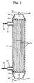
Fig. 1 is a sectional view showing an example of the
above-described EGR cooler wherein reference numeral 1
denotes a cylindrical shell with axial opposite ends to
which plates 2 are respectively fixed to close the ends of
the shell 1. Penetratingly fixed to the respective plates
2 are opposite ends of a number of tubes 3 which extend
axially within the shell 1.
A cooling water inlet 4 is attached from outside to
the shell 1 near one end thereof and a cooling water
outlet 5 is attached from outside to the shell 1 near the
other end thereof so that cooling water 9 is supplied via
the cooling water inlet 4 into the shell 1, flows outside
of the tubes 3 and is discharged via the cooling water
outlet 5 out of the shell 1.
The respective plates 2 have, on their sides away
from the shell 1, bowl-shaped hoods 6 fixed to the plates
2 so as to enclose end faces of the plates 2. The one and
the other hoods 6 provide central exhaust gas inlet and
outlet 7 and 8, respectively, so that the exhaust gas 10
from the engine enters via the exhaust gas inlet 7 into
the one hood 6, is cooled, during passage through the
tubes 3, by heat exchange with the cooling water 9 flowing
outside of the tubes 3 and is discharged to the other hood
6 to be recirculated to the engine via the exhaust gas
outlet 8.
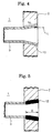
In such conventional EGR cooler, however, the end of
the tube 3 penetrates into and is fixed to the plate 2 via
a brazed portion 11 as shown in Fig. 2 in an enlarged
scale. Especially on an outlet side of the exhaust gas 10
as shown, cooling the exhaust gas 10 in the tube 3 will
generate condensate containing a vitriolic component which
may flow out via the outlet of the tube 3 and corrode the
brazing metal (generally nickel brazing metal)
constituting the brazed portion 11. If the cooling water
9 should leak therethrough, it may be guided to the engine,
causing a trouble.
Contemplated nowadays is welding the end of the tube
3 to the plate 2 by laser radiation L as shown in Fig. 3.
Use of this kind of laser radiation will advantageously
bring about laser weld 12 highly resistive against
corrosion by the condensate; on the other hand, the weld
penetration by the laser radiation L does not reach deep
and sufficient weld depth D is hard to obtain, resulting
in the laser weld 12 with low bonding strength. If the
tube 3 should have undergone excessive thermal expansion,
the laser weld 12 may be damaged to cause leakage of the
cooling water 9.
More specifically, upon laser-welding the end of the
tube 3 to the plate 2, generally effected is laser
radiation L on the side of the plate 2 away from the shell
1 and in parallel with the axis of the tube 3, and welded
is a boundary between the plate 2 and the end face of the
tube 3 with weld depth D of the order of a wall thickness
of the tube 3. As a result, only obtainable is the laser
weld 12 having strength lower than that of the tube 3
itself.
In an actual operation, laser radiation L is effected
from directly above, with the tube 3 being stood upright.
Therefore, to merely increase the laser intensity for the
purpose of increasing the weld depth will
disadvantageously result in an increased possibility that
the molten portion may flow into the tube 3 to narrow the
flow channel. Thus, to increase the laser intensity is
inherently limitative.
Furthermore, as described above, with the laser weld
12 having the shallow weld depth D, the tube 3 is welded
to a through-hole 13 of the plate 2 over only a small area
on the side away from the shell 1. Therefore, minute
crevice may be formed over a major part of the boundary
between the through-hole 13 and the tube 3. In this
crevice, cavitation may occur due to variation of
hydraulic pressure derived from minute vibrations of the
tube 3, resulting in generation of crevice corrosion in a
deepest portion of the crevice (a portion abutting on the
laser weld 12). As a result, the end of the tube 3 may be
damaged to cause leakage of the cooling water 9.
The present invention was made in view of the above
facts and has its object to prevent the cooling water from
leaking out to the flow channels of the exhaust gas,
thereby preventing engine trouble from occurring.
Summary of The Invention
An EGR cooler according to claim 1 of the invention
comprises a cylindrical shell, plates fixed to axial
opposite ends of said shell so as to close the ends of the
shell, hoods fixed to sides of the plates away from said
shell so as to enclose end faces of the plates, tubes
extending axially within the shell and having opposite
ends penetratingly fixed to the respective plates, cooling
water being supplied into and discharged from said shell,
exhaust gas being passed through said tubes from one of
the hoods to the other hood for thermal exchange of said
exhaust gas with said cooling water, and is characterized
in that an end of the tube penetrating the plate is formed
as a tapered portion with diameter gradually increased
toward the side away from the shell, the tapered portion
being wholly welded to the plate by laser radiation from
the side away from the shell.
In this manner, when the end of the tube is formed as
the tapered portion with diameter gradually increased
toward the side away from the shell, the inner periphery
of the tapered portion has a shape divergent to the side
away from the shell to have a bevel in the form of mortar,
so that laser radiation from the side away from the shell
can be readily carried out throughout the inner periphery
of the tapered portion.
Then, a resulting laser weld has a high bonding
strength, the weld depth being increased to an extent
corresponding to the thickness of the plate. Moreover,
formation of minute crevice between the tube and the
through-hole of the plate is avoided so that no crevice
corrosion occurs.
An EGR cooler according to claim 2 of the invention
comprises a cylindrical shell, plates fixed to axial
opposite ends of said shell so as to close the ends of the
shell, hoods fixed to sides of the plates away from said
shell so as to enclose end faces of the plates, tubes
extending axially within the shell and having opposite
ends penetratingly fixed to the respective plates, cooling
water being supplied into and discharged from said shell,
exhaust gas being passed through said tubes from one of
the hoods to the other hood for thermal exchange of said
exhaust gas with said cooling water, and is characterized
in that an end of the tube penetrates into a through-hole
of the plate which is formed with a notch on the side
toward the shell, and is welded to the plate by laser
radiation from the side away from the shell such that a
laser weld reaches the notch.
In this manner, with the through-hole of the plate
being formed with the notch on the side toward the shell,
an unwelded portion is left as the notch widely opened to
the shell when the end of the tube is welded to the plate
by means of laser radiation from the side away from the
shell such that the laser weld reaches the notch. As a
result, no minute crevice is formed between the tube and
the through-hole of the plate and no crevice corrosion
occurs. It is therefore possible to have a structure
which, under the condition that no crevice corrosion
occurs, has the laser intensity increased to such a degree
that no portion melted by the laser radiation will flow
into the tube to narrow the channel, and the weld depth
increased as much as possible to increase the bonding
strength of the laser weld as high as possible.
An EGR cooler according to claim 3 of the invention
comprises a cylindrical shell, plates fixed to axial
opposite ends of said shell so as to close the ends of the
shell, hoods fixed to sides of the plates away from said
shell so as to enclose end faces of the plates, tubes
extending axially within the shell and having opposite
ends penetratingly fixed to the respective plates, cooling
water being supplied into and discharged from said shell,
exhaust gas being passed through said tubes from one of
the hoods to the other hood for thermal exchange of said
exhaust gas with said cooling water, and is characterized
in that the tubes penetrate into and are fixed to the
plate via brazed portions such that an end of the tube
extends out from the plate by a predetermined length and
the extending end of the tube penetrates into and is fixed
to a sub plate by laser weld, whereby said sub plate
covers said brazed portions.
Thus, such covering of the plate with the sub plate
will cause any condensate containing a vitriolic component,
which may be generated by cooling the exhaust gas in the
tube and may flow out via the outlet of the tube, to be
isolated by the sub plate to which the tubes penetratingly
fixed via the laser welds having high resistance against
corrosion such that no condensate contacts the brazed
portions of the plate. As a result, corrosion of the
brazing filler metal constituting the brazed portions due
to the condensate is positively avoided while the bonding
strength of the tubes to the plate is kept high by the
brazed portions. Even if water should leak due to any
crack created in the brazed portions, the cooling water is
dammed by the sub plate to stay between the sub plate and
the plate.
An EGR cooler according to claim 4 of the invention
comprises a shell in the form of a cylindrical container,
tubes extending axially within the shell and having
opposite ends penetratingly fixed to axial opposite ends
of said shell, cooling water being supplied into and
discharged from said shell, exhaust gas being passed
through said tubes for thermal exchange of said exhaust
gas with said cooling water, and is characterized in that
the tubes have increased diameter and thickness so as to
increase cross sectional areas and strength of flow
channels, a gas flange being fitted over tips of the
respective tubes extruded out of the shell.
This allows the number of tubes to be reduced to a
required minimum and line for recirculation of exhaust gas
may be properly branched and directly connected to the gas
flange at the tips of the respective tubes extruded out of
the shell. Therefore, even if condensate containing a
vitriolic component is generated due to cooling of the
exhaust gas in the tubes, avoided is its adverse effect
such as corrosion on the penetrating fixed portions of the
tubes to the shell. If a crack should be generated on the
penetrating fixed portions of the tubes to the shell to
cause water leakage, the leaked, cooling water leaks out
only outside of the shell and is prevented from intruding
into the flow channels of the exhaust gas.
Brief Description of Drawings
Fig. 1 is a sectional view showing a conventional EGR
cooler;
Fig. 2 is an enlarged sectional view showing details
of a penetrating, fixed portion between a tube and a plate
in Fig. 1;
Fig. 3 is an enlarged sectional view showing another
example of the penetrating, fixed portion between the tube
and the plate;
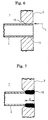
Fig. 4 is an enlarged sectional view showing an
embodiment of the invention as set forth in claim 1;
Fig. 5 is an enlarged sectional view showing the tube
laser-welded to the plate in Fig. 4;
Fig. 6 is an enlarged sectional view showing an
embodiment of the invention as set forth in claim 2;
Fig. 7 is an enlarged sectional view showing the tube
laser-welded to the plate in Fig. 6;
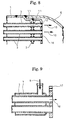
Fig. 8 is an enlarged sectional view showing an
embodiment of the invention as set forth in claim 3; and
Fig. 9 is an enlarged sectional view showing an
embodiment of the invention as set forth in claim 4.
Best Mode for Carrying Out the Invention
Now, embodiments of the invention will be described
with reference to the drawings.
Figs. 4 and 5 show an embodiment of the invention as
set forth in claim 1 in which the same parts as those in
Figs. 1 to 3 are denoted by the same reference numerals.
In this embodiment, with regard to an EGR cooler
constructed substantially in the same manner as that
described above with reference to Fig. 1, an end of a tube
3 penetrating a plate 2 is formed as a tapered portion 14
with diameter gradually increased toward the side away
from a shell 1; the tapered portion 14 is wholly welded to
the plate 2 by laser radiation L from the side away from
the shell 1.
In this manner, when the end of the tube 3 is formed
as the tapered portion 14 with diameter gradually
increased toward the side away from the shell 1, the inner
periphery of the tapered portion 14 has a shape divergent
to the side away from the shell 1 to have a bevel in the
form of mortar, so that laser radiation L from the side
away from the shell 1 can be readily carried out
throughout the inner periphery of the tapered portion.
Then, a resulting laser weld 12 has a high bonding
strength, the weld depth D being increased to an extent
corresponding to the thickness of the plate 2. Moreover,
formation of minute crevice between the tube 3 and a
through-hole 13 of the plate 2 is avoided so that no
crevice corrosion occurs.
Therefore, according to the above embodiment, the
laser weld 12 highly resistant against corrosion allows
the tube 3 to be penetratingly fixed to the plate 2 with a
high bonding strength, the weld depth D being increased in
comparison with the conventional cases. Moreover,
formation of minute crevice between the tube 3 and the
through-hole 13 of the plate 2 is avoided to prevent
crevice corrosion from occurring. As a result, the
cooling water 9 can be positively prevented from leaking
out to the flow channel of the exhaust gas 10, which
eliminates any possibility of the cooling water 9 being
guided to the engine, thereby preventing engine trouble
from occurring.
Figs. 6 and 7 show an embodiment of the invention as
set forth in claim 2. In this embodiment, an end of a
tube 3 penetrates into a through-hole 13 of a plate 2
which is formed with a notch 15 on the side toward the
shell 1, and is welded to the plate 2 by laser radiation L
from the side away from the shell 1 such that a laser weld
12 reaches the notch 15.
In this manner, with the through-hole 13 of the plate
2 being formed with the notch 15 on the side toward the
shell 1, an unwelded portion is left as the notch 15
widely opened to the shell 1 when the end of the tube 3 is
welded to the plate 2 by laser radiation L from the side
away from the shell 1 such that the laser weld 12 reaches
the notch 15. As a result, no minute crevice is formed
between the tube 3 and the through-hole 13 of the plate 2
and no crevice corrosion occurs. It is therefore possible
to have a structure which, under the condition that no
crevice corrosion occurs, has the laser intensity
increased to such a degree that no portion melted by the
laser radiation L will flow into the tube 3 to narrow the
channel, and the weld depth D increased as much as
possible to increase the bonding strength of the laser
weld 12 as high as possible.
Accordingly, also in this embodiment, formation of
minute crevice between the tube 3 and the through-hole 13
of the plate 2 can be avoided to prevent crevice corrosion
from occurring. As a result, the cooling water 9 can be
positively prevented from leaking out to the flow channel
of the exhaust gas 10, which eliminates the possibility of
the cooling water 9 being guided to the engine, thereby
preventing engine trouble from occurring.
Fig. 8 shows an embodiment of the invention as set
forth in claim 3. In this embodiment, tubes 3 penetrate
into and are fixed to a plate 2 via brazed portions 11
such that an end of the tube 3 extends out from the plate
2 by a predetermined length and the extending end of the
tube 3 penetrates into and is fixed to a sub plate 16 by
laser weld 12. Thus, the sub plate 16 covers the brazed
portions 11.
Especially in this embodiment, an outer periphery of
the plate 2 is bent toward the axial direction of the tube
3 with a stepped portion being intervened, and the shell 1
and the bonnet 6 are butt-welded with the outer periphery
of the plate 2 being therebetween.
Thus, such covering of the plate 2 with the sub plate
16 will cause any condensate containing a vitriolic
component, which may be generated by cooling the exhaust
gas 10 in the tube 3 and may flow out via the outlet of
the tube 3, to be isolated by the sub plate 16 to which
the tubes 3 penetratingly fixed via the laser welds 12
having high resistance against corrosion such that no
condensate contacts the brazed portions 11 of the plate 2.
As a result, corrosion of the brazing filler metal
constituting the brazed portions 11 due to the condensate
is positively avoided while the bonding strength of the
tubes 3 to the plate 2 is kept high by the brazed portions
11. Even if water should leak due to any crack created in
the brazed portions 11, the cooling water 9 is dammed by
the sub plate 16 to stay between the sub plate 16 and the
plate 2.
Therefore, according to the above embodiment, the
brazed portion 11 can be protected by the sub plate 16
against the condensate of the exhaust gas 10 while kept
high is the bonding strength of the tubes 3 to the plate 2
by the brazed portions 11. As a result, corrosion of the
brazed portions 11 can be prevented from occurring. Even
if a crack may occur in the brazed portion 11 due to a
factor other than the condensate of the exhaust gas 10,
resulting in water leakage, the cooling water 9 can be
dammed by the sub plate 16 to be accumulated between the
sub plate 16 and the plate 2. As a result, the cooling
water 9 may not be guided to the engine, and engine
trouble can be prevented from occurring.
Fig. 9 shows an embodiment of the invention as set
forth in claim 4. Used in this embodiment is a structure
with a shell 1 in the form of a cylindrical container;
opposite ends of tubes 3 axially extend in a shell 1 and
are penetratingly fixed to opposite axial ends of the
shell 1, respectively; the tubes 3 are increased in
diameter and thickness in comparison with the conventional
cases to increase flow sectional areas and strengths of
flow channels, which allows the number of tubes 3 to be
reduced to a required minimum (for example, three or so).
A gas flange 17 is fitted over tips of the respective
tubes 3 extruded out of the shell 1.
More specifically, in the conventional EGR coolers,
the tubes 3 are decreased in diameter and thickness for
effective cooling of the recirculated exhaust gas 10,
which causes a cross sectional area per tube 3 to be
decreased, resulting in necessity of using a great number
of tubes 3 and of using a structure in which the tubes are
supported by the plates 2 for passing of all the tubes 3
into the hoods 6. By contrast, according to this
embodiment, the tubes 3 are increased in diameter and
thickness in comparison with the conventional cases to
increase the cross sectional areas and the strengths of
the flow channels, which allows the number of tubes 3 to
be reduced to a required minimum.
However, of course, the shell 1 and tube 3 must be
properly increased in length so as to maintain the cooling
efficiency as before.
As described above, when the number of tubes 3 is
reduced to a required minimum and the ends of the
respective tubes 3 are penetratingly fixed to the axial
opposite ends of the shell 1, line for recirculation of
exhaust gas 10 may be properly branched and directly
connected to the gas flange 17 at the tips of the
respective tubes 3 extruded out of the shell 1. Therefore,
even if condensate containing a vitriolic component is
generated due to cooling of the exhaust gas 10 in the
tubes 3, avoided is its adverse effect such as corrosion
on the penetrating fixed portions of the tubes 3 to the
shell 1. If a crack should be generated on the
penetrating fixed portions of the tubes 3 to the shell 1
to cause water leakage, the leaked, cooling water 9 leaks
out only outside of the shell 1 and is prevented from
intruding into the flow channels of the exhaust gas 10.
Therefore, according to the above embodiment, it can
be positively avoided that the condensate of the exhaust
gas 10 has an adverse effect such as corrosion on the
penetrating, fixed portions of the tubes 3 to the shell 1.
Moreover, even if a crack should occur in the penetrating,
fixed portions due to a factor other than the condensate
of the exhaust gas 10 to cause water leakage, the leaked
cooling water 9 can be positively prevented from intruding
into the flow channels of the exhaust gas 10. As a result,
the cooling water 9 may not be guided to the engine and
engine trouble is prevented from occurring.
It is to be understood that the EGR cooler of the
invention is not limited to the above embodiments and that
various changes and modifications may be made without
departing from the scope of the invention. For example,
the outlet side of the exhaust gas is shown in the
drawings; however, similar construction may be applicable
on the inlet side of the exhaust gas.
Industrial Applicability
As described above, the EGR cooler according to the
invention is suitable for use in an EGR apparatus for
recirculating exhaust gas from the engine to suppress
generation of nitrogen oxides.