EP1154132A2 - Apparatus and method for controlling duty ratio for cooling fan associated motor of vehicle - Google Patents
Apparatus and method for controlling duty ratio for cooling fan associated motor of vehicle Download PDFInfo
- Publication number
- EP1154132A2 EP1154132A2 EP01303676A EP01303676A EP1154132A2 EP 1154132 A2 EP1154132 A2 EP 1154132A2 EP 01303676 A EP01303676 A EP 01303676A EP 01303676 A EP01303676 A EP 01303676A EP 1154132 A2 EP1154132 A2 EP 1154132A2
- Authority
- EP
- European Patent Office
- Prior art keywords
- duty ratio
- torque
- generator
- coolant temperature
- value
- Prior art date
- Legal status (The legal status is an assumption and is not a legal conclusion. Google has not performed a legal analysis and makes no representation as to the accuracy of the status listed.)
- Withdrawn
Links
Images
Classifications
-
- F—MECHANICAL ENGINEERING; LIGHTING; HEATING; WEAPONS; BLASTING
- F01—MACHINES OR ENGINES IN GENERAL; ENGINE PLANTS IN GENERAL; STEAM ENGINES
- F01P—COOLING OF MACHINES OR ENGINES IN GENERAL; COOLING OF INTERNAL-COMBUSTION ENGINES
- F01P7/00—Controlling of coolant flow
- F01P7/02—Controlling of coolant flow the coolant being cooling-air
- F01P7/04—Controlling of coolant flow the coolant being cooling-air by varying pump speed, e.g. by changing pump-drive gear ratio
- F01P7/048—Controlling of coolant flow the coolant being cooling-air by varying pump speed, e.g. by changing pump-drive gear ratio using electrical drives
-
- B—PERFORMING OPERATIONS; TRANSPORTING
- B60—VEHICLES IN GENERAL
- B60H—ARRANGEMENTS OF HEATING, COOLING, VENTILATING OR OTHER AIR-TREATING DEVICES SPECIALLY ADAPTED FOR PASSENGER OR GOODS SPACES OF VEHICLES
- B60H1/00—Heating, cooling or ventilating devices
- B60H1/32—Cooling devices
- B60H1/3204—Cooling devices using compression
- B60H1/3205—Control means therefor
-
- B—PERFORMING OPERATIONS; TRANSPORTING
- B60—VEHICLES IN GENERAL
- B60H—ARRANGEMENTS OF HEATING, COOLING, VENTILATING OR OTHER AIR-TREATING DEVICES SPECIALLY ADAPTED FOR PASSENGER OR GOODS SPACES OF VEHICLES
- B60H1/00—Heating, cooling or ventilating devices
- B60H1/32—Cooling devices
- B60H1/3204—Cooling devices using compression
- B60H1/3205—Control means therefor
- B60H1/3208—Vehicle drive related control of the compressor drive means, e.g. for fuel saving purposes
-
- B—PERFORMING OPERATIONS; TRANSPORTING
- B60—VEHICLES IN GENERAL
- B60H—ARRANGEMENTS OF HEATING, COOLING, VENTILATING OR OTHER AIR-TREATING DEVICES SPECIALLY ADAPTED FOR PASSENGER OR GOODS SPACES OF VEHICLES
- B60H1/00—Heating, cooling or ventilating devices
- B60H1/32—Cooling devices
- B60H2001/3236—Cooling devices information from a variable is obtained
- B60H2001/3248—Cooling devices information from a variable is obtained related to pressure
-
- B—PERFORMING OPERATIONS; TRANSPORTING
- B60—VEHICLES IN GENERAL
- B60H—ARRANGEMENTS OF HEATING, COOLING, VENTILATING OR OTHER AIR-TREATING DEVICES SPECIALLY ADAPTED FOR PASSENGER OR GOODS SPACES OF VEHICLES
- B60H1/00—Heating, cooling or ventilating devices
- B60H1/32—Cooling devices
- B60H2001/3236—Cooling devices information from a variable is obtained
- B60H2001/3255—Cooling devices information from a variable is obtained related to temperature
-
- B—PERFORMING OPERATIONS; TRANSPORTING
- B60—VEHICLES IN GENERAL
- B60H—ARRANGEMENTS OF HEATING, COOLING, VENTILATING OR OTHER AIR-TREATING DEVICES SPECIALLY ADAPTED FOR PASSENGER OR GOODS SPACES OF VEHICLES
- B60H1/00—Heating, cooling or ventilating devices
- B60H1/32—Cooling devices
- B60H2001/3236—Cooling devices information from a variable is obtained
- B60H2001/3266—Cooling devices information from a variable is obtained related to the operation of the vehicle
-
- B—PERFORMING OPERATIONS; TRANSPORTING
- B60—VEHICLES IN GENERAL
- B60H—ARRANGEMENTS OF HEATING, COOLING, VENTILATING OR OTHER AIR-TREATING DEVICES SPECIALLY ADAPTED FOR PASSENGER OR GOODS SPACES OF VEHICLES
- B60H1/00—Heating, cooling or ventilating devices
- B60H1/32—Cooling devices
- B60H2001/3269—Cooling devices output of a control signal
- B60H2001/3276—Cooling devices output of a control signal related to a condensing unit
- B60H2001/3277—Cooling devices output of a control signal related to a condensing unit to control the air flow
-
- F—MECHANICAL ENGINEERING; LIGHTING; HEATING; WEAPONS; BLASTING
- F01—MACHINES OR ENGINES IN GENERAL; ENGINE PLANTS IN GENERAL; STEAM ENGINES
- F01P—COOLING OF MACHINES OR ENGINES IN GENERAL; COOLING OF INTERNAL-COMBUSTION ENGINES
- F01P5/00—Pumping cooling-air or liquid coolants
- F01P5/02—Pumping cooling-air; Arrangements of cooling-air pumps, e.g. fans or blowers
- F01P2005/025—Pumping cooling-air; Arrangements of cooling-air pumps, e.g. fans or blowers using two or more air pumps
-
- F—MECHANICAL ENGINEERING; LIGHTING; HEATING; WEAPONS; BLASTING
- F01—MACHINES OR ENGINES IN GENERAL; ENGINE PLANTS IN GENERAL; STEAM ENGINES
- F01P—COOLING OF MACHINES OR ENGINES IN GENERAL; COOLING OF INTERNAL-COMBUSTION ENGINES
- F01P5/00—Pumping cooling-air or liquid coolants
- F01P5/02—Pumping cooling-air; Arrangements of cooling-air pumps, e.g. fans or blowers
- F01P5/04—Pump-driving arrangements
- F01P2005/046—Pump-driving arrangements with electrical pump drive
-
- F—MECHANICAL ENGINEERING; LIGHTING; HEATING; WEAPONS; BLASTING
- F01—MACHINES OR ENGINES IN GENERAL; ENGINE PLANTS IN GENERAL; STEAM ENGINES
- F01P—COOLING OF MACHINES OR ENGINES IN GENERAL; COOLING OF INTERNAL-COMBUSTION ENGINES
- F01P2023/00—Signal processing; Details thereof
-
- F—MECHANICAL ENGINEERING; LIGHTING; HEATING; WEAPONS; BLASTING
- F01—MACHINES OR ENGINES IN GENERAL; ENGINE PLANTS IN GENERAL; STEAM ENGINES
- F01P—COOLING OF MACHINES OR ENGINES IN GENERAL; COOLING OF INTERNAL-COMBUSTION ENGINES
- F01P2025/00—Measuring
- F01P2025/04—Pressure
-
- F—MECHANICAL ENGINEERING; LIGHTING; HEATING; WEAPONS; BLASTING
- F01—MACHINES OR ENGINES IN GENERAL; ENGINE PLANTS IN GENERAL; STEAM ENGINES
- F01P—COOLING OF MACHINES OR ENGINES IN GENERAL; COOLING OF INTERNAL-COMBUSTION ENGINES
- F01P2025/00—Measuring
- F01P2025/08—Temperature
-
- F—MECHANICAL ENGINEERING; LIGHTING; HEATING; WEAPONS; BLASTING
- F01—MACHINES OR ENGINES IN GENERAL; ENGINE PLANTS IN GENERAL; STEAM ENGINES
- F01P—COOLING OF MACHINES OR ENGINES IN GENERAL; COOLING OF INTERNAL-COMBUSTION ENGINES
- F01P2025/00—Measuring
- F01P2025/60—Operating parameters
- F01P2025/64—Number of revolutions
-
- F—MECHANICAL ENGINEERING; LIGHTING; HEATING; WEAPONS; BLASTING
- F01—MACHINES OR ENGINES IN GENERAL; ENGINE PLANTS IN GENERAL; STEAM ENGINES
- F01P—COOLING OF MACHINES OR ENGINES IN GENERAL; COOLING OF INTERNAL-COMBUSTION ENGINES
- F01P2060/00—Cooling circuits using auxiliaries
- F01P2060/14—Condenser
Definitions
- the present invention relates generally to controlling apparatus and method for controlling a duty ratio for a cooling fan associated motor (hereinafter, also simply referred to as a fan motor) of an automotive vehicle, particularly, relates to the controlling apparatus and method for controlling the duty ratio of the cooling fan associated motor of an engine cooling radiator and a condenser of a vehicular air conditioner.
- a cooling fan associated motor hereinafter, also simply referred to as a fan motor
- a Japanese Patent Application First Publication No. Heisei 11-229876 published on August 24, 1999 exemplifies a previously proposed automotive vehicle cooling system having a cooling fan associated motor to cool a radiator and a condenser of a vehicular air conditioner through the cooling fans to cool a radiator of an engine and a condenser of the air conditioner.
- Pulse Width Modulation is carried out by detecting a refrigerant pressure of the air conditioner and a coolant temperature and calculating a duty ratio of the cooling fan in accordance with the coolant temperature and the refrigerant pressure.
- the cooling fan associated motor is constituted by two or more cooling fans and associated motors, a beat tone is often developed in accordance with individual product difference or fan profile difference when two or more motors are controlled at the same frequencies.
- an object of the present invention to provide controlling apparatus and method for controlling a duty ratio of each cooling fan associated motor of an automotive vehicle.
- a method for controlling a cooling fan associated motor at a pulse duty ratio the cooling fan being revolved by the cooling fan associated motor to cool a radiator of a vehicular engine coolant and a condenser of a refrigerant of a vehicular air conditioner, the method comprising: controlling the duty ratio for the cooling fan associated motor in such a manner that a sum of a torque required for a generator to drive the cooling fan associated motor and a torque required to drive a compressor of the air conditioner is minimized while satisfying a control demand for a coolant temperature and a refrigerant pressure.
- an apparatus for controlling a cooling fan associated motor at a pulse duty ratio the cooling fan being revolved by the cooling fan associated motor to cool a radiator of a vehicular engine coolant and a condenser of a refrigerant of a vehicular air conditioner
- the apparatus comprising: a controller to control the duty ratio for the cooling fan associated motor in such a manner that a sum of a torque required for a generator to drive the cooling fan associated motor and a torque required to drive a compressor of the air conditioner is minimized while satisfying a control demand for a coolant temperature and a refrigerant pressure; and a driver to drive the cooling associated motor at the duty ratio.
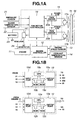
- Fig. 1A is a schematic circuit block diagram of a vehicular cooling system to which a preferred embodiment of a cooling fan associated motor controlling apparatus is applicable.
- Fig. 1B is a schematic circuit block diagram of a fan motor controller and an engine controller shown in Fig. 1A.
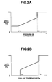
- Fig. 2A is a characteristic graph of a map representing a relationship between a duty ratio for the cooling fan associated motor and a refrigerant pressure.
- Fig. 2B is a characteristic graph of a map representing a relationship between the duty ratio and a coolant temperature.
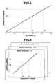
- Fig. 3 is a characteristic graph of a map representing the duty ratio and a generator current.
- Fig. 4 is a characteristic graph of maps representing relationships between the generator's torque and generator current with engine speed as a parameter.
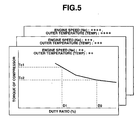
- Fig. 5 is a characteristic graph of maps representing a torque of a compressor and duty ratio with the engine speed and outer temperature as parameters.
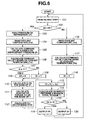
- Fig. 6 is an operational flowchart for explaining an operation of the cooling fan motor controller shown in Fig. 1A.
- Fig. 1A shows a schematic circuit block diagram of a vehicular cooling system to which a cooling fan duty ratio controlling apparatus in a preferred embodiment according to the present invention is applicable.
- An engine speed sensor 13 and a coolant temperature sensor 14 are connected to an engine controller 12 to control an engine operation of an engine 11.
- the engine speed sensor 13 detects an engine speed and the coolant temperature 14 to detect an engine coolant temperature.
- An engine coolant of the engine 11 is cooled with a radiator 15 which is arranged within an engine compartment.
- a condenser 16 of the air-conditioner A/C is disposed in a vehicular forward/rearward (longitudinal) direction together with the radiator 15.
- a cooling fan couple 17 (17a, 17b) is associated with each corresponding motor at a rear side of the vehicle.
- the condenser 16 and radiator 15 are cooled in accordance with outside air and the cooling fan couple 17 (17a, 17b).
- This cooling fan couple 17 is controlled by means of a control unit 18.
- the control unit 18 includes: a motor fan controller 19; and a pair of PWM drivers 20 (20a, 20b) connected across each of the fan associated motors 17 (17a, 17b).
- the motor fan controller 19 is connected to engine controller 12 to read the engine speed Ne and coolant temperature Tw.
- Apressure sensor 21 and an outer temperature sensor 22 are connected to fan motor controller 19 to read a refrigerant pressure of an air conditioner and to read an outer air temperature outside the vehicle.
- the fan motor controller 19 calculates a duty ratio to control a drive of fan motor couple 17 (17a, 17b) and outputs the calculated duty ratio to corresponding PWM driver 20 (20a, 20b).
- a map representing a relationship between the duty ratio (%) and a pressure of the refrigerant for one motor (17a, 17b) shown in Fig. 2A a map representing the relationship between the duty ratio (%) and the coolant temperature shown in Fig. 2B
- a map representing a relationship between the duty ratio of the motor fan and a power generating current of the power generator shown in Fig. 3 a map representing the relationship between the power generating current of the power generator and the torque thereof shown in Fig. 4
- a map representing the relationship between the power generating current of the power generator shown in Fig. 4 and a torque of a compressor a map representing a relationship between the duty ratio (%) and a pressure of the refrigerant for one motor (17a, 17b) shown in Fig. 2A
- a map representing the relationship between the duty ratio (%) and the coolant temperature shown in Fig. 2B a map representing a relationship between the duty ratio of the motor fan and a power generating current of the power generator shown in Fig. 3
- the PWM driver couple 20 drives the corresponding fan motor 17 with a battery voltage as a power supply upon receipt of an output of fan motor controller 19.
- a battery 23 charges via regulator 25 with an AC power generator 24 driven by an engine.
- Fig. 1B shows an internal circuit block diagram of fan motor controller 19 and engine controller 12 and, as shown in Fig. 1B, fan motor controller 19 includes a microcomputer having a CPU 19a(Central Processing Unit), ROM 19b(Read Only Memory), RAM 19c(Random Access memory), an Input Port 19d, an Output Port 19e, and a common bus.
- Engine controller 12 includes the microcomputer having a CPU 12a, a ROM 12b, a RAM 12c, an Input Port 12d, an Output Port 12e, and a common bus in the same manner as fan motor controller 19.
- Fig. 6 shows an operational flowchart representing control flow with the fan motor controller.
- the control operation in accordance with the flowchart shown in Fig. 6 is executed whenever an engine ignition switch is turned on and the engine is started.
- fan motor controller 19 reads the engine speed Ne and the outer temperature Temp from engine controller 12.
- fan motor controller 19 checks to see if a power switch of the air conditioner is turned to ON or OFF.
- step S102 If A/C ON (yes), namely, the air conditioner is being operated,at step S102, the routine goes to step S103.
- fan motor controller 19 reads refrigerant pressure from refrigerant pressure sensor 21.
- fan motor controller 19 reads coolant temperature Tw from engine controller 12.
- fan motor controller 19 calculates a first command value X of a duty ratio for cooling fan associated motor 17 (17a, 17b) to satisfy a demand to the performance of the air conditioner using a map representing a relationship between the refrigerant pressure and duty ratio of fan motor shown in Fig. 2A.
- the map shows such a characteristic that the duty ratio is constantly at about 30 % when the refrigerant pressure is equal to or below P1, the duty ratio is raised in proportion to the refrigerant pressure from P1 to P2, and a constant duty ratio of 100% is continued when exceeding P2.
- fan motor controller 19 calculates a second command value Y of a duty ratio for the fan motor to satisfy the demand to the coolant temperature Tw using a map representing the relationship between the coolant temperature and duty ratio of the motor fan shown in Fig. 2B.
- the map shows that such a characteristic is set that the fan motor is not driven,with the duty ratio set to 0 %,when the coolant temperature is equal to or lower than T1, the duty ratio is raised in proportion to coolant temperature Tw when the coolant temperature Tw ranges from T1 (T1 exclusive) to T2, and duty ratio of 100 % is continued constantly when Tw > T2.
- fan motor controller 19 compares first command value X with second command value Y to determine if X ⁇ Y.
- first command value X is larger than second command value Y (X ⁇ Y)(Yes) at step 107, the routine goes to step 108.
- step 107 If X ⁇ Y (No) at step 107, the routine goes to step 109.
- fan motor controller 19 sets the second command value to a second target value D2 of duty ratio of the fan motor. That is to say, if the duty ratio for command values X and Y which is larger than the other from among first and second command values X and Y, the fan motor can satisfy the demand of both coolant temperature and performance if the air conditioner.
- fan motor controller 19 calculates a power generation current I1 of power generator from first target value D1 using the map representing a relationship between the duty ratio of the fan motor and power generating current of the power generator shown in Fig. 3.
- the map shows such a characteristic that the power generation current at its duty ratio required to drive the fan becomes large.
- fan motor controller 19 calculates a torque Ti1 of the power generator from power generator current I1 using the map representing the power generating current of the generator shown in Fig. 4 and the torque.
- the map shows such a characteristic that, at a predetermined engine speed (namely, the revolution speed of the power generator), the torque requires to generate the current of the power generator in proportion to the magnitude of the power supply current of the power generator and prepared for each engine speed.
- fan motor controller 19 calculates a torque Tc1 of compressor using a map representing the duty ratio of the fan motor and torque of the compressor shown in Fig. 5.
- the map shown in Fig. 5 represents the relationship between the duty ratio of the fan motor 17 and the torque of the compressor when the condenser is cooled by means of the fan motor driven at the duty ratio. As the duty ratio becomes large, the required torque is decreased. Such amap as described above is prepared for each combination of the engine speed and outer temperature.
- a total of generator's torque Ti1 and compressor's torque Tc1 is set to T1.
- fan motor controller 19 calculates second target value D2 of the fan motor duty ratio such that a sum (total) of the generator' s torque and compressor' s torque becomes minimized with the operation states of the generator and compressor taken into account.
- the map shows such a characteristic that, at a predetermined engine speed (namely, the revolution speed of the power generator), the torque requires to generate the current of the power generator in proportion to the magnitude of the power supply current of the power generator and prepared for each engine speed.
- fan motor controller 19 calculates a torque Tc1 of compressor using a map representing the duty ratio of cooling fan associated motor 17 and torque of the compressor shown in Fig. 5.
- the map shown in Fig. 5 represents the relationship between the duty ratio of the fan motor and the torque of the compressor when the condenser is cooled by means of the fan motor driven at the duty ratio. As the duty ratio becomes large, the required torque is decreased. Such a map as described above is prepared for each combination of the engine speed and outer temperature.
- a total of generator torque Ti1 and compressor torque Tc1 is set to T1.
- fan motor controller 19 calculates second torque value D2 of the fan motor duty ratio such that the total of the generator's torque and compressor's torque becomes minimized with the operation states of the generator and compressor taken into account.
- fan motor controller 19 calculates second torque value D2 of the fan motor duty ratio such that the total of the generator's torque and compressor's torque becomes minimized with the operation states of the generator and compressor taken into account.
- step 110 generator current I2 of the power generator is calculated in the same manner as step 110 and, thereafter, torque Ti2 of the power generator is calculated in the same manner as step 111 and torque Tc2 of the compressor is calculated in the same manner as step 112.
- the duty ratio of the fan motor when T2 ⁇ T1 is derived.
- the duty ratio when T2 is minimized is set to a second target value D2.
- fan motor controller 19 compares first target value D1 with second target value D2.
- second target value D2 is equal to or larger than first target value D1
- the routine goes to step 119. If second target value D2 is smaller than first target value D1 (D2 ⁇ D1) at step 115 (No), the routine goes to step 120.
- fan motor controller 19 outputs the duty ratio of D2 to PWM driver 20 (20a, 20b). In this case, since the load torque imposed on the engine is minimized and the duty ratio (namely, D2) of fan motor 17 which does not affect a performance of the air conditioner is used, operation states of the power generator and compressor are minimized.
- fan motor controller 19 outputs the duty ratio of D1 to PWM driver 20 (20a, 20b).
- control unit 18 drives the two fan motors 17 (17a, 17b) at mutually different frequencies when the fan motor is controlled at the duty ratio of D1 and D2.
- control unit 18 drives two fan motors 17 (17a, 17b) at mutually different frequencies when the fan motor is controlled at the duty ratio of D1 or D2.
- motor fan controller 19 reads coolant temperature Tw from engine controller 12.
- motor fan controller 19 calculates second command value Y from coolant temperature read at step 116. It is noted that since the air conditioner switch is turned to OFF, first command value X is not calculated.
- second command value Y is set to first target value D1.
- second target value D2 is not calculated.
- step 118 the routine goes from step 118 to step 120. It is noted that after the execution of step 119 or step 120, the routine returns to step 101 and the present control is repeated.
- steps 103 and 105 constitute first command value calculating means
- steps 104 and 106 constitute second command value calculating means
- steps 107 through 109 constitute by first target value setting means
- steps 110 through 114 constitute second target value setting means
- steps 115, 119, and 120 constitute duty ratio determining means.
- the total of the power generator torque and compressor torque is minimized while the demand to the coolant temperature and air conditioner performance satisfied. Since two fan motors 17 (17a, 17b) are controlled at different frequencies, the fan motor controller can prevent a beat tone from being developed depending upon the individual difference between the respective motors and difference in the fan profiles.
- the number of fan motors 17 are two, the number of fan motors may be one or three or more.
- the engine speed Ne and coolant temperature Tw can be read through engine controller 12, fan motor controller 19 may directly be read thereat.
- a stream of control by fan motor controller 19 is not only limited to the case of the preferred embodiment in which the operation is advanced in accordance with the flowchart of Fig. 6 but also may be such that the sequence of steps 104 and 105 is reversed and that the sequence on the calculations of first command value X based on pressure refrigerant and of second command value Y based on coolant temperature.
Landscapes
- Engineering & Computer Science (AREA)
- Mechanical Engineering (AREA)
- Physics & Mathematics (AREA)
- Thermal Sciences (AREA)
- Chemical & Material Sciences (AREA)
- Combustion & Propulsion (AREA)
- General Engineering & Computer Science (AREA)
- Air-Conditioning For Vehicles (AREA)
Abstract
Description
- The present invention relates generally to controlling apparatus and method for controlling a duty ratio for a cooling fan associated motor (hereinafter, also simply referred to as a fan motor) of an automotive vehicle, particularly, relates to the controlling apparatus and method for controlling the duty ratio of the cooling fan associated motor of an engine cooling radiator and a condenser of a vehicular air conditioner.
- A Japanese Patent Application First Publication No. Heisei 11-229876 published on August 24, 1999 exemplifies a previously proposed automotive vehicle cooling system having a cooling fan associated motor to cool a radiator and a condenser of a vehicular air conditioner through the cooling fans to cool a radiator of an engine and a condenser of the air conditioner.
- Pulse Width Modulation (PWM) is carried out by detecting a refrigerant pressure of the air conditioner and a coolant temperature and calculating a duty ratio of the cooling fan in accordance with the coolant temperature and the refrigerant pressure.
- However, since, in the above-described Japanese Patent Application Publication No. Heisei 11-229876, the duty ratio control for the motor is carried out with only the coolant temperature and performance of the air conditioner taken into account, fuel consumption of the whole vehicle often becomes worsened depending upon a situation of a motor operation.
- In addition, since the cooling fan associated motor is constituted by two or more cooling fans and associated motors, a beat tone is often developed in accordance with individual product difference or fan profile difference when two or more motors are controlled at the same frequencies.
- It is, hence, an object of the present invention to provide controlling apparatus and method for controlling a duty ratio of each cooling fan associated motor of an automotive vehicle.
- According to one aspect of the present invention, there is provided a method for controlling a cooling fan associated motor at a pulse duty ratio, the cooling fan being revolved by the cooling fan associated motor to cool a radiator of a vehicular engine coolant and a condenser of a refrigerant of a vehicular air conditioner, the method comprising: controlling the duty ratio for the cooling fan associated motor in such a manner that a sum of a torque required for a generator to drive the cooling fan associated motor and a torque required to drive a compressor of the air conditioner is minimized while satisfying a control demand for a coolant temperature and a refrigerant pressure.
- According to another aspect of the present invention, there is provided an apparatus for controlling a cooling fan associated motor at a pulse duty ratio, the cooling fan being revolved by the cooling fan associated motor to cool a radiator of a vehicular engine coolant and a condenser of a refrigerant of a vehicular air conditioner, the apparatus comprising: a controller to control the duty ratio for the cooling fan associated motor in such a manner that a sum of a torque required for a generator to drive the cooling fan associated motor and a torque required to drive a compressor of the air conditioner is minimized while satisfying a control demand for a coolant temperature and a refrigerant pressure; and a driver to drive the cooling associated motor at the duty ratio.
- This summary of the invention does not necessarily describe all necessary features so that the invention may also be a sub-combination of these described features.
- Fig. 1A is a schematic circuit block diagram of a vehicular cooling system to which a preferred embodiment of a cooling fan associated motor controlling apparatus is applicable.
- Fig. 1B is a schematic circuit block diagram of a fan motor controller and an engine controller shown in Fig. 1A.
- Fig. 2A is a characteristic graph of a map representing a relationship between a duty ratio for the cooling fan associated motor and a refrigerant pressure.
- Fig. 2B is a characteristic graph of a map representing a relationship between the duty ratio and a coolant temperature.
- Fig. 3 is a characteristic graph of a map representing the duty ratio and a generator current.
- Fig. 4 is a characteristic graph of maps representing relationships between the generator's torque and generator current with engine speed as a parameter.
- Fig. 5 is a characteristic graph of maps representing a torque of a compressor and duty ratio with the engine speed and outer temperature as parameters.
- Fig. 6 is an operational flowchart for explaining an operation of the cooling fan motor controller shown in Fig. 1A.
- Reference will hereinafter be made to the drawings in order to facilitate a better understanding of the present invention.
- Fig. 1A shows a schematic circuit block diagram of a vehicular cooling system to which a cooling fan duty ratio controlling apparatus in a preferred embodiment according to the present invention is applicable.
- An
engine speed sensor 13 and acoolant temperature sensor 14 are connected to anengine controller 12 to control an engine operation of anengine 11. Theengine speed sensor 13 detects an engine speed and thecoolant temperature 14 to detect an engine coolant temperature. - An engine coolant of the
engine 11 is cooled with aradiator 15 which is arranged within an engine compartment. Acondenser 16 of the air-conditioner A/C is disposed in a vehicular forward/rearward (longitudinal) direction together with theradiator 15. - A cooling fan couple 17 (17a, 17b) is associated with each corresponding motor at a rear side of the vehicle. The
condenser 16 andradiator 15 are cooled in accordance with outside air and the cooling fan couple 17 (17a, 17b). - This cooling fan couple 17 is controlled by means of a
control unit 18. Thecontrol unit 18 includes: amotor fan controller 19; and a pair of PWM drivers 20 (20a, 20b) connected across each of the fan associated motors 17 (17a, 17b). - The
motor fan controller 19 is connected toengine controller 12 to read the engine speed Ne and coolant temperature Tw.Apressure sensor 21 and anouter temperature sensor 22 are connected tofan motor controller 19 to read a refrigerant pressure of an air conditioner and to read an outer air temperature outside the vehicle. - The
fan motor controller 19 calculates a duty ratio to control a drive of fan motor couple 17 (17a, 17b) and outputs the calculated duty ratio to corresponding PWM driver 20 (20a, 20b). - To calculate the duty ratio, use is made of previously prepared maps of a map representing a relationship between the duty ratio (%) and a pressure of the refrigerant for one motor (17a, 17b) shown in Fig. 2A, a map representing the relationship between the duty ratio (%) and the coolant temperature shown in Fig. 2B, a map representing a relationship between the duty ratio of the motor fan and a power generating current of the power generator shown in Fig. 3, a map representing the relationship between the power generating current of the power generator and the torque thereof shown in Fig. 4, and a map representing the relationship between the power generating current of the power generator shown in Fig. 4 and a torque of a compressor.
- The
PWM driver couple 20 drives the corresponding fan motor 17 with a battery voltage as a power supply upon receipt of an output offan motor controller 19. Abattery 23 charges viaregulator 25 with anAC power generator 24 driven by an engine. - It is noted that Fig. 1B shows an internal circuit block diagram of
fan motor controller 19 andengine controller 12 and, as shown in Fig. 1B,fan motor controller 19 includes a microcomputer having aCPU 19a(Central Processing Unit),ROM 19b(Read Only Memory),RAM 19c(Random Access memory), anInput Port 19d, anOutput Port 19e, and a common bus.Engine controller 12 includes the microcomputer having aCPU 12a, aROM 12b, aRAM 12c, anInput Port 12d, anOutput Port 12e, and a common bus in the same manner asfan motor controller 19. - Next, Fig. 6 shows an operational flowchart representing control flow with the fan motor controller. The control operation in accordance with the flowchart shown in Fig. 6 is executed whenever an engine ignition switch is turned on and the engine is started.
- At
step 101,fan motor controller 19 reads the engine speed Ne and the outer temperature Temp fromengine controller 12. - At
step 102,fan motor controller 19 checks to see if a power switch of the air conditioner is turned to ON or OFF. - If A/C ON (yes), namely, the air conditioner is being operated,at step S102, the routine goes to step S103.
- If A/C is turned to OFF (No), namely, the air conditioner is not operated, the routine goes to
step 116. - At
step 103,fan motor controller 19 reads refrigerant pressure fromrefrigerant pressure sensor 21. - At
step 104,fan motor controller 19 reads coolant temperature Tw fromengine controller 12. - At
step 105,fan motor controller 19 calculates a first command value X of a duty ratio for cooling fan associated motor 17 (17a, 17b) to satisfy a demand to the performance of the air conditioner using a map representing a relationship between the refrigerant pressure and duty ratio of fan motor shown in Fig. 2A. - In Fig. 2A, the map shows such a characteristic that the duty ratio is constantly at about 30 % when the refrigerant pressure is equal to or below P1, the duty ratio is raised in proportion to the refrigerant pressure from P1 to P2, and a constant duty ratio of 100% is continued when exceeding P2.
- At
step 106,fan motor controller 19 calculates a second command value Y of a duty ratio for the fan motor to satisfy the demand to the coolant temperature Tw using a map representing the relationship between the coolant temperature and duty ratio of the motor fan shown in Fig. 2B. - In Fig. 2B, the map shows that such a characteristic is set that the fan motor is not driven,with the duty ratio set to 0 %,when the coolant temperature is equal to or lower than T1, the duty ratio is raised in proportion to coolant temperature Tw when the coolant temperature Tw ranges from T1 (T1 exclusive) to T2, and duty ratio of 100 % is continued constantly when Tw > T2.
- At
step 107,fan motor controller 19 compares first command value X with second command value Y to determine if X ≧ Y. - If first command value X is larger than second command value Y (X ≧ Y)(Yes) at
step 107, the routine goes to step 108. - If X < Y (No) at
step 107, the routine goes to step 109. - At
step 108,fan motor controller 19 sets first command value X to a first target value D1 of duty ratio of fan motor 17(D1 = X). - At
step 109,fan motor controller 19 sets the second command value to a second target value D2 of duty ratio of the fan motor. That is to say, if the duty ratio for command values X and Y which is larger than the other from among first and second command values X and Y, the fan motor can satisfy the demand of both coolant temperature and performance if the air conditioner. - At .
step 110,fan motor controller 19 calculates a power generation current I1 of power generator from first target value D1 using the map representing a relationship between the duty ratio of the fan motor and power generating current of the power generator shown in Fig. 3. - In Fig. 3, the map shows such a characteristic that the power generation current at its duty ratio required to drive the fan becomes large.
- At
step 111,fan motor controller 19 calculates a torque Ti1 of the power generator from power generator current I1 using the map representing the power generating current of the generator shown in Fig. 4 and the torque. - In Fig. 4, the map shows such a characteristic that, at a predetermined engine speed (namely, the revolution speed of the power generator), the torque requires to generate the current of the power generator in proportion to the magnitude of the power supply current of the power generator and prepared for each engine speed.
- At .
step 112,fan motor controller 19 calculates a torque Tc1 of compressor using a map representing the duty ratio of the fan motor and torque of the compressor shown in Fig. 5. The map shown in Fig. 5 represents the relationship between the duty ratio of the fan motor 17 and the torque of the compressor when the condenser is cooled by means of the fan motor driven at the duty ratio. As the duty ratio becomes large, the required torque is decreased. Such amap as described above is prepared for each combination of the engine speed and outer temperature. Atstep 113, a total of generator's torque Ti1 and compressor's torque Tc1 is set to T1. - At
step 114,fan motor controller 19 calculates second target value D2 of the fan motor duty ratio such that a sum (total) of the generator' s torque and compressor' s torque becomes minimized with the operation states of the generator and compressor taken into account. - In Fig. 4, the map shows such a characteristic that, at a predetermined engine speed (namely, the revolution speed of the power generator), the torque requires to generate the current of the power generator in proportion to the magnitude of the power supply current of the power generator and prepared for each engine speed.
- At
step 112,fan motor controller 19 calculates a torque Tc1 of compressor using a map representing the duty ratio of cooling fan associated motor 17 and torque of the compressor shown in Fig. 5. - The map shown in Fig. 5 represents the relationship between the duty ratio of the fan motor and the torque of the compressor when the condenser is cooled by means of the fan motor driven at the duty ratio. As the duty ratio becomes large, the required torque is decreased. Such a map as described above is prepared for each combination of the engine speed and outer temperature.
- At
step 113, a total of generator torque Ti1 and compressor torque Tc1 is set to T1. Atstep 114,fan motor controller 19 calculates second torque value D2 of the fan motor duty ratio such that the total of the generator's torque and compressor's torque becomes minimized with the operation states of the generator and compressor taken into account. - At
step 114,fan motor controller 19 calculates second torque value D2 of the fan motor duty ratio such that the total of the generator's torque and compressor's torque becomes minimized with the operation states of the generator and compressor taken into account. - Specifically, with the duty ratio of the motor fan varied gradually from first target value D1, generator current I2 of the power generator is calculated in the same manner as
step 110 and, thereafter, torque Ti2 of the power generator is calculated in the same manner asstep 111 and torque Tc2 of the compressor is calculated in the same manner asstep 112. - Then, after total of T2 between Ti1 and Ti2 is calculated, the duty ratio of the fan motor when T2 < T1 is derived. The duty ratio when T2 is minimized is set to a second target value D2. At
step 115,fan motor controller 19 compares first target value D1 with second target value D2. - If second target value D2 is equal to or larger than first target value D1, the routine goes to step 119. If second target value D2 is smaller than first target value D1 (D2 < D1) at step 115 (No), the routine goes to step 120.
- At
step 119,fan motor controller 19 outputs the duty ratio of D2 to PWM driver 20 (20a, 20b). In this case, since the load torque imposed on the engine is minimized and the duty ratio (namely, D2) of fan motor 17 which does not affect a performance of the air conditioner is used, operation states of the power generator and compressor are minimized. - At
step 120,fan motor controller 19 outputs the duty ratio of D1 to PWM driver 20 (20a, 20b). - It is noted that
control unit 18 drives the two fan motors 17 (17a, 17b) at mutually different frequencies when the fan motor is controlled at the duty ratio of D1 and D2. - It is also noted that
control unit 18 drives two fan motors 17 (17a, 17b) at mutually different frequencies when the fan motor is controlled at the duty ratio of D1 or D2. - On the other hand, if the power switch of the air conditioner is turned to OFF at step 102 (No),
motor fan controller 19 reads coolant temperature Tw fromengine controller 12. - At
step 117,motor fan controller 19 calculates second command value Y from coolant temperature read atstep 116. It is noted that since the air conditioner switch is turned to OFF, first command value X is not calculated. - At
step 118, second command value Y is set to first target value D1. As described above, since the air conditioner switch is turned to OFF, second target value D2 with the operation states of the compressor taken into account is not calculated. - Thereafter, the routine goes from
step 118 to step 120. It is noted that after the execution ofstep 119 or step 120, the routine returns to step 101 and the present control is repeated. - In this embodiment, steps 103 and 105 constitute first command value calculating means, steps 104 and 106 constitute second command value calculating means, steps 107 through 109 constitute by first target value setting means, steps 110 through 114 constitute second target value setting means, and steps 115, 119, and 120 constitute duty ratio determining means.
- In the preferred embodiment described above, the total of the power generator torque and compressor torque is minimized while the demand to the coolant temperature and air conditioner performance satisfied. Since two fan motors 17 (17a, 17b) are controlled at different frequencies, the fan motor controller can prevent a beat tone from being developed depending upon the individual difference between the respective motors and difference in the fan profiles.
- The entire contents of a Japanese Patent Application No. 2000-138979 (filed in Japan on May 11, 2000) are herein incorporated by reference. Although the invention has been described above by reference to certain embodiment of the invention, the invention is not limited to the preferred embodiment described above.
- For example, although, in the preferred embodiment, the number of fan motors 17 are two, the number of fan motors may be one or three or more. Although, in the preferred embodiment, the engine speed Ne and coolant temperature Tw can be read through
engine controller 12,fan motor controller 19 may directly be read thereat. A stream of control byfan motor controller 19 is not only limited to the case of the preferred embodiment in which the operation is advanced in accordance with the flowchart of Fig. 6 but also may be such that the sequence ofsteps - Modifications and variations of the embodiments described above will occur to those skilled in the art in the light of the above teachings.
- The scope of the invention is defined with reference to the following claims.
Claims (10)
- A method for controlling the duty ratio of a cooling fan associated motor (17a;17b) for revolving a cooling fan to cool a vehicular engine coolant radiator (15) and a vehicular air conditioner refrigerant condenser (16), the method comprising controlling the duty ratio in such a manner that the sum (T1) of the torque (Ti1) required for a generator (24) to drive the motor (17a;17b) and the torque (Tc1) required to drive a compressor of the air conditioner is minimized while satisfying a control demand for a coolant temperature (Tw) and a refrigerant pressure (P).
- Apparatus for controlling the duty ratio of a cooling fan associated motor (17a17b) for revolving a cooling fan to cool a vehicular engine coolant radiator (15) and a vehicular air conditioner refrigerant condenser (16), the apparatus comprising:a controller (19) to control the duty ratio in such a manner that the sum (T1) of the torque (Ti1) required for a generator (24) to drive the motor (17a;17b) and the torque (Ti1) required to drive a compressor of the air conditioner is minimized while satisfying a control demand for a coolant temperature (Tw) and a refrigerant pressure P; anda driver (20a;20b) to drive the motor (17a;17b) at the controlled duty ratio.
- Apparatus as claimed in claim 2, wherein the controller (19) comprises: a first command value calculating section (105) that calculates a first command value (X) of the duty ratio in accordance with the refrigerant pressure (P); a second command value calculating section (106) that calculates a second command value (Y) of the duty ratio in accordance with the coolant temperature (Tw); a first target value setting section (107-109) that sets one of the first and second command values (X,Y) which is larger than the other as a first target value (D1) of the duty ratio; a second target value setting section (110-114) that calculates the sum (T1) of the generator drive torque (Ti1) and the compressor drive torque (Tc1) and sets a value of the duty ratio which minimizes the sum (T1) as a second target value (D2); and a duty ratio determining section (115,119,120) that determines a final duty ratio from the larger of the first and second target values (D1, D2); and wherein the controller (19) controls the motor (17a;17b) in accordance with the final duty ratio.
- Apparatus as claimed in claim 3, wherein the first command value calculating section (105) calculates the first command value (X) on the basis of a first map representing a relationship between the refrigerant pressure (P) and the duty ratio; the second command value calculating section (106) calculates the second command value (Y) on the basis of a second map representing a relationship between the coolant temperature (Tw) and the duty ratio; and the second target value setting section (110-114) calculates the generator drive torque (Ti1) on the basis of third maps representing relationships between the duty ratio and the generator current and between the generator current and the generator drive torque and calculates the compressor drive torque (Tc1) on the basis of a fourth map representing a relationship between the duty ratio and the compressor drive torque.
- Apparatus as claimed in claim 4, wherein the first map has such a characteristic that when the refrigerant pressure (P) is lower than a first predetermined value (P1), the duty ratio has a constant value less than 50%, preferably about 30%, the duty ratio increases in proportion to the refrigerant pressure (P) when the refrigerant pressure exceeds the first predetermined value (P1) but is lower than a second predetermined value (P2); and the duty ratio has a constant value 100% when the refrigerant pressure (P) exceeds the second predetermined value (P2).
- Apparatus as claimed in claim 4 or 5, wherein the second map has such a characteristic that the duty ratio has a value of zero when the coolant temperature (Tw) is lower than a third predetermined value (T1); the duty ratio increases in proportion to the coolant temperature (Tw) when the coolant temperature exceeds the third predetermined value (T1) but is lower than a fourth predetermined value (T2); and the duty ratio has a constant value of 100% when the coolant temperature (Tw) exceeds the fourth predetermined value (T2).
- Apparatus as claimed in any of claims 4 to 6, wherein the third maps comprise a map having such a characteristic that the duty ratio increases in proportion to the generator current, and a map having such a characteristic that the generator drive torque increases in proportion to the generator current, for a given engine speed (Ne).
- Apparatus as claimed in any of claims 4 to 7, wherein the fourth map has such a characteristic that, for a given compressor revolution speed and a given temperature outside the vehicle, the required torque of the compressor decreases as the duty ratio increases.
- Apparatus as claimed in any of claims 2 to 8, wherein there are a plurality of motors (17a,17b) and cooling fans, each cooling fan being attached to a rotor axis of the corresponding one of the motors (17a,17b) and being directed at the radiator (15) and the condenser (16), which are juxtaposed and which are both cooled by the cooling fan.
- Apparatus as claimed in claim 9, wherein the driver (20a,20b) drives the motors (17a,17b) at the same duty ratio and at mutually different frequencies.
Applications Claiming Priority (2)
| Application Number | Priority Date | Filing Date | Title |
|---|---|---|---|
| JP2000138979A JP2001317353A (en) | 2000-05-11 | 2000-05-11 | Method and apparatus for controlling motor fan for vehicle |
| JP2000138979 | 2000-05-11 |
Publications (2)
| Publication Number | Publication Date |
|---|---|
| EP1154132A2 true EP1154132A2 (en) | 2001-11-14 |
| EP1154132A3 EP1154132A3 (en) | 2003-10-15 |
Family
ID=18646507
Family Applications (1)
| Application Number | Title | Priority Date | Filing Date |
|---|---|---|---|
| EP01303676A Withdrawn EP1154132A3 (en) | 2000-05-11 | 2001-04-23 | Apparatus and method for controlling duty ratio for cooling fan associated motor of vehicle |
Country Status (3)
| Country | Link |
|---|---|
| US (1) | US6415746B2 (en) |
| EP (1) | EP1154132A3 (en) |
| JP (1) | JP2001317353A (en) |
Cited By (8)
| Publication number | Priority date | Publication date | Assignee | Title |
|---|---|---|---|---|
| EP1375216A1 (en) * | 2002-06-27 | 2004-01-02 | Calsonic Kansei Corporation | Vehicle control system |
| EP1375211A3 (en) * | 2002-06-25 | 2004-04-21 | Nissan Motor Company, Limited | Control device and method for an electrically driven fan of a vehicle |
| EP1495886A1 (en) * | 2003-07-11 | 2005-01-12 | Denso Corporation | Electric fan system for vehicle |
| WO2006042648A1 (en) * | 2004-10-15 | 2006-04-27 | Behr Gmbh & Co. Kg | Ventilator system for a motor vehicle |
| FR2915035A1 (en) * | 2007-04-16 | 2008-10-17 | Valeo Sys Controle Moteur Sas | Transistor e.g. FET, controlling method for motor vehicle, involves adjusting width of pulse correspondence to hundred percent of nominal value, when set point is higher than predetermined threshold that is lower than specific percentage |
| EP1992508A1 (en) * | 2007-05-16 | 2008-11-19 | Honda Motor Co., Ltd. | Vehicle air conditioning device |
| WO2011017052A3 (en) * | 2009-07-27 | 2011-05-05 | General Electric Company | Thermal management system, vehicle, and associated method |
| CN110733309A (en) * | 2018-07-18 | 2020-01-31 | 广东威灵汽车部件有限公司 | Vehicle compressor control mechanism and electric automobile |
Families Citing this family (37)
| Publication number | Priority date | Publication date | Assignee | Title |
|---|---|---|---|---|
| GB2388923A (en) * | 2002-05-24 | 2003-11-26 | Calsonic Kansei Uk Ltd | Vehicle thermal control system |
| KR100482570B1 (en) * | 2002-09-10 | 2005-04-14 | 현대자동차주식회사 | Method of controling a cooling fan for vehicle |
| WO2005056320A1 (en) * | 2003-12-10 | 2005-06-23 | Volvo Construction Equipment Holding Sweden Ab | Cab for a vehicle, vehicle with such cab and method and device for controlling a closed heat transport system. |
| KR101042151B1 (en) | 2004-12-08 | 2011-06-16 | 한라공조주식회사 | Vehicle fan-motor control method prevents current overshoot |
| US7362060B2 (en) * | 2005-05-24 | 2008-04-22 | Borgwarner Inc. | Self-learning control system and method for controlling fan speed |
| EP2351973B1 (en) * | 2008-11-25 | 2019-06-26 | Mitsubishi Electric Corporation | Refrigeration cycle device |
| US20120198865A1 (en) * | 2011-02-07 | 2012-08-09 | GM Global Technology Operations LLC | Vehicle air conditioning control |
| JP5589981B2 (en) * | 2011-07-11 | 2014-09-17 | 株式会社豊田自動織機 | Waste heat recovery device |
| KR101755480B1 (en) | 2015-12-10 | 2017-07-10 | 현대자동차 주식회사 | Cooling fan control method for vehicle |
| KR101765615B1 (en) * | 2015-12-11 | 2017-08-07 | 현대자동차 주식회사 | Control system for cooling fan and control method using the same |
| JP7082679B2 (en) | 2018-03-19 | 2022-06-08 | トゥラ イーテクノロジー,インコーポレイテッド | Pulsed electromechanical control |
| US12609646B2 (en) | 2018-03-19 | 2026-04-21 | Tula eTechnology, Inc. | Boosted converter for pulsed electric machine control |
| US12311772B2 (en) | 2018-03-19 | 2025-05-27 | Tula eTechnology, Inc. | Pulse modulated control with field weakening for improved machine efficiency |
| US10944352B2 (en) | 2018-03-19 | 2021-03-09 | Tula eTechnology, Inc. | Boosted converter for pulsed electric machine control |
| US11623529B2 (en) | 2018-03-19 | 2023-04-11 | Tula eTechnology, Inc. | Pulse modulated control with field weakening for improved motor efficiency |
| CN112277624B (en) * | 2019-07-26 | 2022-04-08 | 吉利汽车研究院(宁波)有限公司 | A vehicle thermal management control method, controller and system |
| KR102855908B1 (en) * | 2020-05-25 | 2025-09-05 | 현대자동차주식회사 | System and method for driving cooling fan of vehicle |
| US12319147B2 (en) | 2021-01-26 | 2025-06-03 | Tula eTechnology, Inc. | Pulsed electric machine control |
| US11628730B2 (en) | 2021-01-26 | 2023-04-18 | Tula eTechnology, Inc. | Pulsed electric machine control |
| CN113006925B (en) * | 2021-02-23 | 2022-09-13 | 东风柳州汽车有限公司 | Stepless speed regulation method, device and system for automobile fan |
| US11637513B2 (en) | 2021-03-15 | 2023-04-25 | Tula eTechnology, Inc. | Methods of optimizing waveforms for electric motors |
| KR20240021165A (en) | 2021-06-14 | 2024-02-16 | 툴라 이테크놀로지 아이엔씨. | Electric machine with efficient torque transition |
| WO2023278139A1 (en) | 2021-06-28 | 2023-01-05 | Tula eTechnology, Inc. | Selective phase control of an electric machine |
| US11557996B1 (en) | 2021-07-08 | 2023-01-17 | Tula eTechnology, Inc. | Methods of reducing vibrations for electric motors |
| US11345241B1 (en) | 2021-08-12 | 2022-05-31 | Tula eTechnology, Inc. | Method of optimizing system efficiency for battery powered electric motors |
| WO2023027739A1 (en) | 2021-08-27 | 2023-03-02 | Integrity Circuits Llc | Apparatus and method for fan soft-start controller |
| US11916498B2 (en) | 2021-09-08 | 2024-02-27 | Tule eTechnology Inc. | Electric machine torque adjustment based on waveform integer multiples |
| WO2023064226A1 (en) | 2021-10-11 | 2023-04-20 | Tula eTechnology, Inc. | Pulsed control of multiple electric machines |
| WO2023069131A1 (en) | 2021-10-18 | 2023-04-27 | Tula eTechnology, Inc. | Mechanical and electromechanical arrangements for field-weakening of an electric machine that utilizes permanent magnets |
| CN118830193A (en) | 2022-03-22 | 2024-10-22 | 图拉技术公司 | Delay reduction of pulse wound excitation synchronous machine |
| KR20250034022A (en) | 2022-07-08 | 2025-03-10 | 툴라 이테크놀로지 아이엔씨. | Electromechanical drive calibration, verification and efficiency improvement |
| CN115200184B (en) * | 2022-07-11 | 2024-07-30 | 上海科泰运输制冷设备有限公司 | Frequency control method, controller and storage medium of condensing fan |
| US11888424B1 (en) | 2022-07-18 | 2024-01-30 | Tula eTechnology, Inc. | Methods for improving rate of rise of torque in electric machines with stator current biasing |
| US12424962B2 (en) | 2022-07-18 | 2025-09-23 | Tula eTechnology, Inc. | Pulsed electric machine control with soft start and end |
| US12244250B2 (en) | 2022-07-18 | 2025-03-04 | Tula eTechnology, Inc. | Feedback scaling for electric machines |
| JP2025528312A (en) | 2022-08-22 | 2025-08-28 | トゥラ イーテクノロジー,インコーポレイテッド | Boost rotor supply circuit and method for improving efficiency of pulsed electric machines - Patents.com |
| US12370907B2 (en) | 2023-10-17 | 2025-07-29 | Tula eTechnology, Inc. | On-pulse transition times for pulsed controlled electric machines using boost voltages |
Citations (2)
| Publication number | Priority date | Publication date | Assignee | Title |
|---|---|---|---|---|
| JPH11229876A (en) | 1997-12-10 | 1999-08-24 | Denso Corp | Automotive cooling system |
| JP2000138979A (en) | 1998-10-29 | 2000-05-16 | Sanyo Electric Co Ltd | Home automation system |
Family Cites Families (8)
| Publication number | Priority date | Publication date | Assignee | Title |
|---|---|---|---|---|
| JPS6078823A (en) * | 1983-10-07 | 1985-05-04 | Nissan Motor Co Ltd | Air conditioner for vehicle |
| US4555910A (en) * | 1984-01-23 | 1985-12-03 | Borg-Warner Corporation | Coolant/refrigerant temperature control system |
| JPS61129320A (en) * | 1984-11-29 | 1986-06-17 | Nissan Motor Co Ltd | Cooler for radiator and condenser of automobile with cooler |
| JPS61261618A (en) * | 1985-05-15 | 1986-11-19 | Toyota Motor Corp | Radiator cooling fan controller |
| DE3706152A1 (en) * | 1987-02-26 | 1988-09-08 | Sueddeutsche Kuehler Behr | METHOD FOR CONTROLLING A VEHICLE AIR CONDITIONER AND VEHICLE AIR CONDITIONER FOR IMPLEMENTING THE METHOD |
| JP2988078B2 (en) * | 1991-11-26 | 1999-12-06 | 株式会社デンソー | Vehicle air conditioner equipped with hydraulic fan |
| JPH0849943A (en) * | 1994-08-08 | 1996-02-20 | Yamaha Motor Co Ltd | Engine driven heat pump device |
| DE19743828A1 (en) * | 1997-10-03 | 1999-04-08 | Behr Gmbh & Co | Procedure for operating air-conditioning plant for car |
-
2000
- 2000-05-11 JP JP2000138979A patent/JP2001317353A/en active Pending
-
2001
- 2001-04-11 US US09/832,088 patent/US6415746B2/en not_active Expired - Fee Related
- 2001-04-23 EP EP01303676A patent/EP1154132A3/en not_active Withdrawn
Patent Citations (2)
| Publication number | Priority date | Publication date | Assignee | Title |
|---|---|---|---|---|
| JPH11229876A (en) | 1997-12-10 | 1999-08-24 | Denso Corp | Automotive cooling system |
| JP2000138979A (en) | 1998-10-29 | 2000-05-16 | Sanyo Electric Co Ltd | Home automation system |
Cited By (13)
| Publication number | Priority date | Publication date | Assignee | Title |
|---|---|---|---|---|
| EP1685991A1 (en) * | 2002-06-25 | 2006-08-02 | Nissan Motor Company Limited | Control device and method for an electrically driven fan of a vehicle |
| EP1375211A3 (en) * | 2002-06-25 | 2004-04-21 | Nissan Motor Company, Limited | Control device and method for an electrically driven fan of a vehicle |
| US6802185B2 (en) | 2002-06-25 | 2004-10-12 | Nissan Motor Co., Ltd. | Control device for motor fan of vehicle |
| US6807470B2 (en) | 2002-06-27 | 2004-10-19 | Calsonic Kansei Corporation | Vehicle control system |
| EP1375216A1 (en) * | 2002-06-27 | 2004-01-02 | Calsonic Kansei Corporation | Vehicle control system |
| EP1495886A1 (en) * | 2003-07-11 | 2005-01-12 | Denso Corporation | Electric fan system for vehicle |
| US6986260B2 (en) | 2003-07-11 | 2006-01-17 | Denso Corporation | Electrical fan system for vehicle |
| WO2006042648A1 (en) * | 2004-10-15 | 2006-04-27 | Behr Gmbh & Co. Kg | Ventilator system for a motor vehicle |
| FR2915035A1 (en) * | 2007-04-16 | 2008-10-17 | Valeo Sys Controle Moteur Sas | Transistor e.g. FET, controlling method for motor vehicle, involves adjusting width of pulse correspondence to hundred percent of nominal value, when set point is higher than predetermined threshold that is lower than specific percentage |
| EP1992508A1 (en) * | 2007-05-16 | 2008-11-19 | Honda Motor Co., Ltd. | Vehicle air conditioning device |
| WO2011017052A3 (en) * | 2009-07-27 | 2011-05-05 | General Electric Company | Thermal management system, vehicle, and associated method |
| CN102575561A (en) * | 2009-07-27 | 2012-07-11 | 通用电气公司 | Thermal management system, vehicle, and associated method |
| CN110733309A (en) * | 2018-07-18 | 2020-01-31 | 广东威灵汽车部件有限公司 | Vehicle compressor control mechanism and electric automobile |
Also Published As
| Publication number | Publication date |
|---|---|
| EP1154132A3 (en) | 2003-10-15 |
| US6415746B2 (en) | 2002-07-09 |
| JP2001317353A (en) | 2001-11-16 |
| US20010039926A1 (en) | 2001-11-15 |
Similar Documents
| Publication | Publication Date | Title |
|---|---|---|
| US6415746B2 (en) | Apparatus and method for controlling duty ratio for cooling fan associated motor of vehicle | |
| EP1703101B1 (en) | Method, computer program product and system for controlling cooling fans | |
| US8948964B2 (en) | Vehicle control system for minimizing fuel consumption | |
| JP4631652B2 (en) | COOLING SYSTEM, ITS CONTROL METHOD, AND AUTOMOBILE | |
| US6802185B2 (en) | Control device for motor fan of vehicle | |
| US7621142B2 (en) | Cooling system and hybrid vehicle including cooling system | |
| US11274595B1 (en) | System and method for engine cooling system | |
| JP5447288B2 (en) | Vehicle control device | |
| US6199398B1 (en) | Vehicle cooling system with system motor control apparatus | |
| JP2002242847A (en) | Method for controlling compressor | |
| US6874330B2 (en) | Air conditioner for hybrid vehicle | |
| US20210094530A1 (en) | Vehicle control device | |
| EP1285791A1 (en) | Vehicular air conditiong apparatus comprising hybrid compressor | |
| JP4481448B2 (en) | Air conditioner for vehicles | |
| JP4566370B2 (en) | Air conditioner for vehicles | |
| JP4078896B2 (en) | Control device for motor fan for vehicle | |
| EP1562280A1 (en) | Inverter device | |
| JP3824824B2 (en) | Air conditioner for vehicles | |
| KR20080043522A (en) | Motor cooling fan control method and system | |
| JP4082122B2 (en) | Vehicle control device | |
| JP3839627B2 (en) | Air conditioner for vehicles | |
| JPH05263641A (en) | Revolution speed control device for vehicular cooling fan | |
| WO2020101605A2 (en) | A cabin cooling system method in electric vehicles | |
| JP2001121950A (en) | Air conditioner for vehicle | |
| JP3851475B2 (en) | Air conditioner for vehicles |
Legal Events
| Date | Code | Title | Description |
|---|---|---|---|
| PUAI | Public reference made under article 153(3) epc to a published international application that has entered the european phase |
Free format text: ORIGINAL CODE: 0009012 |
|
| 17P | Request for examination filed |
Effective date: 20010508 |
|
| AK | Designated contracting states |
Kind code of ref document: A2 Designated state(s): AT BE CH CY DE DK ES FI FR GB GR IE IT LI LU MC NL PT SE TR |
|
| AX | Request for extension of the european patent |
Free format text: AL;LT;LV;MK;RO;SI |
|
| PUAL | Search report despatched |
Free format text: ORIGINAL CODE: 0009013 |
|
| AK | Designated contracting states |
Kind code of ref document: A3 Designated state(s): AT BE CH CY DE DK ES FI FR GB GR IE IT LI LU MC NL PT SE TR |
|
| AX | Request for extension of the european patent |
Extension state: AL LT LV MK RO SI |
|
| RIC1 | Information provided on ipc code assigned before grant |
Ipc: 7B 60H 1/32 B Ipc: 7F 01P 7/04 A |
|
| AKX | Designation fees paid |
Designated state(s): DE GB |
|
| STAA | Information on the status of an ep patent application or granted ep patent |
Free format text: STATUS: THE APPLICATION HAS BEEN WITHDRAWN |
|
| 18W | Application withdrawn |
Effective date: 20050705 |