EP1154121A1 - Perfectioned control for motor driven shading devices - Google Patents
Perfectioned control for motor driven shading devices Download PDFInfo
- Publication number
- EP1154121A1 EP1154121A1 EP01401214A EP01401214A EP1154121A1 EP 1154121 A1 EP1154121 A1 EP 1154121A1 EP 01401214 A EP01401214 A EP 01401214A EP 01401214 A EP01401214 A EP 01401214A EP 1154121 A1 EP1154121 A1 EP 1154121A1
- Authority
- EP
- European Patent Office
- Prior art keywords
- stop
- control
- controller
- est
- keys
- Prior art date
- Legal status (The legal status is an assumption and is not a legal conclusion. Google has not performed a legal analysis and makes no representation as to the accuracy of the status listed.)
- Granted
Links
Images


Classifications
-
- G—PHYSICS
- G05—CONTROLLING; REGULATING
- G05B—CONTROL OR REGULATING SYSTEMS IN GENERAL; FUNCTIONAL ELEMENTS OF SUCH SYSTEMS; MONITORING OR TESTING ARRANGEMENTS FOR SUCH SYSTEMS OR ELEMENTS
- G05B19/00—Programme-control systems
- G05B19/02—Programme-control systems electric
- G05B19/18—Numerical control [NC], i.e. automatically operating machines, in particular machine tools, e.g. in a manufacturing environment, so as to execute positioning, movement or co-ordinated operations by means of programme data in numerical form
- G05B19/401—Numerical control [NC], i.e. automatically operating machines, in particular machine tools, e.g. in a manufacturing environment, so as to execute positioning, movement or co-ordinated operations by means of programme data in numerical form characterised by control arrangements for measuring, e.g. calibration and initialisation, measuring workpiece for machining purposes
- G05B19/4015—Numerical control [NC], i.e. automatically operating machines, in particular machine tools, e.g. in a manufacturing environment, so as to execute positioning, movement or co-ordinated operations by means of programme data in numerical form characterised by control arrangements for measuring, e.g. calibration and initialisation, measuring workpiece for machining purposes going to a reference at the beginning of machine cycle, e.g. for calibration
-
- E—FIXED CONSTRUCTIONS
- E06—DOORS, WINDOWS, SHUTTERS, OR ROLLER BLINDS IN GENERAL; LADDERS
- E06B—FIXED OR MOVABLE CLOSURES FOR OPENINGS IN BUILDINGS, VEHICLES, FENCES OR LIKE ENCLOSURES IN GENERAL, e.g. DOORS, WINDOWS, BLINDS, GATES
- E06B9/00—Screening or protective devices for wall or similar openings, with or without operating or securing mechanisms; Closures of similar construction
- E06B9/24—Screens or other constructions affording protection against light, especially against sunshine; Similar screens for privacy or appearance; Slat blinds
- E06B9/26—Lamellar or like blinds, e.g. venetian blinds
- E06B9/28—Lamellar or like blinds, e.g. venetian blinds with horizontal lamellae, e.g. non-liftable
- E06B9/30—Lamellar or like blinds, e.g. venetian blinds with horizontal lamellae, e.g. non-liftable liftable
- E06B9/32—Operating, guiding, or securing devices therefor
-
- E—FIXED CONSTRUCTIONS
- E06—DOORS, WINDOWS, SHUTTERS, OR ROLLER BLINDS IN GENERAL; LADDERS
- E06B—FIXED OR MOVABLE CLOSURES FOR OPENINGS IN BUILDINGS, VEHICLES, FENCES OR LIKE ENCLOSURES IN GENERAL, e.g. DOORS, WINDOWS, BLINDS, GATES
- E06B9/00—Screening or protective devices for wall or similar openings, with or without operating or securing mechanisms; Closures of similar construction
- E06B9/56—Operating, guiding or securing devices or arrangements for roll-type closures; Spring drums; Tape drums; Counterweighting arrangements therefor
- E06B9/68—Operating devices or mechanisms, e.g. with electric drive
-
- E—FIXED CONSTRUCTIONS
- E06—DOORS, WINDOWS, SHUTTERS, OR ROLLER BLINDS IN GENERAL; LADDERS
- E06B—FIXED OR MOVABLE CLOSURES FOR OPENINGS IN BUILDINGS, VEHICLES, FENCES OR LIKE ENCLOSURES IN GENERAL, e.g. DOORS, WINDOWS, BLINDS, GATES
- E06B9/00—Screening or protective devices for wall or similar openings, with or without operating or securing mechanisms; Closures of similar construction
- E06B9/56—Operating, guiding or securing devices or arrangements for roll-type closures; Spring drums; Tape drums; Counterweighting arrangements therefor
- E06B9/80—Safety measures against dropping or unauthorised opening; Braking or immobilising devices; Devices for limiting unrolling
- E06B9/82—Safety measures against dropping or unauthorised opening; Braking or immobilising devices; Devices for limiting unrolling automatic
- E06B9/88—Safety measures against dropping or unauthorised opening; Braking or immobilising devices; Devices for limiting unrolling automatic for limiting unrolling
-
- H—ELECTRICITY
- H02—GENERATION; CONVERSION OR DISTRIBUTION OF ELECTRIC POWER
- H02P—CONTROL OR REGULATION OF ELECTRIC MOTORS, ELECTRIC GENERATORS OR DYNAMO-ELECTRIC CONVERTERS; CONTROLLING TRANSFORMERS, REACTORS OR CHOKE COILS
- H02P23/00—Arrangements or methods for the control of AC motors characterised by a control method other than vector control
- H02P23/24—Controlling the direction, e.g. clockwise or counterclockwise
-
- H—ELECTRICITY
- H02—GENERATION; CONVERSION OR DISTRIBUTION OF ELECTRIC POWER
- H02P—CONTROL OR REGULATION OF ELECTRIC MOTORS, ELECTRIC GENERATORS OR DYNAMO-ELECTRIC CONVERTERS; CONTROLLING TRANSFORMERS, REACTORS OR CHOKE COILS
- H02P25/00—Arrangements or methods for the control of AC motors characterised by the kind of AC motor or by structural details
- H02P25/02—Arrangements or methods for the control of AC motors characterised by the kind of AC motor or by structural details characterised by the kind of motor
- H02P25/04—Single phase motors, e.g. capacitor motors
-
- E—FIXED CONSTRUCTIONS
- E05—LOCKS; KEYS; WINDOW OR DOOR FITTINGS; SAFES
- E05D—HINGES OR SUSPENSION DEVICES FOR DOORS, WINDOWS OR WINGS
- E05D15/00—Suspension arrangements for wings
- E05D15/06—Suspension arrangements for wings for wings sliding horizontally more or less in their own plane
- E05D15/10—Suspension arrangements for wings for wings sliding horizontally more or less in their own plane movable out of one plane into a second parallel plane
-
- E—FIXED CONSTRUCTIONS
- E05—LOCKS; KEYS; WINDOW OR DOOR FITTINGS; SAFES
- E05F—DEVICES FOR MOVING WINGS INTO OPEN OR CLOSED POSITION; CHECKS FOR WINGS; WING FITTINGS NOT OTHERWISE PROVIDED FOR, CONCERNED WITH THE FUNCTIONING OF THE WING
- E05F15/00—Power-operated mechanisms for wings
- E05F15/60—Power-operated mechanisms for wings using electrical actuators
- E05F15/603—Power-operated mechanisms for wings using electrical actuators using rotary electromotors
-
- E—FIXED CONSTRUCTIONS
- E05—LOCKS; KEYS; WINDOW OR DOOR FITTINGS; SAFES
- E05Y—INDEXING SCHEME RELATING TO HINGES OR OTHER SUSPENSION DEVICES FOR DOORS, WINDOWS OR WINGS AND DEVICES FOR MOVING WINGS INTO OPEN OR CLOSED POSITION, CHECKS FOR WINGS AND WING FITTINGS NOT OTHERWISE PROVIDED FOR, CONCERNED WITH THE FUNCTIONING OF THE WING
- E05Y2900/00—Application of doors, windows, wings or fittings thereof
- E05Y2900/10—Application of doors, windows, wings or fittings thereof for buildings or parts thereof
- E05Y2900/106—Application of doors, windows, wings or fittings thereof for buildings or parts thereof for garages
-
- E—FIXED CONSTRUCTIONS
- E06—DOORS, WINDOWS, SHUTTERS, OR ROLLER BLINDS IN GENERAL; LADDERS
- E06B—FIXED OR MOVABLE CLOSURES FOR OPENINGS IN BUILDINGS, VEHICLES, FENCES OR LIKE ENCLOSURES IN GENERAL, e.g. DOORS, WINDOWS, BLINDS, GATES
- E06B9/00—Screening or protective devices for wall or similar openings, with or without operating or securing mechanisms; Closures of similar construction
- E06B9/56—Operating, guiding or securing devices or arrangements for roll-type closures; Spring drums; Tape drums; Counterweighting arrangements therefor
- E06B9/68—Operating devices or mechanisms, e.g. with electric drive
- E06B2009/6809—Control
- E06B2009/6818—Control using sensors
- E06B2009/6836—Control using sensors sensing obstacle
-
- E—FIXED CONSTRUCTIONS
- E06—DOORS, WINDOWS, SHUTTERS, OR ROLLER BLINDS IN GENERAL; LADDERS
- E06B—FIXED OR MOVABLE CLOSURES FOR OPENINGS IN BUILDINGS, VEHICLES, FENCES OR LIKE ENCLOSURES IN GENERAL, e.g. DOORS, WINDOWS, BLINDS, GATES
- E06B9/00—Screening or protective devices for wall or similar openings, with or without operating or securing mechanisms; Closures of similar construction
- E06B9/56—Operating, guiding or securing devices or arrangements for roll-type closures; Spring drums; Tape drums; Counterweighting arrangements therefor
- E06B9/68—Operating devices or mechanisms, e.g. with electric drive
- E06B2009/6809—Control
- E06B2009/6818—Control using sensors
- E06B2009/6845—Control using sensors sensing position
-
- E—FIXED CONSTRUCTIONS
- E06—DOORS, WINDOWS, SHUTTERS, OR ROLLER BLINDS IN GENERAL; LADDERS
- E06B—FIXED OR MOVABLE CLOSURES FOR OPENINGS IN BUILDINGS, VEHICLES, FENCES OR LIKE ENCLOSURES IN GENERAL, e.g. DOORS, WINDOWS, BLINDS, GATES
- E06B9/00—Screening or protective devices for wall or similar openings, with or without operating or securing mechanisms; Closures of similar construction
- E06B9/56—Operating, guiding or securing devices or arrangements for roll-type closures; Spring drums; Tape drums; Counterweighting arrangements therefor
- E06B9/68—Operating devices or mechanisms, e.g. with electric drive
- E06B2009/6809—Control
- E06B2009/6872—Control using counters to determine shutter position
-
- G—PHYSICS
- G05—CONTROLLING; REGULATING
- G05B—CONTROL OR REGULATING SYSTEMS IN GENERAL; FUNCTIONAL ELEMENTS OF SUCH SYSTEMS; MONITORING OR TESTING ARRANGEMENTS FOR SUCH SYSTEMS OR ELEMENTS
- G05B2219/00—Program-control systems
- G05B2219/20—Pc systems
- G05B2219/23—Pc programming
- G05B2219/23323—Select between entry and execution of program
-
- G—PHYSICS
- G05—CONTROLLING; REGULATING
- G05B—CONTROL OR REGULATING SYSTEMS IN GENERAL; FUNCTIONAL ELEMENTS OF SUCH SYSTEMS; MONITORING OR TESTING ARRANGEMENTS FOR SUCH SYSTEMS OR ELEMENTS
- G05B2219/00—Program-control systems
- G05B2219/20—Pc systems
- G05B2219/23—Pc programming
- G05B2219/23439—Select additional programfunctions by pushing two different keys
-
- G—PHYSICS
- G05—CONTROLLING; REGULATING
- G05B—CONTROL OR REGULATING SYSTEMS IN GENERAL; FUNCTIONAL ELEMENTS OF SUCH SYSTEMS; MONITORING OR TESTING ARRANGEMENTS FOR SUCH SYSTEMS OR ELEMENTS
- G05B2219/00—Program-control systems
- G05B2219/20—Pc systems
- G05B2219/26—Pc applications
- G05B2219/2653—Roller blind, shutter, sunshade
-
- G—PHYSICS
- G05—CONTROLLING; REGULATING
- G05B—CONTROL OR REGULATING SYSTEMS IN GENERAL; FUNCTIONAL ELEMENTS OF SUCH SYSTEMS; MONITORING OR TESTING ARRANGEMENTS FOR SUCH SYSTEMS OR ELEMENTS
- G05B2219/00—Program-control systems
- G05B2219/30—Nc systems
- G05B2219/36—Nc in input of data, input key till input tape
- G05B2219/36463—Manual switch to drive motor to wanted position, store, memorize position
-
- G—PHYSICS
- G05—CONTROLLING; REGULATING
- G05B—CONTROL OR REGULATING SYSTEMS IN GENERAL; FUNCTIONAL ELEMENTS OF SUCH SYSTEMS; MONITORING OR TESTING ARRANGEMENTS FOR SUCH SYSTEMS OR ELEMENTS
- G05B2219/00—Program-control systems
- G05B2219/30—Nc systems
- G05B2219/37—Measurements
- G05B2219/37172—Encoder with hall effect and reed relays, and decoder gives absolute position
-
- G—PHYSICS
- G05—CONTROLLING; REGULATING
- G05B—CONTROL OR REGULATING SYSTEMS IN GENERAL; FUNCTIONAL ELEMENTS OF SUCH SYSTEMS; MONITORING OR TESTING ARRANGEMENTS FOR SUCH SYSTEMS OR ELEMENTS
- G05B2219/00—Program-control systems
- G05B2219/30—Nc systems
- G05B2219/45—Nc applications
- G05B2219/45015—Roller blind, shutter
Definitions
- the present invention relates to the field of systems motorized blackout, such as blinds, banners, shutters, doors or equivalent, intended in particular to mask the light and / or to constitute a barrage against intrusions.
- motorized blackout such as blinds, banners, shutters, doors or equivalent
- the present invention relates to the means of control of such concealment systems.
- the occultation systems of the aforementioned genre were driven manually, between their open or folded position and their closed or deployed position, or a position chosen intermediate between them, for example using gears manually operated.
- the present invention now aims to provide new ways to improve user comfort and / or installers.
- An important object of the present invention is to provide means for facilitating the adjustment of limit stops for the apron.
- Another important object of the present invention is to provide universal control means, whether in a type version wired or radio control type, able to control everything type of concealment system, in particular shutter or awning.
- Another important object of the present invention is to provide suitable control means for easy programming by any installer, suitable for easy adaptation on any site of use.
- a control device comprising a controller able to control a step-by-step movement of the deck, when a combination key selection is requested.
- piloting on the move step by step corresponds to a sequential movement of the deck over a limited controlled amplitude interspersed with stop phases for a sufficient time to allow a user to intervene to interrupt the piloting step by step.
- the stop phases have a minimum duration of 20 ms.
- the controller is further adapted to memorize a position intermediate stop when a selected combination of keys is requested.
- the controller is adapted to cancel the displacement function not step by step when an intermediate stop setting is made.
- a control device comprising a motor control circuit, the circuit comprising at least one input capable of being selectively placed in a mode state programming by establishing a shunt between this input and another conductor, such as a power supply line, and means sensitive to the duration of this state to impose, according to this duration, a choice in a menu among different predefined types of programming.
- programming here must be understood in a broad sense, as including in particular any definition of configuration, mode or function.
- the term "shunt” must be understood in a general sense. It includes any type of link, in particular a direct link in the form of a short circuit, a link resistive, a capacitive link, a unidirectional diode link, etc ...
- the control device comprises at least two actuating means which, when they are respectively validated, request the occultation system, one towards its position closing or deploying, and the other towards its open position or folding, characterized in that it comprises means suitable for impose a programming mode on the control device when a simultaneous validation of the two actuation means is detected.
- the control comprises a cable connected to the aforementioned circuit comprising at least two wires, one connected to a power supply line, the other to an input a controller, so that the connection of the two aforementioned wires requires the passage of the control circuit in a programming mode.
- a control device comprising means for memorizing the two limit switches of the concealment system, corresponding respectively to a closed position and a position opening, characterized in that the storage means are adapted, after prior memorization of a first limit switch, to automatically save as the second limit switch, the position from which the occultation system is moved, in a phase of programming, before reaching said first limit switch previously memorized.
- a control device comprising means sensitive to the duration of activation of solicitation means, for perform different active functions depending on whether the activation time is less than or greater than at least one determined threshold.
- the aforementioned different active functions correspond either to a function of displacement of the occultation system, that is to say a function for memorizing limit switches.
- the known wired type system illustrated in Figure 1 attached includes a control box 10, a control card 20 and a motor 30.
- the motor 30 shown diagrammatically in FIG. 1 comprises two windings 32, 34 of which a common point 33 is connected to the neutral N while the second ends of the windings 32, 34 are interconnected by via a capacitor 36. Furthermore, these second ends, during normal operation, may be connected alternately to a phase line. Thus, depending on the winding 32 or 34 supplied, the motor 30 drives the shading system to its open position or its closed position.
- the control unit 10 illustrated in Figure 1 comprises two control buttons 12, 14 suitable for controlling a three-way reverser 16 electrical positions: a first position O in which none of the two buttons 12, 14 are not pressed, two PHM and PHD output lines from the box 10 is in the air and the engine 30 is stopped, neither windings 32, 34 not being supplied; a second position M in which the raise button 12 is actuated, the reverser 16 is placed on a position M and the PHM output line is connected to the phase to ensure the supply of the winding 32 and the displacement of the concealment system towards its open position; and a third position D in which the descent button 14 is actuated, the reverser 16 is placed on a position D and the PHD output line is connected to the phase to ensure feeding the winding 34 and moving the shading system towards its closed position.
- the control card 20 receives via a cable to four wires the PHM and PHD output lines of box 10 as well as the line neutral N and a ground line T. Its function is to connect PHM and PHD output lines respectively at windings 32 and 34.
- the control card 20 conditions this connection according to the state of contacts of limit switch 37, 38, for example typically mounted in series of lines PHM and PHD, to interrupt the supply of the windings 32, 34, when the concealment system reaches one of its travel ends allowed.
- the motor 130 typically comprises two windings 132,134 connected to neutral on a common point and also between them by via a capacitor 136 as previously indicated for Figure 1.
- the housing 110 typically comprises three keys 112, 114, 113, used respectively to cause the emission of a wave electromagnetic coded requesting the raising, lowering or stopping of the associated concealment system.
- the card 120 includes a receiver 122 designed to detect these waves, and depending on the nature of the order thus received, ensure the supply of one windings 132, 134, from a phase line, or stopping this food. To this end, in addition to the aforementioned phase line, the card 120 receives a neutral line N, an earth line T and signals FC1 and FC2 representative of end of race.
- the present invention can apply either to a wired control system or to a system with radio control.
- control unit 10 conforming to Figure 1, and a motor 30 according to Figure 1.
- the system illustrated in Figure 3 further includes a control card 20 comprising a controller 24. This receives on a four-wire cable the PHM lines and PHD from box 10 as well as a neutral line N and a ground line T. In addition, the controller 24 receives signals FC1 or FC2 representative limit switch.
- the representative signals at the end of race can be the subject of many modalities. They can be obtained from mechanical limit switches actuated by the apron of the occultation system, or even from a monitoring cell the intensity or phase of the current and / or voltage in the windings 32, 34.
- these signals FC1 and FC2 are generated from an angular encoder associated with the output from motor 30, for example from an optical encoder comprising an optically coded wheel (for example comprising an alternation of transparent and opaque segments or alternating segments reflective and non-reflective) associated with a detection range optical, or a magnetically coded wheel associated with a sensor associated, for example a Hall effect probe.
- the controller 24 can know directly the position of the blackout system deck, in relation to an arbitrary position known from the outset.
- the two buttons 12, 14 of the housing 10 constitute two means actuation, which when validated respectively, request the blackout system, one towards its closed position, and the other towards its open position.
- the controller 24 comprises means capable of imposing a programming mode of the control device, when they detect simultaneous validation of the two lines PHM and PHD.
- such a simultaneous validation of the two PHM lines and PHD can be obtained by an installer by connecting the two PHM lines and PHD between them, for example using a terminal block or a jumper 18 provided specifically for this purpose inside the housing 10 and by requesting one of the keys 12 or 14 to thus connect the two PHM output lines and PHD simultaneously with the phase.
- the device in accordance with this invention works perfectly if the phase and neutral connections from the electrical distribution network are reversed, i.e. if the supply line corresponding to the phase is connected on the point common 33 of the windings, while the neutral line is then applied to the input of the housing 10 and therefore on the PHM lines and PHD.
- any type of link between the lines concerned PHM and PHD in particular a link direct in the form of a short circuit, a resistive link, a link capacitive, a unidirectional diode link, etc ...
- the device according to the present invention exploits a state (simultaneous connection of the two lines PHM and PHD) which is prohibited depending on the state of the technique because it is according to this one likely to deteriorate the engine 30.
- the controller 24 is sensitive to the duration of simultaneous validation of the two actuation means PHM and PHD.
- controller 24 compare the duration of simultaneous activation of the two actuation means PHM and PHD with two time thresholds T1 and T2.
- T1 and T2 can be around 5 and 50s.
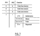
- the baffle configuration differs from the roller shutter configuration by the fact that in the awning configuration we force preferably the motorization to the extreme folding position for guarantee that the canvas is stored in a watertight trunk, so on the contrary, in the roller shutter position, care is taken to stop the motorization below the expected extreme positions.
- the duration of activation of the PHM and PHD lines is controlled, to select from the above three possibilities, reset, shutter mode or shutter mode, controlling the duration actuation of one of the keys 12 or 14 after connecting the two wires PHM and PHD between them, for example using jumper 18.
- the key corresponding to the adjustable stop automatic is activated.
- the up button 12 is activated.
- the apron stops on this stop and the end of stroke is adjusted automatically. This is permanently saved after x stops, for example four stops, within its authorized stop range.
- the controller 24 is adapted to store as a second end stroke the position from which the blackout system is moved before reaching the first limit switch beforehand memorized.
- a first stop is memorized by adjusting the corresponding limit switch using the up and down keys then confirming the memorization of this position without moving the deck by a specific command keys, for example a sequence of three rapid successive presses on the request key towards this stop (i.e. three requests of the button 12 up for setting the upper limit switch or vice versa three quick presses of the down button 14 for storage a low limit switch).
- the second stop is memorized while first by adjusting this limit switch by using the up and descent and once the desired limit switch has been obtained, by actuating the adequate button, so that the apron reaches the end of travel previously memorized.
- the position at from which the shading system is moved, before reaching the first limit switch previously memorized is memorized as as the second end of race.
- the controller 24 is suitable for detecting the duration of activation of the keys 12 and 14 and compare this duration with one or more determined thresholds in order to affect said keys have different functions according to their duration of activation.
- the controller 24 when the controller 24 detects pressing the up / down buttons for a shorter period of time at a threshold, for example 0.5s, it assigns to the actuation of the keys a programming command, without moving the deck. On the other hand, when the controller 24 detects the activation of a key for a time greater than this threshold, for example greater than one second, it attributes to this key a control function for moving the bulkhead.
- a threshold for example 0.5s
- the controller 24 is adapted preferably to ensure an automatic readjustment of the limit switches all Z actions, for example all 256 actions, except in the case where the two limit switches (high and low) are manually adjusted.
- the automatically adjusted limit switch readjustment takes place only within its authorized stopping range.
- This figure shows a control unit (fixed, by wall or portable example) 110 suitable for issuing control codes ascent / stop / descent, by radio waves, when three respective keys 112, 113 and 114, a motor 130 and a card command 120 comprising a means 122 for receiving orders received in coming from the box 110, and which also receives phase signals ⁇ , neutral N, earth T and limit switches FC1 and FC2.
- the exchanges between the transmitter 110 and the receiver 122 can make the object of many embodiments.
- the transmitter 110 and the receiver 122 can be single-channel, the discrimination between the different states resulting from specific codes.
- the transmitter 110 and receiver 122 can be multichannel, each channel corresponding to a specific order. They can also involve a combination of multi-code technologies and multi-channel.
- first configuration for example banne
- second configuration for example rolling shutter
- the aforementioned cable C which contains the wires PH1 and PH2 accommodates also the neutral N and earth T wires, as we have shown on the figure 4.
- a cable C combining the two wires PH1 and PH2 allows to deport the intervention site to control the mode of programming in any suitable place, for example a board power supply, relative to the blackout system trunk which houses the circuit 120 and its receiver 122.
- the device in accordance with the present invention illustrated in Figure 4 works perfectly if the phase and neutral connections from the distribution network are reversed, i.e. if the power line corresponding to the phase is connected on the common point 133 of windings, while the neutral line is then applied to the PH1 line and on the ends of the windings 132, 134 adjacent to the capacitor 136.
- the programming mode can be obtained by connecting the PH1 and PH2 lines between them, independently of a supply line electrical, via any type of connection between the lines concerned, in particular a direct link in the form of a short circuit, a resistive link, a capacitive link, a unidirectional link to diode, etc ...
- the controller 124 is sensitive at the bonding time of the two wires PH1 and PH2.
- the controller 124 can be adapted to detect a connection time between PH1 and PH2 greater than a third threshold, for example a connection duration of the order of 90s, to then control a mode of "sequential" operation. Once this operating mode sequential reached, the PH2 line can be disconnected from the PH1 line. And any subsequent impulse connection between PH1 and PH2, causes following alternate commands: up / stop / down / stop / up / stop / etc ...
- a third threshold for example a connection duration of the order of 90s
- Such a sequential mode of operation can be used by example in the event of a deficiency in the control unit 110.
- the aforementioned impulse connection between the wires PH1 and PH2 can be obtained using a BP push button located on the end of cable C, or by any temporary connection means equivalent, for example a single section of cable fitted with two clamps crocodiles.
- the controller 124 detects the bonding time of the PH2 wire to the phase, and compares this duration of connection to a threshold: above a threshold, for example for a link duration greater than 1s, the controller 124 controls the sequence above alternating ascent / stop / descent / stop / climb etc ..., while only for a link duration below the threshold, for example a duration of link less than 0.5s, the controller 124 assimilates the temporary link of PH2 to the phase, to a programming order likely to bring the control circuit 120 in the previous default configuration. However for security purposes this return to the default configuration is only validated after several brief PH2 connections to the phase, by Example 5 of such links.
- the controller 124 additionally controls a stepwise movement, when a combination key selection is requested.
- a step by step movement the ascent or descent, respectively, can be implemented when one of the up 112 or down 114 keys is pressed while the stop button 113 is previously requested and held in this position.
- Such a step-by-step operating mode allows in particular a precise adjustment of the limit switches.
- driving on the move step by step preferably corresponds to a sequential movement of the deck on a controlled limited amplitude, interspersed with stop phases for sufficient time to allow a user to intervene to stop piloting step by step.
- the interruption stepping is achieved by pressing the stop key on a case (the stop and up or down keys having been previously released, but step by step operation maintained).
- the interruption of stepping piloting can be obtained as soon as the stop and up or down buttons have been released.
- the stop phases have a minimum duration of 20 ms (which leads in practice taking into account the inertia of the assembly, at a physical stop of the apron for several msec).
- the controller is further preferably adapted to memorize an intermediate stop position when a selected combination of keys is pressed, for example the controller can be adapted to store as position intermediate, the position in which the deck is previously located when the up and down keys are pressed simultaneously control box, for 3 seconds.
- the controller memorizes this intermediate value by compared to the upper or lower limit stops of the bulkhead. Therefore the setting an intermediate stop function is preferably only possible if the end of travel stops have been previously set.
- any setting of a new intermediate stop cancels the previous one, unless that special arrangements are not made to memorize several intermediate positions and not just one.
- the controller is suitable for canceling the movement function step by step when an intermediate stop setting is made.
- the limit switches are adjusted according to procedures similar to the arrangements previously described for the order wired.
- the limit switches can be adjusted manually or automatic, depending on the equipment associated with the deck, independently one the other.
- Automatic adjustment of a limit switch is effective after X successive stops, for example 4 successive stops, in the same range.
- An automatic readjustment of the limit switches is carried out the Z actions, for example 256 actions, except in the case where the two ends of stroke (high and low) are manually adjusted.
- the automatically adjusted limit switch readjustment takes place only within its authorized stopping range.
- Manually adjusted limit switch readjustment depending on the automatically set limit position and the length of the apron stroke.
- the system in accordance with this invention makes it possible to mount the gear motor indifferently on a either end of the winding tube.
- the radio control programming mode is preferably adapted to selectively assign or reassign a basic radio command, assignment of a radio command additional, the deletion of an additional radio command, or the deletion of a basic radio command and of one or more command (s) complementary radio (s).
- This programming mode allows you to pair radio commands 110 to the receiver 122, so that a transmitter 110 not recognized by the receiver 122 cannot control circuit 120.
- This mode of programming consists in recognizing the transmitter block 110 and the orders issued by the latter, by the receiver 122, in a sequence preset learning.
- basic radio control a box control 110 suitable for controlling a concealment system specific and “complementary radio control” a control box 110 common to the control of several concealment systems.
- the installer To assign or delete an additional radio command, from preferably the installer must first perform a validation by placing the basic command and additional command in a mode of specific programming then must press a key on the command within a certain period following an actuation of specific validation of the basic order.
Abstract
Description
La présente invention concerne le domaine des systèmes d'occultation motorisés, tels que les stores, bannes, volets, portes ou équivalents, destinés notamment à masquer la lumière et/ou à constituer un barrage contre les intrusions.The present invention relates to the field of systems motorized blackout, such as blinds, banners, shutters, doors or equivalent, intended in particular to mask the light and / or to constitute a barrage against intrusions.
Par la suite l'élément déplaçable de ces systèmes d'occultation sera dénommé, quelque soit sa constitution ou fonction, par le terme générique « tablier », sans que cette expression puisse être considérée comme limitative.Thereafter the movable element of these concealment systems will be called, whatever its constitution or function, by the generic term "Apron", without this expression being able to be considered as limiting.
Plus précisément, la présente invention concerne les moyens de commande de tels systèmes d'occultation.More specifically, the present invention relates to the means of control of such concealment systems.
Par le passé, les systèmes d'occultation du genre précité, étaient entraínés manuellement, entre leur position d'ouverture ou de repliement et leur position de fermeture ou de déploiement, ou encore une position choisie intermédiaire entre celles-ci, par exemple à l'aide d'engrenages actionnés manuellement.In the past, the occultation systems of the aforementioned genre were driven manually, between their open or folded position and their closed or deployed position, or a position chosen intermediate between them, for example using gears manually operated.
Cependant, pour améliorer le confort des utilisateurs, on a proposé déjà depuis de nombreuses années, de motoriser ces systèmes d'occultation.However, to improve user comfort, it has been proposed already for many years, to motorize these systems occultation.
Ainsi la plupart des systèmes d'occultation installés de nos jours sont entraínés par un moteur électrique ou motoréducteur. Plus précisément la plupart des systèmes installés aujourd'hui comprennent un tube d'enroulement sur lequel le tablier du système d'occultation est enroulé, dans sa position "d'ouverture" ou de « repliement », et un motoréducteur à commande électrique associé au tube d'enroulement.So most of the occultation systems installed these days are driven by an electric motor or gear motor. More precisely most of the systems installed today include a winding tube on which the screen of the blackout system is rolled up, in its "open" or "folded" position, and a Electrically operated gearmotor associated with the winding tube.
Ces systèmes d'occultation et leurs moyens de commande ont donné lieu à une littérature abondante.These concealment systems and their control means have gave rise to an abundant literature.
Cependant les moyens jusqu'ici proposés ne donnent pas toujours satisfaction.However, the means hitherto proposed do not always give satisfaction.
La présente invention a maintenant pour but de proposer de nouveaux moyens permettant d'améliorer le confort des utilisateurs et/ou installateurs. The present invention now aims to provide new ways to improve user comfort and / or installers.
Un but important de la présente invention est de proposer des moyens permettant de faciliter le règlage de butées de fin de course pour le tablier.An important object of the present invention is to provide means for facilitating the adjustment of limit stops for the apron.
Un autre but important de la présente invention est de proposer des moyens de commande universels, que ce soit dans une version de type commande filaire ou de type commande radio, aptes à commander tout type de système d'occultation, notamment volet ou banne.Another important object of the present invention is to provide universal control means, whether in a type version wired or radio control type, able to control everything type of concealment system, in particular shutter or awning.
Un autre but important de la présente invention est de proposer des moyens de commande adaptés pour une programmation facile par tout installateur, propre à permettre une adaptation aisée sur tout site d'utilisation.Another important object of the present invention is to provide suitable control means for easy programming by any installer, suitable for easy adaptation on any site of use.
Selon un premier aspect de la présente invention, les buts précités sont atteints grâce à un dispositif de commande comprenant un contrôleur apte à piloter un déplacement pas à pas du tablier, lorsqu'une combinaison choisie de touches est sollicitée.According to a first aspect of the present invention, the aforementioned aims are achieved by a control device comprising a controller able to control a step-by-step movement of the deck, when a combination key selection is requested.
Selon une autre caractéristique avantageuse de la présente invention le pilotage en déplacement pas à pas correspond à un déplacement séquentiel du tablier sur une amplitude limitée contrôlée entrecoupé de phases d'arrêt pendant une durée suffisante pour permettre à un utilisateur d'intervenir pour interrompre le pilotage pas à pas.According to another advantageous characteristic of the present invention piloting on the move step by step corresponds to a sequential movement of the deck over a limited controlled amplitude interspersed with stop phases for a sufficient time to allow a user to intervene to interrupt the piloting step by step.
Selon une autre caractéristique avantageuse de la présente invention, les phases d'arrêt ont une durée minimale de 20 ms.According to another advantageous characteristic of the present invention, the stop phases have a minimum duration of 20 ms.
Selon une autre caractéristique avantageuse de la présente invention, le contrôleur est en outre adapté pour mémoriser une position d'arrêt intermédiaire lorsqu'une combinaison choisie de touches est sollicitée.According to another advantageous characteristic of the present invention, the controller is further adapted to memorize a position intermediate stop when a selected combination of keys is requested.
Selon une autre caractéristique avantageuse de la présente invention, le contrôleur est adapté pour annuler la fonction déplacement pas à pas lorsqu'un réglage d'un arrêt intermédiaire est effectué.According to another advantageous characteristic of the present invention, the controller is adapted to cancel the displacement function not step by step when an intermediate stop setting is made.
Selon un autre aspect important de la présente invention, les buts précités sont atteints grâce à un dispositif de commande comprenant un circuit de commande d'une motorisation, le circuit comportant au moins une entrée susceptible d'être placée sélectivement dans un état de mode programmation par établissement d'un shunt entre cette entrée et un autre conducteur, telle qu'une ligne d'alimentation électrique, et des moyens sensibles à la durée de cet état pour imposer, selon cette durée, un choix dans un menu parmi différents types prédéfinis de programmation.According to another important aspect of the present invention, the aims above are achieved by a control device comprising a motor control circuit, the circuit comprising at least one input capable of being selectively placed in a mode state programming by establishing a shunt between this input and another conductor, such as a power supply line, and means sensitive to the duration of this state to impose, according to this duration, a choice in a menu among different predefined types of programming.
Dans le cadre de la présente invention, le terme « programmation » doit ici être compris dans un sens large, comme englobant notamment toute définition de configuration, mode ou fonction.In the context of the present invention, the term "programming" here must be understood in a broad sense, as including in particular any definition of configuration, mode or function.
De même dans le cadre de la présente invention, le terme « shunt » doit être compris dans un sens général. Il englobe tout type de liaison, notamment une liaison directe sous forme d'un court-circuit, une liaison résistive, une liaison capacitive, une liaison unidirectionnelle à diode, etc ...Similarly in the context of the present invention, the term "shunt" must be understood in a general sense. It includes any type of link, in particular a direct link in the form of a short circuit, a link resistive, a capacitive link, a unidirectional diode link, etc ...
Selon une première mise en oeuvre, dans le cadre d'une application par commande filaire du circuit précité, le dispositif de commande comprend au moins deux moyens d'actionnement qui, lorsqu'ils sont respectivement validés, sollicitent le système d'occultation, l'un vers sa position de fermeture ou déploiement, et l'autre vers sa position d'ouverture ou repliement, caractérisé par le fait qu'il comprend des moyens aptes à imposer un mode de programmation du dispositif de commande lorsqu'une validation simultanée des deux moyens d'actionnement est détectée.According to a first implementation, within the framework of an application by wired control of the aforementioned circuit, the control device comprises at least two actuating means which, when they are respectively validated, request the occultation system, one towards its position closing or deploying, and the other towards its open position or folding, characterized in that it comprises means suitable for impose a programming mode on the control device when a simultaneous validation of the two actuation means is detected.
Selon une deuxième mise en oeuvre, dans le cadre d'une application par commande radio du circuit précité, le dispositif de commande comprend un câble relié au circuit précité comprenant au moins deux fils reliés l'un à une ligne d'alimentation électrique, l'autre à une entrée d'un contrôleur, de sorte que la liaison des deux fils précités impose le passage du circuit de commande dans un mode programmation.According to a second implementation, within the framework of a application by radio control of the aforementioned circuit, the control comprises a cable connected to the aforementioned circuit comprising at least two wires, one connected to a power supply line, the other to an input a controller, so that the connection of the two aforementioned wires requires the passage of the control circuit in a programming mode.
Selon un autre aspect important de la présente invention, les buts précités sont atteints grâce à un dispositif de commande comprenant des moyens de mémorisation des deux fins de course du système d'occultation, correspondant respectivement à une position de fermeture et à une position d'ouverture, caractérisé par le fait que les moyens de mémorisation sont adaptés, après mémorisation préalable d'une première fin de course, pour mémoriser automatiquement en tant que deuxième fin de course, la position à partir de laquelle le système d'occultation est déplacé, dans une phase de programmation, avant d'atteindre ladite première fin de course préalablement mémorisée.According to another important aspect of the present invention, the aims above are achieved by a control device comprising means for memorizing the two limit switches of the concealment system, corresponding respectively to a closed position and a position opening, characterized in that the storage means are adapted, after prior memorization of a first limit switch, to automatically save as the second limit switch, the position from which the occultation system is moved, in a phase of programming, before reaching said first limit switch previously memorized.
Selon un autre aspect important de la présente invention, les buts précités sont atteints grâce à un dispositif de commande comprenant des moyens sensibles à la durée d'activation de moyens de sollicitation, pour assurer des fonctions actives différentes selon que la durée d'activation est inférieure ou supérieure à au moins un seuil déterminé.According to another important aspect of the present invention, the aims above are achieved by a control device comprising means sensitive to the duration of activation of solicitation means, for perform different active functions depending on whether the activation time is less than or greater than at least one determined threshold.
Selon une autre caractéristique avantageuse de la présente invention, les fonctions actives différentes précitées correspondent soit à une fonction de déplacement du système d'occultation, soit à une fonction de mémorisation de fins de course.According to another advantageous characteristic of the present invention, the aforementioned different active functions correspond either to a function of displacement of the occultation system, that is to say a function for memorizing limit switches.
D'autres caractéristiques, buts et avantages de la présente invention apparaítront à la lecture de la description détaillée qui va suivre et en regard des dessins annexés, donnés à titre d'exemples non limitatifs et sur lesquels :
- la figure 1 représente une vue schématique, sous forme de blocs fonctionnels d'un dispositif de commande de système d'occultation, conforme à l'état de la technique, du type commande filaire,
- la figure 2 représente une vue schématique, sous forme de blocs fonctionnels d'un dispositif de commande de système d'occultation, conforme à l'état de la technique, du type commande radio,
- la figure 3 représente une vue schématique, sous forme de blocs fonctionnels d'un dispositif de commande de système d'occultation, conforme à la présente invention, du type commande filaire,
- la figure 4 représente une vue schématique, sous forme de blocs fonctionnels d'un dispositif de commande de système d'occultation, conforme à la présente invention, du type commande radio, et
- les figures 5 à 8 représentent quatre tables de vérité illustrant le procédé de programmation mis en oeuvre dans le cadre de la présente invention.
- FIG. 1 represents a schematic view, in the form of functional blocks of a concealment system control device, conforming to the state of the art, of the wired control type,
- FIG. 2 represents a schematic view, in the form of functional blocks of a concealment system control device, conforming to the state of the art, of the radio control type,
- FIG. 3 represents a schematic view, in the form of functional blocks of a concealment system control device, in accordance with the present invention, of the wired control type,
- FIG. 4 represents a schematic view, in the form of functional blocks of a concealment system control device, in accordance with the present invention, of the radio control type, and
- Figures 5 to 8 show four truth tables illustrating the programming method implemented in the context of the present invention.
Le système connu de type filaire illustré sur la figure 1 annexée
comprend un boítier de commande 10, une carte de commande 20 et un
moteur 30. The known wired type system illustrated in Figure 1 attached
includes a
Le moteur 30 schématisé sur la figure 1 comprend deux bobinages
32, 34 dont un point commun 33 est relié au neutre N tandis que les
secondes extrémités des bobinages 32, 34 sont reliées entre elles par
l'intermédiaire d'un condensateur 36. Par ailleurs, ces secondes extrémités,
en fonctionnement normal, sont susceptibles d'être reliées alternativement à
une ligne de phase. Ainsi, selon le bobinage 32 ou 34 alimenté, le moteur
30 entraíne le système d'occultation vers sa position d'ouverture ou sa
position de fermeture.The
Le boítier de commande 10 illustré sur la figure 1 comprend deux
boutons de commande 12, 14 aptes à piloter un inverseur 16 à trois
positions électriques : une première position O dans laquelle aucun des
deux boutons 12, 14 n'est actionné, deux lignes de sortie PHM et PHD du
boítier 10 sont en l'air et le moteur 30 est à l'arrêt, aucun des deux
bobinages 32, 34 n'étant alimenté; une deuxième position M dans laquelle
le bouton de montée 12 est actionné, l'inverseur 16 est placé sur une
position M et la ligne de sortie PHM est reliée à la phase pour assurer
l'alimentation du bobinage 32 et le déplacement du système d'occultation
vers sa position d'ouverture ; et une troisième position D dans laquelle le
bouton de descente 14 est actionné, l'inverseur 16 est placé sur une
position D et la ligne de sortie PHD est reliée à la phase pour assurer
l'alimentation du bobinage 34 et le déplacement du système d'occultation
vers sa position de fermeture.The
La carte de commande 20 reçoit par l'intermédiaire d'un câble à
quatre fils les lignes de sortie PHM et PHD du boítier 10 ainsi que la ligne
de neutre N et une ligne de terre T. Elle a pour fonction de relier
respectivement les lignes de sortie PHM et PHD aux bobinages 32 et 34. La
carte de commande 20 conditionne cette liaison selon l'état de contacts de
fin de course 37, 38, par exemple montés typiquement en série des lignes
PHM et PHD, pour interrompre l'alimentation des bobinages 32, 34, lorsque
le système d'occultation atteint l'une de ses extrémités de course
autorisées. The
On a représenté sur la figure 2 annexée, un système connu à
commande radio comprenant un boítier 110 fixe ou portable, une carte de
commande 120 et un moteur 130.Is shown in Figure 2 attached, a known system to
radio control comprising a fixed or
Le moteur 130 comprend typiquement deux bobinages 132,134
reliés au neutre sur un point commun et par ailleurs entre eux par
l'intermédiaire d'un condensateur 136 comme indiqué précédemment pour
la figure 1.The
Le boítier 110 comprend typiquement trois touches 112, 114, 113,
utilisées respectivement pour provoquer l'émission d'une onde
électromagnétique codée sollicitant la montée, la descente ou l'arrêt du
système d'occultation associé.The
La carte 120 comporte un récepteur 122 conçu pour détecter ces
ondes, et selon la nature de l'ordre ainsi reçu, assurer l'alimentation de l'un
des bobinages 132, 134, à partir d'une ligne de phase, ou l'arrêt de cette
alimentation. A cette fin, outre la ligne de phase précitée, la carte 120 reçoit
une ligne de neutre N, une ligne de terre T et des signaux FC1 et FC2
représentatifs de fin de course.The
Comme on l'a indiqué précédemment, la présente invention peut s'appliquer soit à un système à commande filaire, soit à un système à commande radio.As indicated above, the present invention can apply either to a wired control system or to a system with radio control.
On va tout d'abord décrire, le système à commande filaire conforme à la présente invention illustré sur la figure 3 annexée.We will first describe, the compliant wired control system to the present invention illustrated in Figure 3 attached.
On retrouve sur cette figure, un boítier de commande 10 conforme à
la figure 1, et un moteur 30 conforme à la figure 1. Le système illustré sur la
figure 3 comprend en outre une carte de commande 20 comprenant un
contrôleur 24. Celui-ci reçoit sur un câble à quatre fils les lignes PHM et
PHD issues du boítier 10 ainsi qu'une ligne de neutre N et une ligne de terre
T. En outre, le contrôleur 24 reçoit des signaux FC1 ou FC2 représentatifs
de fin de course.Found in this figure, a
Dans le cadre de l'invention, les signaux représentatifs de fin de
course peuvent faire l'objet de nombreuses modalités. Ils peuvent être
obtenus à partir de contacteurs mécaniques de fin de course actionnés par
le tablier du système d'occultation, ou encore issus d'une cellule surveillant
l'intensité ou la phase du courant et/ou de la tension dans les bobinages 32,
34. Cependant, de préférence dans le cadre de l'invention, ces signaux FC1
et FC2 sont générés à partir d'un codeur angulaire associé à l'arbre de
sortie du moteur 30, par exemple à partir d'un codeur optique comprenant
une roue codée optiquement (par exemple comprenant une alternance de
segments transparents et opaques ou encore une alternance de segments
réfléchissants et non réfléchissants) associée à une fourchette de détection
optique, ou encore une roue codée magnétiquement associé à un capteur
associé, par exemple une sonde à effet Hall. Par comptage des impulsions
issues de la fourchette ou du capteur, le contrôleur 24 peut connaítre
directement la position du tablier du système d'occultation, par rapport à
une position arbitraire connue d'origine.In the context of the invention, the representative signals at the end of
race can be the subject of many modalities. They can be
obtained from mechanical limit switches actuated by
the apron of the occultation system, or even from a monitoring cell
the intensity or phase of the current and / or voltage in the
Les deux boutons 12, 14 du boítier 10 constituent deux moyens
d'actionnement, qui lorsqu'ils sont respectivement validés, sollicitent le
système d'occultation, l'un vers sa position de fermeture, et l'autre vers sa
position d'ouverture. Comme on l'a indiqué précédemment, selon
l'invention, le contrôleur 24 comprend des moyens aptes à imposer un
mode de programmation du dispositif de commande, lorsqu'ils détectent
une validation simultanée des deux lignes PHM et PHD.The two
En pratique, une telle validation simultanée des deux lignes PHM et
PHD peut être obtenue , par un installateur, en reliant les deux lignes PHM
et PHD entre elles, par exemple à l'aide d'un bornier ou un cavalier 18
prévu spécifiquement à cet effet à l'intérieur du boítier 10 et en sollicitant
l'une des touches 12 ou 14 pour relier ainsi les deux lignes de sortie PHM et
PHD simultanément à la phase.In practice, such a simultaneous validation of the two PHM lines and
PHD can be obtained by an installer by connecting the two PHM lines
and PHD between them, for example using a terminal block or a
Il faut noter cependant ici que le dispositif conforme à la présente
invention fonctionne parfaitement si les connexions de la phase et du neutre
provenant du réseau de distribution électrique sont inversées, c'est à dire si
la ligne d'alimentation correspondant à la phase est reliée sur le point
commun 33 des bobinages, tandis que la ligne de neutre est alors
appliquée sur l'entrée du boítier 10 et par conséquent sur les lignes PHM et
PHD. However, it should be noted here that the device in accordance with this
invention works perfectly if the phase and neutral connections
from the electrical distribution network are reversed, i.e. if
the supply line corresponding to the phase is connected on the point
common 33 of the windings, while the neutral line is then
applied to the input of the
Pour simplifier le descriptif, par la suite lorsque l'on évoquera la validation des lignes PHM et PHD, l'on fera état de leur liaison préférentielle à la « phase ».To simplify the description, later when we discuss the validation of PHM and PHD lines, we will state their preferential link to the "phase".
Il est cependant bien entendu qu'il peut s'agir d'une façon plus générale d'une « ligne d'alimentation électrique », phase ou neutre, si les connexions adéquates sont par ailleurs respectées, ou encore indépendamment d'une telle ligne d'alimentation électrique, tout type de liaison entre les lignes concernées PHM et PHD, notamment une liaison directe sous forme d'un court-circuit, une liaison résistive, une liaison capacitive, une liaison unidirectionnelle à diode, etc ...It is understood, however, that it may be a more general of a “power supply line”, phase or neutral, if the adequate connections are also respected, or independently of such a power supply line, any type of link between the lines concerned PHM and PHD, in particular a link direct in the form of a short circuit, a resistive link, a link capacitive, a unidirectional diode link, etc ...
On obtient alors la table de vérité illustrée sur la figure 5 :
- lorsque les deux lignes PHM et PHD sont en l'air à l'état 0,
aucun bobinage - lorsque seule la ligne PHD est activée à l'état 1, le bobinage 34 est alimenté et le système d'occultation est déplacé vers sa position de déploiement,
- lorsque seule la ligne PHM est activée à l'état 1, le bobinage 32 est alimenté et le système d'occultation est déplacé vers sa position de repliement, et
- lorsque les deux lignes PHM et PHD sont activées à l'état 1, le contrôleur 24 passe en mode programmation, mais interdit l'application simultanée de la tension de phase sur les deux bobinages 32, 34 pour éviter la détérioration du moteur 30.
- when the two lines PHM and PHD are in the air at
state 0, no winding 32, 34 is supplied. The engine is stopped, - when only the PHD line is activated in
state 1, the winding 34 is supplied and the concealment system is moved to its deployment position, - when only the PHM line is activated in
state 1, the winding 32 is supplied and the concealment system is moved to its folded position, and - when the two lines PHM and PHD are activated in
state 1, thecontroller 24 goes into programming mode, but prohibits the simultaneous application of the phase voltage on the twowindings motor 30.
Ainsi le dispositif conforme à la présente invention exploite un état
(liaison simultanée des deux lignes PHM et PHD) qui est interdit selon l'état
de la technique car il est selon celui-ci susceptible de déteriorer le moteur
30.Thus the device according to the present invention exploits a state
(simultaneous connection of the two lines PHM and PHD) which is prohibited depending on the state
of the technique because it is according to this one likely to deteriorate the
Plus précisément encore, comme on l'a indiqué précédemment,
dans le cadre de l'invention, le contrôleur 24 est sensible à la durée de
validation simultanée des deux moyens d'actionnement PHM et PHD.Even more specifically, as previously indicated,
in the context of the invention, the
Comme on l'a illustré sur la figure 6, typiquement le contrôleur 24
compare la durée d'activation simultanée des deux moyens d'actionnement
PHM et PHD à deux seuils de temps T1 et T2. As illustrated in FIG. 6, typically the
Typiquement mais non limitativement, T1 et T2 peuvent être de l'ordre de 5 et 50s.Typically but not limited to, T1 and T2 can be around 5 and 50s.
Ainsi, comme illustré sur la figure 6 :
- lorsque la durée de liaison simultanée à la phase de PHM et PHD est inférieure à T1 (5s), de préférence le contrôleur 24 impose une réinitialisation du circuit de commande (le circuit revient alors dans une configuration usine. On efface alors notamment les éventuelles fins de course spécifiques préalablement mémorisées) ;
- lorsque la durée de liaison simultanée à la phase de PHM et PHD est supérieure à T1 et inférieure à T2 (soit compris par exemple entre 5 et 50s, typiquement de l'ordre de 30s) de préférence le contrôleur 24 impose une première configuration, par exemple une configuration banne ;
- lorsque la durée de liaison simultanée à la phase de PHM et PHD est supérieure à T2 (soit de préférence supérieure à 50s), de préférence le contrôleur 24 impose une seconde configuration, par exemple une configuration volet roulant (il s'agit d'ailleurs de préférence d'un retour à la configuration usine volet roulant).
- when the duration of the simultaneous connection to the phase of PHM and PHD is less than T1 (5 s), preferably the
controller 24 imposes a reinitialization of the control circuit (the circuit then returns to a factory configuration. In this case, any endings are therefore erased specific course previously saved); - when the duration of simultaneous connection to the phase of PHM and PHD is greater than T1 and less than T2 (ie for example between 5 and 50 s, typically of the order of 30 s) preferably the
controller 24 imposes a first configuration, by example a banne configuration; - when the duration of the simultaneous connection to the phase of PHM and PHD is greater than T2 (ie preferably greater than 50 s), preferably the
controller 24 imposes a second configuration, for example a rolling shutter configuration (this is moreover preferably a return to the factory configuration of the roller shutter).
Dans le cadre de l'invention, la configuration banne se distingue de la configuration volet roulant par le fait qu'en configuration banne on force de préférence la motorisation jusqu'à la position de repliement extrême pour garantir un stockage de la toile de banne dans un coffre étanche, alors qu'au contraire, en position volet roulant, on veille à arrêter la motorisation en deçà des positions extrêmes attendues.In the context of the invention, the baffle configuration differs from the roller shutter configuration by the fact that in the awning configuration we force preferably the motorization to the extreme folding position for guarantee that the canvas is stored in a watertight trunk, so on the contrary, in the roller shutter position, care is taken to stop the motorization below the expected extreme positions.
En pratique, la durée d'activation des lignes PHM et PHD est
contrôlée, pour sélectionner parmi les trois possibilités précitées,
réinitialisation, mode banne ou mode volet roulant, en contrôlant la durée
d'actionnement de l'une des touches 12 ou 14 après avoir relié les deux fils
PHM et PHD entre eux, par exemple à l'aide du cavalier 18.In practice, the duration of activation of the PHM and PHD lines is
controlled, to select from the above three possibilities,
reset, shutter mode or shutter mode, controlling the duration
actuation of one of the
On rappelle qu'un dispositif de verrouillage mécanique interdit
l'activation simultanée des deux touches 12 et 14.Remember that a mechanical locking device prohibited
simultaneous activation of the two
Pour régler les fins de course du système, on procède de préférence comme suit. To adjust the limit switches of the system, proceed from preferably as follows.
Distinguons trois cas : 1) le cas de deux butées réglées automatiquement, 2) le cas d'une butée réglée automatiquement et d'une butée réglée manuellement et 3) le cas de deux butées réglées manuellement.Let us distinguish three cases: 1) the case of two set stops 2) in the case of an automatically adjusted stop and a manually adjusted stop and 3) the case of two set stops manually.
Dans le cas de deux butées réglées automatiquement, par exemple
d'un volet roulant équipé d'une butée physique haute et d'une butée
physique basse, on actionne une première touche, par exemple la touche
de montée 12. Le tablier s'arrête sur la butée haute et la fin de course se
règle automatiquement. La fin de course haute est mémorisée de façon
définitive après x arrêts, par exemple quatre arrêts, dans sa plage d'arrêt
autorisée. Pour mémoriser la butée opposée, on actionne l'autre touche,
soit par exemple la touche de descente 14. Le tablier s'arrête sur la butée
basse et la fin de course se règle automatiquement. La fin de course basse
est mémorisée de façon définitive après y arrêts, par exemple quatre arrêts,
dans sa plage d'arrêt autorisé.In the case of two automatically adjusted stops, for example
a roller shutter fitted with a high physical stop and a stop
low physics, you press a first key, for example the key
12. The deck stops on the upper stop and the end of travel
automatically adjusts. The upper limit switch is memorized so
definitive after x stops, for example four stops, in its stop range
authorized. To memorize the opposite stop, press the other key,
or for example the
Dans le cas d'une butée réglée automatiquement et d'une butée
réglée manuellement, la touche correspondant à la butée à réglage
automatique est activée. Par exemple dans le cas d'un volet roulant équipé
d'une butée physique haute, uniquement la touche de montée 12 est
activée. Le tablier s'arrête sur cette butée et la fin de course se règle
automatiquement. Celle-ci est mémorisée de façon définitive après x arrêts,
par exemple quatre arrêts, dans sa plage d'arrêt autorisée. Par contre, pour
assurer le réglage de l'autre fin de course, soit la fin de course basse selon
l'exemple précité, il n'est pas nécessaire d'effectuer y arrêts sur celle-ci. En
effet, le contrôleur 24 est adapté pour mémoriser en tant que deuxième fin
de course la position à partir de laquelle le système d'occultation est
déplacé avant d'atteindre la première fin de course préalablement
mémorisé. Ainsi, par exemple si la fin de course en butée haute a été réglée
et mémorisée préalablement automatiquement, il suffit après avoir atteint la
fin de course basse choisie, d'actionner la touche montée et laisser le
tablier effectuer toute sa course jusqu'à la position butée haute
préalablement mémorisée pour mémoriser en tant que fin de course basse
la position de départ de ce déplacement. In the case of an automatically adjusted stop and a stop
manually adjusted, the key corresponding to the adjustable stop
automatic is activated. For example in the case of an equipped roller shutter
a high physical stop, only the up
Dans le cas de deux butées réglées manuellement, une première
butée est mémorisée en ajustant la fin de course correspondante en
utilisant les touches montée et descente puis en validant la mémorisation de
cette position sans déplacement du tablier par une commande spécifique
des touches, par exemple une séquence de trois appuis successifs rapides
sur la touche de sollicitation vers cette butée (soit trois sollicitations de la
touche 12 montée pour le réglage de la fin de course haute ou inversement
trois sollicitations rapides de la touche 14 de descente pour la mémorisation
d'une fin de course basse). Puis, la deuxième butée est mémorisée tout
d'abord en ajustant cette fin de course par utilisation des touches montée et
descente et une fois la fin de course recherchée obtenue, en actionnant la
touche adéquate, de sorte que le tablier atteigne la fin de course
préalablement mémorisée. Là encore, comme précédemment, la position à
partir de laquelle le système d'occultation est déplacé, avant d'atteindre la
première fin de course préalablement mémorisée, est mémorisée en tant
que deuxième fin de course.In the case of two manually adjusted stops, a first
stop is memorized by adjusting the corresponding limit switch
using the up and down keys then confirming the memorization of
this position without moving the deck by a specific command
keys, for example a sequence of three rapid successive presses
on the request key towards this stop (i.e. three requests of the
On notera que pour permettre le fonctionnement précité, le
contrôleur 24 est adapté pour détecter la durée d'activation des touches 12
et 14 et comparer cette durée à un ou des seuils déterminés afin d'affecter
auxdites touches des fonctions différentes selon leur durée d'activation.Note that to allow the above operation, the
Plus précisément encore, lorsque le contrôleur 24 détecte
l'actionnement des touches montée/descente pendant une durée inférieure
à un seuil, par exemple 0,5s, il attribue à l'actionnement des touches une
commande de programmation, sans déplacement du tablier. Par contre,
lorsque le contrôleur 24 décèle l'activation d'une touche pendant un temps
supérieur à ce seuil, par exemple supérieur à une seconde, il attribue à
cette touche une fonction de commande en déplacement du tablier.More precisely still, when the
Par ailleurs dans le cadre de l'invention, le contrôleur 24 est adapté
de préférence pour assurer un réajustement automatique des fins de course
toutes les Z actions, par exemple toutes les 256 actions, sauf dans le cas
où les deux fins de course (haute et basse) sont réglées manuellement.Furthermore, in the context of the invention, the
Le réajustement de la fin de course réglée automatiquement s'effectue uniquement dans sa plage d'arrêt autorisée. The automatically adjusted limit switch readjustment takes place only within its authorized stopping range.
Le réajustement de la fin de course réglée manuellement s'effectue en fonction de la position de la fin de course réglée automatiquement et de la longueur de la course du tablier (dans le cadre de la présente invention, on considère en effet que la hauteur du tablier est constante).Manually adjusted limit switch readjustment depending on the automatically set limit position and the length of the deck travel (in the context of the present invention, we consider that the deck height is constant).
On va maintenant décrire, le système à commande radio conforme à la présente invention illustré sur la figure 4 annexée.We will now describe, the radio controlled system conforms to the present invention illustrated in Figure 4 appended.
On retrouve sur cette figure un boitier de commande (fixe, par
exemple mural, ou portable) 110 apte à émettre des codes de commande
montée/arrêt/descente, par ondes radio, lors d'actionnement de trois
touches respectives 112, 113 et 114, un moteur 130 et une carte de
commande 120 comportant un moyen 122 de réception des ordres reçus en
provenance du boitier 110, et qui reçoit par ailleurs des signaux de phase ϕ,
neutre N, terre T et de fins de course FC1 et FC2.This figure shows a control unit (fixed, by
wall or portable example) 110 suitable for issuing control codes
ascent / stop / descent, by radio waves, when three
Les échanges entre l'émetteur 110 et le récepteur 122 peuvent faire
l'objet de nombreux modes de réalisation. L'émetteur 110 et le récepteur
122 peuvent être monocanaux, la discrimination entre les différents états
résultant de codes spécifiques. L'émetteur 110 et le récepteur 122 peuvent
être multicanaux, chaque canal correspondant à un ordre spécifique. Ils
peuvent également faire intervenir une combinaison des technologies multi-codes
et multi-canaux.The exchanges between the
Le cas échéant le choix dans un menu de programmation, entre un
mode initialisation, configuration première par exemple banne et
configuration seconde par exemple volet roulant, pourrait être obtenu par
détection de la durée d'activation simultanée des deux touches 112 et 114,
de manière analogique aux dispositions précédemment décrites en regard
de la figure 3.If necessary, the choice in a programming menu, between a
initialization mode, first configuration for example banne and
second configuration for example rolling shutter, could be obtained by
detection of the duration of simultaneous activation of the two
Cependant dans le cadre de la présente invention, on préfère, pour
éviter une reprogrammation non intentionnelle, assurer la sélection de
programmation à l'aide de moyens spécifiques constitués d'un cable C
comportant au moins deux fils : l'un PH1 destiné à être relié à la phase côté
alimentation secteur et à la carte d'alimentation du circuit de commande
120, et l'autre PH2 destiné à être relié à une entrée spécifique du contrôleur
124. However, in the context of the present invention, it is preferred, for
avoid unintentional reprogramming, ensure selection of
programming using specific means consisting of a C cable
comprising at least two wires: one PH1 intended to be connected to the side phase
mains supply and to the control
Là encore il faut noter que le dispositif fonctionne parfaitement si les connexions entre neutre et phase sont inversées.Again it should be noted that the device works perfectly if the connections between neutral and phase are reversed.
En pratique, le câble précité C qui contient les fils PH1 et PH2 loge également les fils de neutre N et de terre T, comme on l'a schématisé sur la figure 4.In practice, the aforementioned cable C which contains the wires PH1 and PH2 accommodates also the neutral N and earth T wires, as we have shown on the figure 4.
Comme on l'a illustré sur la figure 7 :
- lorsque le fil
PH 1 n'est pas alimenté par la phase,état 0, quel que soit l'état du fil PH2,le circuit 120 n'est pas alimenté, - lorsque le fil PH1 est seul alimenté, soit PH1 à 1 et PH2 à 0,
le circuit 120 est alimenté, en attente d'ordre en provenance du boitier 110, en fonctionnement normal, et - lorsque les deux fils PH1 et PH2 sont reliés simultanément à la phase,
état 1,le circuit 120 est placé dans un mode de programmation.
- when the
PH 1 wire is not supplied by the phase,state 0, whatever the state of the PH2 wire, thecircuit 120 is not supplied, - when the wire PH1 is only supplied, ie PH1 at 1 and PH2 at 0, the
circuit 120 is supplied, awaiting an order from theunit 110, in normal operation, and - when the two wires PH1 and PH2 are simultaneously connected to the phase,
state 1, thecircuit 120 is placed in a programming mode.
De manière comparable au mode de réalisation précédemment décrit en regard des figures 3, 5 et 6, il suffit donc à un installateur de relier les fils PH1 et PH2, à la phase, à l'extrémité accessible du câble C, pour imposer un mode de programmation.Comparably to the embodiment previously described with reference to Figures 3, 5 and 6, it is enough for an installer to connect PH1 and PH2 wires, in phase, at the accessible end of cable C, for impose a programming mode.
Et l'utilisation d'un câble C regroupant les deux fils PH1 et PH2
permet de déporter le site d'intervention pour piloter le mode de
programmation en tout lieu approprié, par exemple un tableau
d'alimentation, par rapport au coffre du système d'occultation qui loge le
circuit 120 et son récepteur 122.And the use of a cable C combining the two wires PH1 and PH2
allows to deport the intervention site to control the mode of
programming in any suitable place, for example a board
power supply, relative to the blackout system trunk which houses the
Il faut noter également ici que, de manière comparable au mode de
réalisation à commande filaire précédemment décrit, le dispositif conforme à
la présente invention illustré sur la figure 4, fonctionne parfaitement si les
connexions de la phase et du neutre provenant du réseau de distribution
électrique sont inversées, c'est à dire si la ligne d'alimentation
correspondant à la phase est reliée sur le point commun 133 des
bobinages, tandis que la ligne de neutre est alors appliquée sur la ligne PH1
et sur les extrémités des bobinages 132, 134 adjacentes au condensateur
136.It should also be noted here that, in a manner comparable to the mode of
wired control embodiment previously described, the device in accordance with
the present invention illustrated in Figure 4, works perfectly if the
phase and neutral connections from the distribution network
are reversed, i.e. if the power line
corresponding to the phase is connected on the
Par ailleurs le mode programmation peut être obtenu en reliant les lignes PH1 et PH2 entre elles, indépendamment d'une ligne d'alimentation électrique, par l'intermédiaire de tout type de liaison entre les lignes concernées, notamment une liaison directe sous forme d'un court-circuit, une liaison résistive, une liaison capacitive, une liaison unidirectionnelle à diode, etc...In addition, the programming mode can be obtained by connecting the PH1 and PH2 lines between them, independently of a supply line electrical, via any type of connection between the lines concerned, in particular a direct link in the form of a short circuit, a resistive link, a capacitive link, a unidirectional link to diode, etc ...
Par conséquent la mention de liaison à la « phase » utilisée par la suite pour simplifier le descriptif, devra être considérée comme une liaison préférentielle, mais non limitative.Consequently the mention of binding to the "phase" used by the continued to simplify the description, should be considered as a link preferential, but not limiting.
Par ailleurs là encore de préférence, le contrôleur 124 est sensible
au temps de liaison des deux fils PH1 et PH2.Also here again preferably, the
Typiquement, mais non limitativement :
- pour une durée de liaison de PH1 et PH2 inférieure à un seuil T1, par exemple une durée de liaison de l'ordre de 5s, le contrôleur 124 passe dans un mode de réinitialisation, rétablissant le cablage d'origine,
- pour une durée de liaison de PH1 et PH2 comprise entre deux seuils T1 et T2, par exemple une durée de liaison de l'ordre de 30s, le contrôleur 124 passe dans une première configuration, par exemple une configuration banne, et
- pour une durée de liaison de PH1 et PH2 supérieure à un deuxième seuil T2, par exemple une durée de liaison de l'ordre de 60s, le contrôleur passe dans une deuxième configuration, par exemple une configuration volet roulant.
- for a connection duration of PH1 and PH2 below a threshold T1, for example a connection duration of the order of 5 s, the
controller 124 goes into a reset mode, restoring the original wiring, - for a connection duration of PH1 and PH2 comprised between two thresholds T1 and T2, for example a connection duration of the order of 30 s, the
controller 124 goes into a first configuration, for example a banne configuration, and - for a connection duration of PH1 and PH2 greater than a second threshold T2, for example a connection duration of the order of 60s, the controller goes into a second configuration, for example a roller shutter configuration.
On notera que comme illustré sur la figure 7, dans le cadre de la
présente invention, le contrôleur 124 peut être adapté pour détecter une
durée de liaison entre PH1 et PH2 supérieure à un troisième seuil, par
exemple une durée de liaison de l'ordre de 90s, pour piloter alors un mode
de fonctionnement « séquentiel ». Une fois ce mode de fonctionnement
séquentiel atteint, la ligne PH2 peut être déconnectée de la ligne PH1. Et
toute liaison impulsionnelle ultérieure entre PH1 et PH2, entraíne les
commandes alternées suivantes : montée / stop / descente / stop / montée /
stop / etc...Note that as illustrated in Figure 7, in the context of
present invention, the
Un tel mode de fonctionnement séquentiel peut être utilisé par
exemple en cas de déficience du boitier de commande 110. Such a sequential mode of operation can be used by
example in the event of a deficiency in the
En pratique la liaison impulsionnelle précitée entre les fils PH1 et PH2 peut être obtenue à l'aide d'un bouton poussoir BP disposé sur l'extrémité du cable C, ou encore par tous moyens de liaison temporaire équivalent, par exemple un simple tronçon de cable équipé de deux pinces crocodiles.In practice the aforementioned impulse connection between the wires PH1 and PH2 can be obtained using a BP push button located on the end of cable C, or by any temporary connection means equivalent, for example a single section of cable fitted with two clamps crocodiles.
De préférence l'accès à l'extrémité du fil PH2 et au bouton poussoir BP, lorsque celui-ci existe, est protégé, par exemple par une clé, pour éviter une manipulation intempestive de ceux-ci et garantir ainsi leur manipulation par un installateur compétent.Preferably access to the end of the PH2 wire and to the push button BP, when it exists, is protected, for example by a key, to avoid untimely handling of these and thus guarantee their handling by a competent installer.
Par ailleurs pendant le fonctionnement séquentiel, de préférence le
contrôleur 124 détecte la durée de liaison du fil PH2 à la phase, et compare
cette durée de liaison à un seuil : en dessus d'un seuil, par exemple pour
une durée de liaison supérieure à 1s, le contrôleur 124 pilote la séquence
précitée alternée de montée / arrêt / descente / arrêt / montée etc..., tandis
que pour une durée de liaison inférieure au seuil, par exemple une durée de
liaison inférieure à 0,5s, le contrôleur 124 assimile la liaison temporaire de
PH2 à la phase, à un ordre de programmation susceptible de ramener le
circuit de commande 120 dans la configuration par défaut antérieure.
Cependant à des fins de sécurité ce retour à la configuration par défaut
n'est validé qu'après plusieurs brèves liaisons de PH2 à la phase, par
exemple 5 de telles liaisons.Furthermore during sequential operation, preferably the
Dans le cadre de la présente invention, le boitier 110 comporte en outre un commutateur à deux positions 116. Celui-ci n'est accessible qu'à l'installateur ou un utilisateur averti, après ouverture du boitier 110. Il est utilisé pour moduler les codes émis par le boitier 110 pour distinguer entre un mode de fonctionnement normal et un mode programmation, par exemple sur les bases suivantes :
commutateur 116 dans une première position de repos: mode de fonctionnement « normal »,commutateur 116 dans la seconde position : mode de programmation et de réglage des fins de course, et- appui sur la touche arrêt 114, puis tout en maintenant celle-ci, placement du commutateur 116 dans la seconde position : mode de programmation des commandes radio.
- switch 116 in a first rest position: "normal" operating mode,
- switch 116 in the second position: mode of programming and adjustment of the limit switches, and
- press the
stop button 114, then while holding it, place theswitch 116 in the second position: radio command programming mode.
Dans le fonctionnement normal :
- l'appui sur la
touche montée 112 sollicite le tablier à la montée et celui-ci s'arrête sur sa fin de course haute, - l'appui sur la
touche arrêt 113 stoppe le tablier dans son déplacement, et - l'appui sur la touche descente 114 sollicite le tablier à la descente et celui-ci s'arrête sur sa fin de course basse.
- pressing the
climb button 112 requests the apron to climb and it stops at its upper end position, - pressing the
stop button 113 stops the apron in its movement, and - pressing the
descent button 114 requests the apron when it descends and it stops at its low end of travel.
De préférence dans le cadre de la présente invention, le contrôleur
124 pilote de plus un déplacement pas à pas, lorsqu'une combinaison
choisie de touches est sollicitée. Par exemple un déplacement pas à pas à
la montée, respectivement à la descente, peut être mis en oeuvre lorsque
l'une des touches montée 112 ou descente 114 est sollicitée alors que la
touche arrêt 113 est préalablement sollicitée et maintenue dans cette
position. Un tel mode de fonctionnement pas à pas permet en particulier un
réglage précis des fins de course.Preferably in the context of the present invention, the
Dans le cadre de la présente invention le pilotage en déplacement pas à pas correspond de préférence à un déplacement séquentiel du tablier sur une amplitude limitée contrôlée, entrecoupé de phases d'arrêt pendant une durée suffisante pour permettre à un utilisateur d'intervenir pour interrompre le pilotage pas à pas.In the context of the present invention, driving on the move step by step preferably corresponds to a sequential movement of the deck on a controlled limited amplitude, interspersed with stop phases for sufficient time to allow a user to intervene to stop piloting step by step.
De préférence dans le cadre de la présente invention, l'interruption du pilotage pas à pas est obtenue en appuyant sur la touche arrêt d'un boitier (les touches arrêt et montée ou descente ayant été préalablement relachées, mais le fonctionnement pas à pas maintenu). Cependant en variante, l'interruption du pilotage pas à pas peut être obtenue dès que les touches arrêt et montée ou descente ont été relachées.Preferably in the context of the present invention, the interruption stepping is achieved by pressing the stop key on a case (the stop and up or down keys having been previously released, but step by step operation maintained). However in variant, the interruption of stepping piloting can be obtained as soon as the stop and up or down buttons have been released.
Les phases d'arrêt ont une durée minimale de 20 ms (ce qui conduit en pratique compte tenu de l'inertie de l'ensemble, à un arrêt physique du tablier pendant plusieurs msec).The stop phases have a minimum duration of 20 ms (which leads in practice taking into account the inertia of the assembly, at a physical stop of the apron for several msec).
Dans le cadre de la présente invention, le contrôleur est en outre adapté de préférence pour mémoriser une position d'arrêt intermédiaire lorsqu'une combinaison choisie de touches est sollicitée, par exemple le contrôleur peut être adapté pour mémorisrer en tant que position intermédiaire, la position dans laquelle est préalablement situé le tablier lorsque l'on appuie simultanément sur les touches montée et descente d'un boitier de commande, pendant 3 secondes.In the context of the present invention, the controller is further preferably adapted to memorize an intermediate stop position when a selected combination of keys is pressed, for example the controller can be adapted to store as position intermediate, the position in which the deck is previously located when the up and down keys are pressed simultaneously control box, for 3 seconds.
De préférence le contrôleur mémorise cette valeur intermédiaire par rapport aux butées de fin de course haute ou basse du tablier. De ce fait la fonction réglage d'un arrêt intermédiaire n'est de préférence possible que si les butées de fin de course ont été préalablement réglées.Preferably the controller memorizes this intermediate value by compared to the upper or lower limit stops of the bulkhead. Therefore the setting an intermediate stop function is preferably only possible if the end of travel stops have been previously set.
Par ailleurs de préférence dans le cadre de la présente invention, tout réglage d'un nouvel arrêt intermédiaire annule le précédent, à moins que des dispositions particulières ne soient prévues pour mémoriser plusieurs positions intermédiaires et non pas une seule.Furthermore preferably within the framework of the present invention, any setting of a new intermediate stop cancels the previous one, unless that special arrangements are not made to memorize several intermediate positions and not just one.
Selon une autre caractéristique de la présente invention, le contrôleur est adapté pour annuler la fonction déplacement pas à pas lorsqu'un réglage d'un arrêt intermédiaire est effectué.According to another characteristic of the present invention, the controller is suitable for canceling the movement function step by step when an intermediate stop setting is made.
Le réglage des fins de course est réalisé selon des modalités similaires aux dispositions précédemment décrites pour la commande filaire.The limit switches are adjusted according to procedures similar to the arrangements previously described for the order wired.
Les fins de course peuvent être réglées de façon manuelle ou automatique, selon l'équipement associé au tablier, indépendamment l'une de l'autre.The limit switches can be adjusted manually or automatic, depending on the equipment associated with the deck, independently one the other.
Le règlage automatique d'une fin de course est effectif après X arrêts successifs, par exemple 4 arrêts successifs, dans une même plage.Automatic adjustment of a limit switch is effective after X successive stops, for example 4 successive stops, in the same range.
Un réajustement automatique des fins de course s'effectue toutes les Z actions, par exemple 256 actions, sauf dans le cas où les deux fins de course (haute et basse) sont réglées manuellement.An automatic readjustment of the limit switches is carried out the Z actions, for example 256 actions, except in the case where the two ends of stroke (high and low) are manually adjusted.
Le réajustement de la fin de course réglée automatiquement s'effectue uniquement dans sa plage d'arrêt autorisée.The automatically adjusted limit switch readjustment takes place only within its authorized stopping range.
Le réajustement de la fin de course réglée manuellement s'effectue en fonction de la position de la fin de course réglée automatiquement et de la longueur de la course du tablier. Manually adjusted limit switch readjustment depending on the automatically set limit position and the length of the apron stroke.
La reconnaissance automatique des fins de course est prioritaire sur la reconnaissance manuelle des fins de course. Pour tout réajustement sur butée physique, qu'il provienne cycliquement (toutes les Z actions) ou qu'il soit lié à un décalage du à la mécanique du tablier ou à une erreur de comptage, un réajustement de la butée opposée sera opéré.Automatic recognition of limit switches has priority on manual recognition of limit switches. For any readjustment on physical stop, whether it comes cyclically (all Z actions) or whether it is related to a shift due to the mechanics of the deck or to an error in counting, a readjustment of the opposite stop will be made.
Par ailleurs il faut distinguer là encore les 3 cas 1) de 2 butées (physiques) réglées automatiquement, 2) d'une butée (physique) réglée automatiquement et d'une butée (ou position) réglée manuellement et 3) de deux butées (ou positions) réglées manuellement.In addition, we must again distinguish the 3 cases 1) from 2 stops (physical) set automatically, 2) a (physical) set stop automatically and a manually adjusted stop (or position) and 3) two stops (or positions) manually adjusted.
Dans le cas de 2 butées réglées automatiquement, par exemple d'un volet roulant équipé d'une butée physique haute et d'une butée physique basse, l'installateur procède comme suit :
- le commutateur 116 du boitier 110 est placé en mode normal,
- la touche montée 112 est appuyée, le tablier s'arrête sur sa butée haute et la fin de course se règle automatiquement, (cette fin de course haute est mémorisée de façon définitive après 4 arrêts dans sa plage d'arrêt autorisée),
- la touche descente 114 est appuyée, le tablier s'arrête sur sa butée basse et la fin de course se règle automatiquement, (cette fin de course basse est mémorisée de façon définitive après 4 arrêts dans sa plage d'arrêt autorisée).
- the
switch 116 of thehousing 110 is placed in normal mode, - the up
key 112 is pressed, the apron stops at its upper stop and the limit switch is adjusted automatically (this upper limit switch is permanently memorized after 4 stops in its authorized stop range), - the
descent key 114 is pressed, the apron stops at its lower stop and the limit switch is adjusted automatically (this lower limit switch is permanently memorized after 4 stops in its authorized stop range).
Dans le cas d'une butée réglée automatiquement et d'une butée réglée manuellement, par exemple d'un volet roulant équipé d'une butée physique haute uniquement, l'installateur procède comme suit :
- le commutateur 116 du boitier 110 est placé en mode normal,
- la touche montée 112 est appuyée, le tablier s'arrête sur sa butée haute et la fin de course se règle automatiquement, (cette fin de course haute est mémorisée de façon définitive après 4 arrêts dans sa plage d'arrêt autorisée),
- les touches
montée 112 et descente 114 sont sollicitées pour ajuster la butée de fin de course basse recherchée, et lorsque celle-ci est atteinte :- soit la touche montée 112 est appuyée jusqu'à ce que le tablier atteigne sa fin de course haute précédemment mémorisée, ce qui provoque la mémorisation automatique de la position basse de départ en tant que fin de course basse,
- soit le commutateur 116 est placé en position programmation fins
de course, et l'appui sur la touche descente 114 pendant un temps
supérieur à un seuil, par exemple de l'ordre de 3s, entraine la mémorisation
de la fin de course basse ainsi obtenue (bien évidemment de manière
symétrique il s'agit de la
touche montée 112 sollicitée pendant 3 s pour mémoriser la fin de course haute).
- the
switch 116 of thehousing 110 is placed in normal mode, - the up
key 112 is pressed, the apron stops at its upper stop and the limit switch is adjusted automatically (this upper limit switch is permanently memorized after 4 stops in its authorized stop range), - the up 112 and down 114 keys are used to adjust the desired low end stop, and when this is reached:
- either the up
key 112 is pressed until the apron reaches its previously memorized high limit switch, which causes the automatic starting low position to be memorized as a low limit switch, - either the
switch 116 is placed in the end-of-travel programming position, and pressing thedescent button 114 for a time greater than a threshold, for example of the order of 3 s, results in the memorization of the low end-of-travel thus obtained (obviously symmetrically, this is the upbutton 112 pressed for 3 s to memorize the upper limit switch).
- either the up
Dans le cas de deux butées réglées manuellement, par exemple d'un volet roulant non équipé de butée physique et dans l'hypothèse d'une fin de course haute réglée avant la fin de course basse, l'installateur procède comme suit :
- le commutateur 116 du boitier 110 est placé en mode normal,
- les touches
montée 112 et descente 114 sont sollicitées pour ajuster la butée de fin de course haute recherchée, et lorsque celle-ci est atteinte :- le commutateur 116 est placé en position programmation fins de course, et l'appui sur la touche montée 112 pendant un temps supérieur à un seuil, par exemple de l'ordre de 3s, entraine la mémorisation de la fin de course haute ainsi obtenue (bien évidemment de manière symétrique il s'agit de la touche descente 114 sollicitée pendant 3 s pour mémoriser la fin de course basse),
- le commutateur 116 du boitier 110 est placé en mode normal,
- les touches
montée 112 et descente 114 sont sollicitées pour ajuster la butée de fin de course basse recherchée, et lorsque celle-ci est atteinte :- soit la touche montée 112 est appuyée jusqu'à ce que le tablier atteigne sa fin de course haute précédemment mémorisée, ce qui provoque la mémorisation automatique de la position basse de départ en tant que fin de course basse,
- soit le commutateur 116 est placé en position programmation fins
de course, et l'appui sur la touche descente 114 pendant un temps
supérieur à un seuil, par exemple de l'ordre de 3s, entraine la mémorisation
de la fin de course basse ainsi obtenue (bien évidemment de manière
symétrique il s'agit de la
touche montée 112 sollicitée pendant 3 s pour mémoriser la fin de course haute).
- the
switch 116 of thehousing 110 is placed in normal mode, - the up 112 and down 114 keys are used to adjust the desired high end stop, and when this is reached:
- the
switch 116 is placed in the end-of-travel programming position, and pressing theup key 112 for a time greater than a threshold, for example of the order of 3 s, results in the memorization of the high end-of-travel thus obtained ( obviously symmetrically, this is thedown button 114 pressed for 3 s to memorize the low limit switch), - the
switch 116 of thehousing 110 is placed in normal mode, - the up 112 and down 114 keys are used to adjust the desired low end stop, and when this is reached:
- either the up
key 112 is pressed until the apron reaches its previously memorized high limit switch, which causes the automatic starting low position to be memorized as a low limit switch, - either the
switch 116 is placed in the end-of-travel programming position, and pressing thedescent button 114 for a time greater than a threshold, for example of the order of 3 s, results in the memorization of the low end-of-travel thus obtained (obviously symmetrically, this is the upbutton 112 pressed for 3 s to memorize the upper limit switch).
- either the up
- the
Pour supprimer les règlages de fins de course, il suffit de placer le
commutateur 116 en position programmation fins de course et d'appuyer
sur la touche arrêt 113 pendant un temps supérieur à un seuil, par exemple
de l'ordre de 3s.To remove the limit switch settings, simply place the
Il faut noter que tant dans le mode de commande filaire que dans le cas du mode de commande radio, le système conforme à la présente invention permet de monter indifféramment le motoréducteur sur une extrémité ou l'autre du tube d'enroulement. Il est prévu pour cela des moyens aptes à inverser le sens de rotation du moteur, si nécessaire.It should be noted that both in the wired control mode and in the radio control mode, the system in accordance with this invention makes it possible to mount the gear motor indifferently on a either end of the winding tube. For this purpose, means capable of reversing the direction of rotation of the motor, if necessary.
De préférence dans le cas de la commande par liaison radio, l'installateur procède alors comme suit :
- le commutateur 116 est placé en mode réglagles fins de course, et
- la touche arrêt 113 est sollicitée pendant un temps déterminé, par exemple de l'ordre de 1s et tout en la maintenant, la touche montée 112 est sollicitée pendant une durée supérieure à un seuil, par exemple de l'ordre de 3s.
- the
switch 116 is placed in limit switch setting mode, and - the
stop button 113 is pressed for a determined time, for example of the order of 1s and while holding it, the upbutton 112 is pressed for a duration greater than a threshold, for example of the order of 3s.
On notera que dans le cas de la commande par liaison filaire, il suffit
à l'installateur d'inverser la connexion des deux fils PHM et PHD en sortie
du boítier 10.Note that in the case of control by wire connection, it suffices
the installer to reverse the connection of the two PHM and PHD wires at the
Le mode de programmation des commandes radio est de préférence adapté pour assurer sélectivement une affectation ou réaffectation d'une commande radio de base, une affectation d'une commande radio complémentaire, la suppression d'une commande radio complémentaire, ou la suppression d'une commande radio de base et d'une ou de commande(s) radio complémentaire(s).The radio control programming mode is preferably adapted to selectively assign or reassign a basic radio command, assignment of a radio command additional, the deletion of an additional radio command, or the deletion of a basic radio command and of one or more command (s) complementary radio (s).
Ce mode de programmation permet d'apparier les commandes radio
110 au récepteur 122, de sorte qu'un émetteur 110 non reconnu par le
récepteur 122 ne puisse pas piloter le circuit 120. Ce mode de
programmation consiste à faire reconnaítre le bloc émetteur 110 et les
ordres émis par ce dernier, par le récepteur 122, selon une séquence
d'apprentissage prédéfinie. This programming mode allows you to pair radio commands
110 to the
On appelle généralement « commande radio de base » un boitier de
commande 110 adapté pour commander un système d'occultation
spécifique et « commande radio complémentaire » un boitier de commande
110 commun à la commande de plusieurs systèmes d'occultation.Generally called "basic radio control" a
Pour affecter ou réafffecter une commande radio de base, de préférence, l'installateur doit solliciter une touche de la commande dans un certain délai consécutif à une phase de réinitialisation. Pour cela de préférence l'installateur procède comme suit :
- le commutateur 116 de cette commande est placé en position « mode normal »,
- les fils PH1 et PH2 sont reliés pendant 5s pour opérer une réinitialisation,
le circuit 120 est alors en attente de programmation pendant 60s,- il suffit alors d'appuyer sur la touche arrêt 113 par exemple pendant 1s,
pour adresser une trame de
reconnaissance au récepteur 122, - le mode programmation est quitté dès que la trame est reçue.
- the
switch 116 of this control is placed in the "normal mode" position, - PH1 and PH2 wires are connected for 5s to carry out a reset,
-
circuit 120 is then awaiting programming for 60s, - it then suffices to press the
stop key 113 for example for 1 second, to send a recognition frame to thereceiver 122, - programming mode is exited as soon as the frame is received.
Pour affecter ou supprimer une commande radio complémentaire, de préférence l'installateur doit tout d'abord opérer une validation en plaçant la commande de base et la commande complémentaire dans un mode de programmation spécifique puis doit solliciter une touche de la commande complémentaire dans un certain délai consécutif à un actionnement de validation spécifique de la commande de base.To assign or delete an additional radio command, from preferably the installer must first perform a validation by placing the basic command and additional command in a mode of specific programming then must press a key on the command within a certain period following an actuation of specific validation of the basic order.
Plus précisément de préférence pour affecter une commande radio complémentaire, l'installateur procède comme suit :
- la commande radio de base et la commande radio complémentaire sont placées en position « programmation commandes radio»,
- la touche montée 112 de la commance radio de base est activée pendant 3s,
le circuit 120 est alors en attente de programmation pendant 60s,- il suffit alors d'appuyer sur la touche arrêt 113 de la commande radio
complémentaire par exemple pendant 1s, pour adresser une trame de
reconnaissance au récepteur 122, - le mode programmation est quitté dès que cette trame est reçue.
- the basic radio control and the additional radio control are placed in the "radio control programming" position,
- the up
button 112 of the basic radio command is activated for 3s, -
circuit 120 is then awaiting programming for 60s, - it then suffices to press the
stop key 113 of the complementary radio control for example for 1 second, to send a recognition frame to thereceiver 122, - programming mode is exited as soon as this frame is received.
Pour supprimer une commande radio complémentaire, l'installateur procède comme suit :
- la commande radio de base et la commande radio complémentaire sont placées en position « programmation commandes radio»,
- la touche descente 114 de la commance radio de base est activée pendant 3s,
le circuit 120 est alors en attente de programmation pendant 60s,- il suffit alors d'appuyer sur la touche arrêt 113 de la commande radio
complémentaire par exemple pendant 1s, pour adresser une trame de
reconnaissance au récepteur 122, - le mode programmation est quitté dès que cette trame est reçue.
- the basic radio control and the additional radio control are placed in the "radio control programming" position,
- the
down button 114 of the basic radio control is activated for 3s, -
circuit 120 is then awaiting programming for 60s, - it then suffices to press the
stop key 113 of the complementary radio control for example for 1 second, to send a recognition frame to thereceiver 122, - programming mode is exited as soon as this frame is received.
Pour supprimer la commande de radio de base et la ou les commandes radio complémentaires, l'installateur procède comme suit :
- la commande radio de base est placée en position « programmation commandes radio»,
- la touche arrêt 113 de la commance radio de base est activée pendant 3s,
le circuit 120 est alors en attente de programmation pendant 60s afin d'autoriser la réaffectation d'une commande radio de base par réception d'une nouvelle trame de reconnaissance si l'utilisateur le souhaite,- le mode programmation est quitté dès que cette trame est reçue.
- the basic radio control is placed in the "radio control programming" position,
- the
stop key 113 of the basic radio command is activated for 3s, - the
circuit 120 is then awaiting programming for 60s in order to authorize the reassignment of a basic radio command by reception of a new recognition frame if the user so wishes, - programming mode is exited as soon as this frame is received.
La synthèse des commandes qui viennent d'être décrites pour la commande radio est illustrée sur la figure 8.The summary of the commands which have just been described for the radio control is illustrated in figure 8.
Bien entendu la présente invention n'est pas limitée aux modes de réalisation particuliers qui viennent d'être décrits, en particulier aux valeurs de temps ou encore aux séquences précises d'actionnement qui ont été mentionnées, mais s'étend à toutes variantes conformes à son esprit.Of course, the present invention is not limited to the modes of particular achievements which have just been described, in particular the values time or the specific actuation sequences that have been mentioned, but extends to all variants according to its spirit.
Claims (10)
Applications Claiming Priority (4)
| Application Number | Priority Date | Filing Date | Title |
|---|---|---|---|
| FR0006106A FR2808835B1 (en) | 2000-05-12 | 2000-05-12 | DEVICE FOR CONTROLLING MOTORIZED OCCULTATION SYSTEMS WITH IMPROVED LIMIT SWITCHING |
| FR0006106 | 2000-05-12 | ||
| FR0013251 | 2000-10-16 | ||
| FR0013251A FR2808895B1 (en) | 2000-05-12 | 2000-10-16 | IMPROVED DEVICE FOR CONTROLLING MOTORIZED OCCULTATION SYSTEMS |
Publications (2)
| Publication Number | Publication Date |
|---|---|
| EP1154121A1 true EP1154121A1 (en) | 2001-11-14 |
| EP1154121B1 EP1154121B1 (en) | 2005-08-31 |
Family
ID=26212398
Family Applications (1)
| Application Number | Title | Priority Date | Filing Date |
|---|---|---|---|
| EP01401214A Expired - Lifetime EP1154121B1 (en) | 2000-05-12 | 2001-05-11 | Perfectioned control for motor driven shading devices |
Country Status (3)
| Country | Link |
|---|---|
| EP (1) | EP1154121B1 (en) |
| DE (1) | DE60112991T2 (en) |
| FR (1) | FR2808895B1 (en) |
Cited By (4)
| Publication number | Priority date | Publication date | Assignee | Title |
|---|---|---|---|---|
| FR2879856A1 (en) * | 2004-12-21 | 2006-06-23 | Somfy Sas | METHOD FOR OPERATING A DOMOTIC INSTALLATION COMPRISING AN ACTUATOR AND A CONTROL UNIT |
| FR2881233A1 (en) * | 2005-01-26 | 2006-07-28 | Somfy Sas | Programming tool for home control system, has connector connecting conductors of cables to removably connect tool and actuator for substituting assisted programming interface to control interface during execution of configuration process |
| NL1030410C2 (en) * | 2005-11-14 | 2007-05-15 | Techniku Holding B V | Control unit for a sun blind. |
| FR2908565A1 (en) * | 2006-11-13 | 2008-05-16 | Fp2X Groupement D Interet Econ | Motor rotation controlling method for provoking alternative movement of e.g. roller shutter, has control unit to control state of switch linked to respective inputs of switches, where windings are supplied with power based on switch states |
Citations (2)
| Publication number | Priority date | Publication date | Assignee | Title |
|---|---|---|---|---|
| EP0426577A1 (en) * | 1989-11-03 | 1991-05-08 | Société Anonyme SIMU | Method and device for moving a shade element to adjustable stable positions and installation applying such |
| EP0822315A2 (en) * | 1996-07-29 | 1998-02-04 | Ernst Selve GmbH & Co. KG | Circuitry for controlling electrically powered drives for roller blinds |
Family Cites Families (1)
| Publication number | Priority date | Publication date | Assignee | Title |
|---|---|---|---|---|
| JP2619746B2 (en) * | 1991-06-26 | 1997-06-11 | ワイケイケイ株式会社 | Storage method of door opening / closing stroke value of automatic door |
-
2000
- 2000-10-16 FR FR0013251A patent/FR2808895B1/en not_active Expired - Lifetime
-
2001
- 2001-05-11 EP EP01401214A patent/EP1154121B1/en not_active Expired - Lifetime
- 2001-05-11 DE DE60112991T patent/DE60112991T2/en not_active Expired - Fee Related
Patent Citations (2)
| Publication number | Priority date | Publication date | Assignee | Title |
|---|---|---|---|---|
| EP0426577A1 (en) * | 1989-11-03 | 1991-05-08 | Société Anonyme SIMU | Method and device for moving a shade element to adjustable stable positions and installation applying such |
| EP0822315A2 (en) * | 1996-07-29 | 1998-02-04 | Ernst Selve GmbH & Co. KG | Circuitry for controlling electrically powered drives for roller blinds |
Cited By (9)
| Publication number | Priority date | Publication date | Assignee | Title |
|---|---|---|---|---|
| FR2879856A1 (en) * | 2004-12-21 | 2006-06-23 | Somfy Sas | METHOD FOR OPERATING A DOMOTIC INSTALLATION COMPRISING AN ACTUATOR AND A CONTROL UNIT |
| EP1675253A3 (en) * | 2004-12-21 | 2007-03-07 | Somfy SAS | Method for the operation of a home automation network comprising an actuator and a control unit |
| US7538504B2 (en) | 2004-12-21 | 2009-05-26 | Somfy Sas | Method of operation of a home-automation installation |
| FR2881233A1 (en) * | 2005-01-26 | 2006-07-28 | Somfy Sas | Programming tool for home control system, has connector connecting conductors of cables to removably connect tool and actuator for substituting assisted programming interface to control interface during execution of configuration process |
| EP1686438A1 (en) * | 2005-01-26 | 2006-08-02 | Somfy SAS | Programming tool for configuring a domestic control system |
| EP1998239A1 (en) | 2005-01-26 | 2008-12-03 | Somfy SAS | Method of configuring a control unit for a domestic control system |
| NL1030410C2 (en) * | 2005-11-14 | 2007-05-15 | Techniku Holding B V | Control unit for a sun blind. |
| WO2007055574A1 (en) * | 2005-11-14 | 2007-05-18 | Techniku Holding B.V. | Control unit for an awning |
| FR2908565A1 (en) * | 2006-11-13 | 2008-05-16 | Fp2X Groupement D Interet Econ | Motor rotation controlling method for provoking alternative movement of e.g. roller shutter, has control unit to control state of switch linked to respective inputs of switches, where windings are supplied with power based on switch states |
Also Published As
| Publication number | Publication date |
|---|---|
| EP1154121B1 (en) | 2005-08-31 |
| FR2808895B1 (en) | 2003-07-04 |
| DE60112991D1 (en) | 2005-10-06 |
| FR2808895A1 (en) | 2001-11-16 |
| DE60112991T2 (en) | 2006-02-23 |
Similar Documents
| Publication | Publication Date | Title |
|---|---|---|
| EP1659252B1 (en) | Operating process for a motorised system for closure and motorised system for closure comprising hardware and software means for implementing said method | |
| EP1626154B1 (en) | Method of operating a rollerblind, controlled and powered through a wire control interface | |
| EP0426577B1 (en) | Method and device for moving a shade element to adjustable stable positions and installation applying such | |
| FR2851361A1 (en) | AUTOMATIC DOOR ACTUATOR | |
| FR2573551A1 (en) | CONTROL DEVICE FOR ROLLING SHUTTER OR THE LIKE WITH ADJUSTABLE BLADES | |
| EP1510649A1 (en) | Method of initialising a roller blind | |
| EP1998239B1 (en) | Method of configuring a control unit for a domestic control system | |
| EP1160415B1 (en) | Control device for motor driven darkening systems with program selection | |
| EP1154120B1 (en) | Control for motor driven shading devices with perfected end of course memory | |
| EP2374975B1 (en) | Method for configuring a device for motorising a home-automation facility provided with a shutter and a device for motorising a home-automation facility provided with a shutter | |
| EP1154121B1 (en) | Perfectioned control for motor driven shading devices | |
| EP1756388A1 (en) | Operating method for a powered roller shutter, and device for implementing same | |
| EP1710640A1 (en) | Apparatus for configuring a motorized roller blind and methods for manufacturing and operating such an apparatus | |
| WO2012007448A1 (en) | Operating method for a device including an electromechanical actuator controlling a movable closure or blackout element for an opening in a building | |
| EP1779351B1 (en) | Electric roller-shutter actuator comprising a control interface with electric break contacts | |
| FR2550356A1 (en) | Multiplex control circuit for lamps and motors | |
| FR2743390A1 (en) | Roller-blind with motor and reduction gear but no outside installation | |
| FR2893793A1 (en) | DEVICE FOR CONFIGURING A DOMOTIC ACTUATOR | |
| WO2003081358A1 (en) | Method of controlling a roller blind or similar | |
| FR3099511A1 (en) | Operating control method of an installation for a building and associated installation | |
| WO2006048435A1 (en) | Remote control method and device | |
| FR2858491A1 (en) | METHOD FOR CONTROLLING A MOTORIZED SCREEN AND DEVICE FOR CARRYING OUT SAID METHOD | |
| FR2815449A1 (en) | Shutter/blind motorised movement system having circuit coder with command unit activated inputs and output signal generation with additional connector providing additional external automation. | |
| EP0965725A1 (en) | End of travel detecting device for a bidirectionally mobile element, especially roller shutter drum, and driving device of bidirectionally mobile element equipped with such end of travel device | |
| FR2912775A1 (en) | Displacement system blocking control method for e.g. traveling plastic shutter, involves storing blocking threshold value for electrical motor by electronic unit, and regulating blocking threshold value through remote control |
Legal Events
| Date | Code | Title | Description |
|---|---|---|---|
| PUAI | Public reference made under article 153(3) epc to a published international application that has entered the european phase |
Free format text: ORIGINAL CODE: 0009012 |
|
| AK | Designated contracting states |
Kind code of ref document: A1 Designated state(s): AT BE CH CY DE DK ES FI FR GB GR IE IT LI LU MC NL PT SE TR Kind code of ref document: A1 Designated state(s): DE |
|
| AX | Request for extension of the european patent |
Free format text: AL;LT;LV;MK;RO;SI |
|
| 17P | Request for examination filed |
Effective date: 20020429 |
|
| AKX | Designation fees paid |
Free format text: AT |
|
| RBV | Designated contracting states (corrected) |
Designated state(s): DE |
|
| REG | Reference to a national code |
Ref country code: DE Ref legal event code: 8566 |
|
| 17Q | First examination report despatched |
Effective date: 20040325 |
|
| GRAP | Despatch of communication of intention to grant a patent |
Free format text: ORIGINAL CODE: EPIDOSNIGR1 |
|
| GRAS | Grant fee paid |
Free format text: ORIGINAL CODE: EPIDOSNIGR3 |
|
| GRAA | (expected) grant |
Free format text: ORIGINAL CODE: 0009210 |
|
| AK | Designated contracting states |
Kind code of ref document: B1 Designated state(s): DE |
|
| REF | Corresponds to: |
Ref document number: 60112991 Country of ref document: DE Date of ref document: 20051006 Kind code of ref document: P |
|
| PLBE | No opposition filed within time limit |
Free format text: ORIGINAL CODE: 0009261 |
|
| STAA | Information on the status of an ep patent application or granted ep patent |
Free format text: STATUS: NO OPPOSITION FILED WITHIN TIME LIMIT |
|
| 26N | No opposition filed |
Effective date: 20060601 |
|
| PGFP | Annual fee paid to national office [announced via postgrant information from national office to epo] |
Ref country code: DE Payment date: 20080514 Year of fee payment: 8 |
|
| PG25 | Lapsed in a contracting state [announced via postgrant information from national office to epo] |
Ref country code: DE Free format text: LAPSE BECAUSE OF NON-PAYMENT OF DUE FEES Effective date: 20091201 |