EP1153870A2 - A device for forming and transferring ordered stacks of bank notes - Google Patents
A device for forming and transferring ordered stacks of bank notes Download PDFInfo
- Publication number
- EP1153870A2 EP1153870A2 EP01830301A EP01830301A EP1153870A2 EP 1153870 A2 EP1153870 A2 EP 1153870A2 EP 01830301 A EP01830301 A EP 01830301A EP 01830301 A EP01830301 A EP 01830301A EP 1153870 A2 EP1153870 A2 EP 1153870A2
- Authority
- EP
- European Patent Office
- Prior art keywords
- forming channel
- bank notes
- channel
- forming
- infeed
- Prior art date
- Legal status (The legal status is an assumption and is not a legal conclusion. Google has not performed a legal analysis and makes no representation as to the accuracy of the status listed.)
- Withdrawn
Links
- 230000002950 deficient Effects 0.000 description 2
- 230000010355 oscillation Effects 0.000 description 2
- 238000011144 upstream manufacturing Methods 0.000 description 2
- 230000001133 acceleration Effects 0.000 description 1
- 230000015572 biosynthetic process Effects 0.000 description 1
- 230000000694 effects Effects 0.000 description 1
- 230000008030 elimination Effects 0.000 description 1
- 238000003379 elimination reaction Methods 0.000 description 1
- 230000001737 promoting effect Effects 0.000 description 1
Images



Classifications
-
- B—PERFORMING OPERATIONS; TRANSPORTING
- B65—CONVEYING; PACKING; STORING; HANDLING THIN OR FILAMENTARY MATERIAL
- B65H—HANDLING THIN OR FILAMENTARY MATERIAL, e.g. SHEETS, WEBS, CABLES
- B65H31/00—Pile receivers
- B65H31/30—Arrangements for removing completed piles
-
- B—PERFORMING OPERATIONS; TRANSPORTING
- B65—CONVEYING; PACKING; STORING; HANDLING THIN OR FILAMENTARY MATERIAL
- B65H—HANDLING THIN OR FILAMENTARY MATERIAL, e.g. SHEETS, WEBS, CABLES
- B65H29/00—Delivering or advancing articles from machines; Advancing articles to or into piles
- B65H29/38—Delivering or advancing articles from machines; Advancing articles to or into piles by movable piling or advancing arms, frames, plates, or like members with which the articles are maintained in face contact
- B65H29/40—Members rotated about an axis perpendicular to direction of article movement, e.g. star-wheels formed by S-shaped members
-
- B—PERFORMING OPERATIONS; TRANSPORTING
- B65—CONVEYING; PACKING; STORING; HANDLING THIN OR FILAMENTARY MATERIAL
- B65H—HANDLING THIN OR FILAMENTARY MATERIAL, e.g. SHEETS, WEBS, CABLES
- B65H2601/00—Problem to be solved or advantage achieved
- B65H2601/20—Avoiding or preventing undesirable effects
- B65H2601/21—Dynamic air effects
- B65H2601/211—Entrapping air in or under the material
-
- B—PERFORMING OPERATIONS; TRANSPORTING
- B65—CONVEYING; PACKING; STORING; HANDLING THIN OR FILAMENTARY MATERIAL
- B65H—HANDLING THIN OR FILAMENTARY MATERIAL, e.g. SHEETS, WEBS, CABLES
- B65H2701/00—Handled material; Storage means
- B65H2701/10—Handled articles or webs
- B65H2701/18—Form of handled article or web
- B65H2701/182—Piled package
- B65H2701/1826—Arrangement of sheets
- B65H2701/18262—Ordered set of articles forming one batch
-
- B—PERFORMING OPERATIONS; TRANSPORTING
- B65—CONVEYING; PACKING; STORING; HANDLING THIN OR FILAMENTARY MATERIAL
- B65H—HANDLING THIN OR FILAMENTARY MATERIAL, e.g. SHEETS, WEBS, CABLES
- B65H2701/00—Handled material; Storage means
- B65H2701/10—Handled articles or webs
- B65H2701/19—Specific article or web
- B65H2701/1912—Banknotes, bills and cheques or the like
Definitions
- the present invention relates to a device for forming and transferring ordered stacks of bank notes.
- the present invention is advantageously applied on machines which arrange bank notes then package them in bundles or groups of bundles, to which the following description refers, without limiting the scope of the invention.
- the bank note control machines currently known comprise a main feed pipe, with substantially horizontal axis, the infeed of which is loaded with a succession of bank notes of any type and value.
- the bank notes are checked individually along the main channel and, following the elimination of any defective notes, are divided according to value and/or type and sent to relative main channel outfeeds, each independent of the others.
- a pick up and transfer element which comprises a drum which rotates about an axis of rotation transversal to the axis of the main pipe.
- the edge of the drum has a plurality of seats designed to hold individual bank notes, feeding the bank notes to the infeed of a forming channel equipped with an accompanying element.
- the bank notes are rested on the accompanying element, on top of one another, so as to form stacks.
- the aim of the present invention is to eliminate this type of disadvantage, by providing a device for forming and transferring ordered stacks of bank notes which can guarantee correct stacking and transfer of the stacks along the forming channel.
- the present invention provides a device for forming and transferring ordered stacks of bank notes supplied by a control machine and comprising an outfeed pipe along which the bank notes are fed in succession to the infeed of at least one forming channel comprising a base and two side walls which retain the bank notes supplied individually and in succession to the forming channel infeed by a rotary transfer device located between the outfeed pipe and the forming channel, and designed to place the bank notes on top of one another, according to a stacking axis, defining the stack on an accompanying element.
- the accompanying element is mobile along the forming channel and the device is characterised in that it comprises shielding means located at the forming channel infeed.
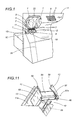
- the numeral 1 indicates a device for forming and transferring ordered stacks 2 of sheets, in particular bank notes 3 arriving from the outfeed of a machine 4 (only part of which is schematically illustrated in Figure 1) which checks the bank notes, rejecting any defective or damaged ones.
- the bank notes 3 are fed along a main feed pipe 5 and, once they reach one of the pipe 5 outfeeds 6, are picked up by rotary transfer drums 7 of the known type, each of which feeds a succession of bank notes 3 to an infeed zone 8 of one of the devices 1 fitted on the machine 4.
- Each device 1 in turn forms stacks 2 of bank notes 3 and feeds them to a banding machine, of the known type and therefore not illustrated.
- Each device 1 comprises a stack 2 forming channel 9, extending transversally to the pipe 5, from top to bottom, and located at a relative outfeed 6 of the bank note 3 feed pipe 5, downstream of the respective drum 7.
- each device 1 consists of a base 10, two side walls 11, 12 and a support surface 13 which extends parallel with the side wall 11 outside the forming channel 9.
- the forming channel 9 consists of two parts 14, 15, connected discontinuously and extending along a longitudinal axis 16.
- the two parts 14, 15 are at an angle to the vertical plane and are connected to one another by a curved connecting section 17.
- the first, upper part, labelled 14, is set at a downward angle rather than vertical, whilst the second, lower part, labelled 15, is substantially vertical.
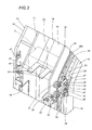
- the forming channel 9 comprises an accompanying element 18 which moves along the channel 9, driven by a flexible drive part 19 (for example a chain) looped around two wheels, respectively a driving wheel and a driven wheel, one of which, the lower driving wheel 20, is illustrated in Figure 2.
- the two wheels are located at the side of the channel 9 at opposite ends 9a, 9b of the channel 9, respectively upper and lower.
- the driving wheel 20 is driven by an electric motor 21 positioned close to the lower end 9b of the forming channel 9.
- the accompanying element 18 comprises a support surface 22 for the stack 2 of bank notes 3.
- the bank notes 3 are stacked on the support surface 22 according to a stacking axis 2a which is substantially perpendicular to the support surface 22.
- the surface 22 has tines 23 and the portion facing the side wall 12 has sliding means 24 which allow the accompanying element 18 to move along a guide 25, located on an outer surface of the side wall 12, defining a path 26 which is substantially parallel with the axis 16 of the forming channel 9.
- the sliding means 24 comprise a carriage 27 with a frame 28 which is rigidly fixed to the surface 22 and two rocker arms 29, 30, each fitted with two respective idle wheels 31, 32 and 33, 34 designed to engage with the sliding guide 25 on opposite sides of the guide 25.
- each arm 29, 30 pivots on the frame 28, at oscillation axes 35, 36 transversal to the channel 9 axis 16, using bearings which are not illustrated, so that they oscillate freely around the axes 35, 36.
- the distance between the oscillation axes 35 and 36 of the two arms 29 and 30 defines a carriage centre-to-centre distance 37, substantially parallel with the bank note 3 stacking axis 2a on the support surface 22.
- connection between the support surface 22 and the carriage 27 is made using rigid connecting parts 38, which slide through a longitudinal slot 39, visible in Figure 3, made in the side wall 12 and extending substantially parallel with the path 26 along the entire length of the forming channel 9.
- the straight lower part 15 of the forming channel 9 has two side guides 40 extending longitudinally to retain the bank notes 3 in the stack 2 during stack 2 downfeed towards the lower end 9b of the channel 9.
- the side guides 40 can be adjusted according to the length of the bank notes 3 calculated parallel with the base 10 of the channel 9, using actuators 41 of the known type.
- bars 42 which extend longitudinally substantially parallel with the axis 16, defining a part 43 which retains the bank notes 3 during their downfeed along the forming channel 9.
- the bars are supported by a plurality of crosspieces 44 which connect the retaining part 43 to the side walls 11, 12 of the forming channel 9.
- the upper end 9a of the forming channel 9 is fitted with a shielding device 45, a generic embodiment of which comprises a wall 46 which limits the entry of air flows from the pipe 5 into the channel 9.
- the air flows are used in the pipe to help feed the bank notes 3 to the relative drum 7 which, during rotation, produces further air flows which tend to pass along the forming channel 9.
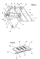
- the shielding wall 46 is mobile between a non-operating position in which the forming channel 9 infeed zone 8 is open, illustrated for example in Figure 2, and an operating position in which the infeed zone 8 is partially closed, illustrated for example in Figure 4.
- the wall 46 of the shielding device 45 consists of a door 47 which is rigidly connected, by brackets 48, to a shaft 49 extending along an axis 50.
- the shaft 49 is connected in such a way that it can rotate, to the base 10 of the channel 9 by means of supports 51 and one end 49a of the shaft is fitted with a crank 52 connected to a mobile rod 53 of an actuator 54 pivoted on a bracket 55 which is integral with the base 10 of the forming channel 9.
- the shielding wall 46 consists of a roller shutter 56 which slides on a roller 57 supported by the side walls 11, 12 and has an axis 57a which is transversal to the axis 16 of the channel 9.
- roller shutter 56 which open and close the infeed zone 8 are driven by an actuator 58, illustrated with a dashed line in the figure, and the lateral edges of the roller shutter engage with special sliding guides 59 in the side walls 11, 12 of the forming channel 9.
- the wall 46 consists of two wings respectively hinged on each of the side walls 11, 12 of the forming channel 9.
- the door 47 has a plurality of slots 60 extending transversally to the shaft 49. Inside each slot 60 there are vibrating elements 61, schematically illustrated in the figure and aiding correct bank note 3 stacking.
- a vibrating device 62 which, similarly to the vibrating elements 61 on the door 47, aids correct positioning and compacting of the bank notes 3 during the stack 2 forming stage.
- the vibrating device 62 comprises a source 63 of vibrations, located between the side wall 11 and the support surface 13, the source 63 being in contact, through an opening 64 in the side wall 11, with a rectangular plate 65.
- the plate 65 is connected to an inner surface 11a of the wall 11 facing the forming channel 9, is parallel with the wall 11 and is caused to vibrate by the source 63 with which it is in contact.
- the vibrating device 62 and the retaining part 43 together define positioning and compacting means 66 which cooperate with the side walls 11, 12 and the base 10.
- the opposite ends 40a, 40b of the guide 40 are connected to two cranks 67, which pivot at their first end 67a on pins 68 which are integral with a longitudinal box-shaped support and protection element 69, and at their second end 67b on brackets 70 which are integral with the guides 40.
- each crank 67 between the two ends 67a, 67b, has slots 71 in which pins 72 connecting two rods 73, 74 which extend longitudinally parallel with one another and with the guide 40 engage in such a way that they can slide.
- the rods 73, 74 are separated transversally, in such a way that the cranks 67 pivoted on the pins 68 can slide in the space between them.
- the tops of the rods 73, 74 are fixed to a single bracket 75, which is connected to the mobile rod 76 of an actuator 41 integral with the side wall 11, 12 of the forming channel 9.
- the accompanying element 18 moves along the channel 9 between two end operating positions, namely, a first position for receiving the bank notes 3 at the upper end 9a of the channel 9 and a second position for releasing the stack 2 at the lower end 9b of the channel 9.
- the accompanying element 18 is at the outfeed 6 of the feed pipe 5 and receives the bank notes 3 which are gradually laid on top of one another on the surface 22 to form a stack 2.
- the accompanying element 18 may, at least at its first, receiving position, perform a gradual downward movement depending on the number of bank notes 3 gradually released onto the surface 22.
- the gradual downward movement defines a series of intermediate positions for the accompanying element 18 as the stack 2 is formed, so that the last bank note 3 in the stack 2 is always at the same distance from the feed pipe 5 outfeed 6.
- the parts constituting the vibrating device 62 act upon the bank notes 3 stacked on the support surface 22 positioned close to the forming channel 9 infeed zone 8.
- the plate 65 is made to vibrate by the source of vibrations 63 illustrated with a dashed line in Figure 2 and transmits its vibrations to the bank notes 3 (not illustrated in Figure 11) which are gradually stacked, promoting correct stack 2 alignment.
- the mobile door 47 defines contrast means 77 co-operating with the mobile accompanying element 18 to compact the stack 2 of bank notes 3.
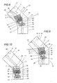
- Figures 6 and 7 clearly illustrate how, when travelling along the upper part 14 of the forming channel 9, the carriage 27 keeps the stack 2 with its stacking axis 2a substantially parallel with the axis 16 of the forming channel 9.
- the wheels 33, 34 of the arm 30 cover the curved section, whilst the wheels 31, 32 of the arm 29, which are upstream of the wheels 33, 34 with reference to the direction T of travel along the channel 9, are still running over a section of the guide 25 belonging to the upper, straight part 14 of the channel 9.
- the centre-to-centre distance 37 which coincides with the frame 28 axis assumes in succession a series of positions defining chords subtending the axis 16 in the curved section 17 of the channel 9.
- the presence of a given centre-to-centre distance 37 between the axes 35, 36 of the two arms 29, 30 which support the wheels 31, 32, 33, 34 and the location of the parts 38 which connect the support surface 22 to the carriage 27 in a substantially intermediate position relative to the centre-to-centre 37 mean that the variation in the bank note 3 stacking axis 2a performed in order to follow the axis 16 of the channel 9 takes longer than the time needed for the central portion of the carriage 27 to cover the curved section 17 of the channel 9.
- the arms 29, 30 assist the movement of the carriage 27, above all in the curved section, facilitating wheel 31, 32, 33, 34 engagement with the sliding guide 25.
- each side guide 40 constitutes the connecting rod of a four-bar linkage whose cranks are the cranks 67.
Landscapes
- Engineering & Computer Science (AREA)
- Mechanical Engineering (AREA)
- Pile Receivers (AREA)
- Vending Machines For Individual Products (AREA)
- Control Of Vending Devices And Auxiliary Devices For Vending Devices (AREA)
- Separation, Sorting, Adjustment, Or Bending Of Sheets To Be Conveyed (AREA)
Abstract
Description
- Figure 1 is a schematic perspective view, with some parts in cross-section and some parts cut away to better illustrate others, of a portion of a machine for arranging and checking bank notes, equipped with a device for forming and transferring ordered stacks of bank notes made in accordance with the present invention;
- Figure 2 is a schematic perspective view, with some parts cut away for greater clarity, of a part of the machine illustrated in Figure 1;
- Figure 3 is a schematic perspective view, with some parts cut away for greater clarity, of a detail from Figure 2;
- Figure 4 is a schematic perspective view of a detail from Figure 2;
- Figure 5 is a schematic perspective view of an alternative embodiment of a detail from Figure 2;
- Figures 6, 7, 8, 9 and 10 are schematic views of the detail shown in Figure 3 in a succession of operating stages;
- Figure 11 is a schematic perspective view of an alternative embodiment of the detail shown in Figure 4;
- Figure 12 is a schematic perspective view of a detail from Figure 2.
Claims (12)
- A device for forming and transferring ordered stacks (2) of bank notes (3) fed from a control machine, comprising a feed pipe (5) along which the bank notes (3) are fed in succession to the infeed (8) of at least one forming channel (9) comprising a base (10) and two side walls (11, 12) for retaining the bank notes (3) fed individually and in succession to the infeed (8) of the forming channel (9) by a rotary transfer part (7) located between the feed pipe (5) and the forming channel (9) and designed to place the bank notes (3) forming the stack (2) on top of one another, according to a stacking axis (2a), on an accompanying element (18), the latter being mobile along the forming channel (9), the device being characterised in that it comprises shielding means (45) at the infeed (8) of the forming channel (9).
- The device according to claim 1, characterised in that the shielding means (45) comprise at least one wall (46), being mobile between a non-operating position in which the infeed (8) of the forming channel (9) is open and an operating position in which the infeed (8) is partially closed.
- The device according to claim 2, characterised in that the mobile wall (46) defines contrast means (77) co-operating with the mobile accompanying element (18) to compact the stack (2) of bank notes (3).
- The device according to claim 2 or 3, characterised in that the mobile wall (46) comprises at least one door (47), oscillating about a shaft (49) positioned transversally to a longitudinal axis (16) of the forming channel (9).
- The device according to claim 4, characterised in that the mobile wall (46) comprises a door with two wings, each oscillating about a respective hinge; the hinges being attached to the two opposite side walls (11, 12) of the forming channel (9).
- The device according to claim 2 or 3, characterised in that the mobile wall (46) comprises a roller shutter (56), moving transversally to the forming channel (9) longitudinal axis (16), between two operating positions, one for opening and the other for partial closing of the forming channel (9).
- The device according to any of the claims from 1 to 6, characterised in that it comprises means (66) for positioning and compacting the stack (2) of bank notes (3), the means being located at the forming channel (9) infeed (8).
- The device according to claim 7, characterised in that the positioning and compacting means (66) comprise vibrating means (62) located at least on one of the three walls (10, 11, 12) of the forming channel (9).
- The device according to claim 8, characterised in that the vibrating means (62) comprise a plate (65) located at the forming channel (9) infeed and connected to a source (63) of vibrations.
- The device according to claim 1, in which the forming channel (9) comprises at least two parts (14, 15) which are substantially straight, being at different angles and connected to one another by a curved intermediate section (17), the device being characterised in that the accompanying element (18) is mobile along a guide (25) running parallel with the axis (16) of the forming channel (9) and comprises a support surface (22) for a stack (2) whose stacking axis (2a) is substantially perpendicular to the support surface (22), the support surface (22) being connected to means (24) which slide along the guide (25), said sliding means (24) comprising means (78) for adjusting the angle of the support surface (22) to the axis (16) of the forming channel (9).
- The device according to claim 10, characterised in that the sliding means (24) comprise a carriage (27) which moves along the guide (25) and the adjusting means (78) comprise two rocker arms (29, 30), each comprising two wheels (31, 32, 33, 34), each fitted at opposite ends of each of the rocker arms (29, 30) and being located on opposite sides of the guide (25), the rocker arms (29, 30) pivoting, in such a way that they can oscillate about relative pivoting axes (35, 36), on a frame element (28) of the carriage (27), the frame element (28) being connected to the support surface (22) and at least one of the two wheels (31, 32, 33, 34) of each rocker arm (29, 30) engaging temporarily in the guide (25).
- The device according to claim 11, characterised in that the pivoting axes (35, 36) of the rocker arms (29, 30) are separated by a given centre-to-centre distance (37), the rocker arms (29, 30) being designed to anticipate and delay angling of the axis (2a) of the stack (2) relative to the axis (16) of the forming channel (9) in the portions of the straight sections (14, 15) close to the curved connecting section (17) of the forming channel (9).
Applications Claiming Priority (2)
| Application Number | Priority Date | Filing Date | Title |
|---|---|---|---|
| IT2000BO000279A IT1321255B1 (en) | 2000-05-12 | 2000-05-12 | DEVICE FOR THE FORMATION AND TRANSFER OF ORDERED BANKNOTE BATTERIES. |
| ITBO200279 | 2000-05-12 |
Publications (2)
| Publication Number | Publication Date |
|---|---|
| EP1153870A2 true EP1153870A2 (en) | 2001-11-14 |
| EP1153870A3 EP1153870A3 (en) | 2002-10-30 |
Family
ID=11438473
Family Applications (1)
| Application Number | Title | Priority Date | Filing Date |
|---|---|---|---|
| EP01830301A Withdrawn EP1153870A3 (en) | 2000-05-12 | 2001-05-01 | A device for forming and transferring ordered stacks of bank notes |
Country Status (3)
| Country | Link |
|---|---|
| US (1) | US6543766B2 (en) |
| EP (1) | EP1153870A3 (en) |
| IT (1) | IT1321255B1 (en) |
Cited By (1)
| Publication number | Priority date | Publication date | Assignee | Title |
|---|---|---|---|---|
| EP1548661A3 (en) * | 2003-12-27 | 2006-02-08 | LG N-Sys. Inc. | Media dispensing unit |
Families Citing this family (7)
| Publication number | Priority date | Publication date | Assignee | Title |
|---|---|---|---|---|
| US7195236B2 (en) * | 2003-03-28 | 2007-03-27 | Northrop Grumman Corporation | Automated induction systems and methods for mail and/or other objects |
| US20050077217A1 (en) * | 2003-03-28 | 2005-04-14 | Hillerich Thomas A. | Carrier for mail and/or the like thin objects |
| JP2006528552A (en) * | 2003-05-13 | 2006-12-21 | ノースロップ グラマン コーポレイション | Improved object feeder pretreatment system |
| US20060099065A1 (en) * | 2004-08-27 | 2006-05-11 | Northrop Grumman Corporation | Preparation operator flex-station for carrier preparation |
| US7467792B2 (en) * | 2004-09-24 | 2008-12-23 | Northrop Grumman Corporation | Anti-toppling device for mail with retractable protrusion |
| JP5237386B2 (en) * | 2007-12-12 | 2013-07-17 | サンドビック インテレクチュアル プロパティー アクティエボラーグ | Shutter system |
| US7766171B2 (en) * | 2008-02-28 | 2010-08-03 | Northrop Grumman Systems Corporation | Rigid storage tray for flat and letter mail |
Family Cites Families (21)
| Publication number | Priority date | Publication date | Assignee | Title |
|---|---|---|---|---|
| US3441268A (en) * | 1967-06-01 | 1969-04-29 | Us Envelope Co | Device for tamping envelopes |
| DE2202334C3 (en) * | 1972-01-19 | 1981-09-17 | Tokyo Shibaura Electric Co., Ltd., Kawasaki, Kanagawa | Device for depositing thin, flexible sheets |
| JPS57138847U (en) * | 1981-02-24 | 1982-08-30 | ||
| JPS5864586A (en) * | 1981-10-15 | 1983-04-16 | ロ−レルバンクマシン株式会社 | Automatic teller |
| JPS5895069A (en) * | 1981-11-27 | 1983-06-06 | Toshiba Corp | Paper sheets recovery apparatus |
| JPS59205694A (en) | 1983-05-09 | 1984-11-21 | 株式会社東芝 | Sheet paper withdrawer |
| US4577853A (en) * | 1984-01-16 | 1986-03-25 | Harris Graphics Corporation | Stacking apparatus |
| JPS6216979A (en) * | 1985-07-16 | 1987-01-26 | Oki Electric Ind Co Ltd | Banknote stacking device |
| JPS62290670A (en) * | 1986-06-09 | 1987-12-17 | Toshiba Corp | Stacking device for paper sheets |
| CA1331027C (en) * | 1988-10-24 | 1994-07-26 | Robert A. Bryson, Sr. | Signature handling apparatus |
| US5112042A (en) * | 1990-03-30 | 1992-05-12 | Westinghouse Electric Corp. | Document transfer device for multiple pass document sorting machine |
| US5092575A (en) * | 1990-09-05 | 1992-03-03 | Pitney Bowes Inc. | Portable apparatus for supporting sheets |
| US5295674A (en) * | 1993-05-14 | 1994-03-22 | Xerox Corporation | High capacity envelope stacker apparatus |
| JPH0714049A (en) | 1993-06-28 | 1995-01-17 | Toshiba Corp | Paper storage device |
| JPH0776451A (en) * | 1993-09-09 | 1995-03-20 | Omron Corp | Alignment storage device for paper sheets |
| DE69535182T2 (en) * | 1994-05-20 | 2006-12-07 | Fujitsu Ltd., Kawasaki | Apparatus for processing paper sheets |
| US5871209A (en) * | 1996-03-01 | 1999-02-16 | Currency Systems International, Inc. | Cassette based document handling system |
| JPH09278262A (en) * | 1996-04-10 | 1997-10-28 | Omron Corp | Paper sheet stacking device and transaction processing device |
| IT1285719B1 (en) * | 1996-05-24 | 1998-06-18 | Gd Spa | DEVICE FOR THE TRAINING AND TRANSFER OF ORDERED STACKS OF SHEETS, IN PARTICULAR BANKNOTES |
| IT1292609B1 (en) * | 1997-06-09 | 1999-02-08 | Gd Spa | DEVICE AND METHOD FOR THE FORMATION OF ORDERED STACKS OF SHEETS OR GROUPS OF SHEETS, IN PARTICULAR BANKNOTES |
| IT1306257B1 (en) * | 1998-06-01 | 2001-06-04 | Gd Spa | DEVICE AND METHOD FOR THE FORMATION AND BANDING OF GROUPS SHEETS, IN PARTICULAR BANKNOTES. |
-
2000
- 2000-05-12 IT IT2000BO000279A patent/IT1321255B1/en active
-
2001
- 2001-05-01 EP EP01830301A patent/EP1153870A3/en not_active Withdrawn
- 2001-05-14 US US09/853,900 patent/US6543766B2/en not_active Expired - Fee Related
Cited By (2)
| Publication number | Priority date | Publication date | Assignee | Title |
|---|---|---|---|---|
| EP1548661A3 (en) * | 2003-12-27 | 2006-02-08 | LG N-Sys. Inc. | Media dispensing unit |
| US7464928B2 (en) | 2003-12-27 | 2008-12-16 | Lg N-Sys Inc. | Media discharging unit for media dispenser |
Also Published As
| Publication number | Publication date |
|---|---|
| EP1153870A3 (en) | 2002-10-30 |
| IT1321255B1 (en) | 2004-01-08 |
| US20020003330A1 (en) | 2002-01-10 |
| US6543766B2 (en) | 2003-04-08 |
| ITBO20000279A1 (en) | 2001-11-12 |
Similar Documents
| Publication | Publication Date | Title |
|---|---|---|
| US11787645B2 (en) | Conveyor device for conveying flexible containers along a packaging line | |
| JP4454968B2 (en) | Product packing method and machine using flat cylindrical parcel | |
| DK2193084T3 (en) | Device and method for filling a container | |
| EP2402270B1 (en) | Duplex-type product bag unloading apparatus | |
| US7591466B2 (en) | Device for transferring print products, conveyed while suspended from spaced-apart clamps on a circulating conveying element | |
| JPS60242163A (en) | Loader for signature, sheet and similar product proper to feeder for packaging machine, bookbinding machine, etc. | |
| WO2008032801A1 (en) | Conveyance device, and box packing device and box packing system with the same | |
| US6543766B2 (en) | Device for forming and transferring ordered stacks of bank notes | |
| JP4667633B2 (en) | Empty bag supply device and product bag take-out device in continuous transfer type bag filling and packaging machine | |
| JP2727281B2 (en) | Folding machine delivery device | |
| FI106015B (en) | Packing device and method of packing flat items such as books | |
| US6220427B1 (en) | Conveyor | |
| CN109850249A (en) | Equipment for transportation and packing | |
| JP5646872B2 (en) | Box conveying device in boxing equipment | |
| EP1584455B1 (en) | Machine for forming boxes | |
| US6973766B2 (en) | Device for packing flat articles in transport containers, particularly folded-flat folding boxes in casing cartons | |
| US4607473A (en) | Apparatus for handling flat, flexible web products | |
| US5921546A (en) | Apparatus for decelerating sheet material while maintaining sheet registration | |
| US8157263B2 (en) | Adjustable stacker infeed | |
| JP7409924B2 (en) | Bag feeding method and bag feeding device | |
| US6830242B2 (en) | Delivery device for removing folded printed products | |
| JP4149791B2 (en) | Method and apparatus for transporting packaging | |
| US8245611B2 (en) | Method and device for transporting flexible, two-dimensional products and simultaneously cutting these | |
| JP4990223B2 (en) | Attached document supply device | |
| US8485340B2 (en) | Device for transferring and nesting blister packs |
Legal Events
| Date | Code | Title | Description |
|---|---|---|---|
| PUAI | Public reference made under article 153(3) epc to a published international application that has entered the european phase |
Free format text: ORIGINAL CODE: 0009012 |
|
| AK | Designated contracting states |
Kind code of ref document: A2 Designated state(s): AT BE CH CY DE DK ES FI FR GB GR IE IT LI LU MC NL PT SE TR |
|
| AX | Request for extension of the european patent |
Free format text: AL;LT;LV;MK;RO;SI |
|
| RAP1 | Party data changed (applicant data changed or rights of an application transferred) |
Owner name: CURRENCY SYSTEMS INTERNATIONAL, INC. |
|
| PUAL | Search report despatched |
Free format text: ORIGINAL CODE: 0009013 |
|
| AK | Designated contracting states |
Kind code of ref document: A3 Designated state(s): AT BE CH CY DE DK ES FI FR GB GR IE IT LI LU MC NL PT SE TR |
|
| AX | Request for extension of the european patent |
Free format text: AL;LT;LV;MK;RO;SI |
|
| 17P | Request for examination filed |
Effective date: 20030113 |
|
| AKX | Designation fees paid |
Designated state(s): AT BE CH CY DE DK ES FI FR GB GR IE IT LI LU MC NL PT SE TR |
|
| 17Q | First examination report despatched |
Effective date: 20030401 |
|
| STAA | Information on the status of an ep patent application or granted ep patent |
Free format text: STATUS: THE APPLICATION IS DEEMED TO BE WITHDRAWN |
|
| 18D | Application deemed to be withdrawn |
Effective date: 20031201 |