EP1153687A1 - Target shape portion cutting apparatus, robot equiped with the apparatus and target shape portion cutting method - Google Patents
Target shape portion cutting apparatus, robot equiped with the apparatus and target shape portion cutting method Download PDFInfo
- Publication number
- EP1153687A1 EP1153687A1 EP01304210A EP01304210A EP1153687A1 EP 1153687 A1 EP1153687 A1 EP 1153687A1 EP 01304210 A EP01304210 A EP 01304210A EP 01304210 A EP01304210 A EP 01304210A EP 1153687 A1 EP1153687 A1 EP 1153687A1
- Authority
- EP
- European Patent Office
- Prior art keywords
- target shape
- shape portion
- metal sheet
- joint
- blade
- Prior art date
- Legal status (The legal status is an assumption and is not a legal conclusion. Google has not performed a legal analysis and makes no representation as to the accuracy of the status listed.)
- Granted
Links
- 238000005520 cutting process Methods 0.000 title claims description 84
- 238000000034 method Methods 0.000 title claims description 21
- 239000002184 metal Substances 0.000 claims abstract description 79
- 238000003825 pressing Methods 0.000 claims abstract description 20
- 238000010008 shearing Methods 0.000 claims abstract description 20
- 239000010953 base metal Substances 0.000 claims description 27
- 238000013459 approach Methods 0.000 claims description 5
- 239000000463 material Substances 0.000 claims description 3
- 239000007779 soft material Substances 0.000 claims description 3
- 238000005452 bending Methods 0.000 claims 1
- 238000003780 insertion Methods 0.000 description 11
- 230000037431 insertion Effects 0.000 description 11
- 210000000707 wrist Anatomy 0.000 description 11
- 238000010586 diagram Methods 0.000 description 7
- 238000012805 post-processing Methods 0.000 description 4
- 238000012937 correction Methods 0.000 description 3
- 238000000926 separation method Methods 0.000 description 3
- 238000001179 sorption measurement Methods 0.000 description 2
- 229910000831 Steel Inorganic materials 0.000 description 1
- ZPUCINDJVBIVPJ-LJISPDSOSA-N cocaine Chemical compound O([C@H]1C[C@@H]2CC[C@@H](N2C)[C@H]1C(=O)OC)C(=O)C1=CC=CC=C1 ZPUCINDJVBIVPJ-LJISPDSOSA-N 0.000 description 1
- 230000000694 effects Effects 0.000 description 1
- 239000004033 plastic Substances 0.000 description 1
- 238000012545 processing Methods 0.000 description 1
- 239000010959 steel Substances 0.000 description 1
Images






Classifications
-
- B—PERFORMING OPERATIONS; TRANSPORTING
- B23—MACHINE TOOLS; METAL-WORKING NOT OTHERWISE PROVIDED FOR
- B23D—PLANING; SLOTTING; SHEARING; BROACHING; SAWING; FILING; SCRAPING; LIKE OPERATIONS FOR WORKING METAL BY REMOVING MATERIAL, NOT OTHERWISE PROVIDED FOR
- B23D31/00—Shearing machines or shearing devices covered by none or more than one of the groups B23D15/00 - B23D29/00; Combinations of shearing machines
-
- B—PERFORMING OPERATIONS; TRANSPORTING
- B23—MACHINE TOOLS; METAL-WORKING NOT OTHERWISE PROVIDED FOR
- B23D—PLANING; SLOTTING; SHEARING; BROACHING; SAWING; FILING; SCRAPING; LIKE OPERATIONS FOR WORKING METAL BY REMOVING MATERIAL, NOT OTHERWISE PROVIDED FOR
- B23D15/00—Shearing machines or shearing devices cutting by blades which move parallel to themselves
-
- Y—GENERAL TAGGING OF NEW TECHNOLOGICAL DEVELOPMENTS; GENERAL TAGGING OF CROSS-SECTIONAL TECHNOLOGIES SPANNING OVER SEVERAL SECTIONS OF THE IPC; TECHNICAL SUBJECTS COVERED BY FORMER USPC CROSS-REFERENCE ART COLLECTIONS [XRACs] AND DIGESTS
- Y10—TECHNICAL SUBJECTS COVERED BY FORMER USPC
- Y10S—TECHNICAL SUBJECTS COVERED BY FORMER USPC CROSS-REFERENCE ART COLLECTIONS [XRACs] AND DIGESTS
- Y10S83/00—Cutting
- Y10S83/928—Vehicle-mounted tool
-
- Y—GENERAL TAGGING OF NEW TECHNOLOGICAL DEVELOPMENTS; GENERAL TAGGING OF CROSS-SECTIONAL TECHNOLOGIES SPANNING OVER SEVERAL SECTIONS OF THE IPC; TECHNICAL SUBJECTS COVERED BY FORMER USPC CROSS-REFERENCE ART COLLECTIONS [XRACs] AND DIGESTS
- Y10—TECHNICAL SUBJECTS COVERED BY FORMER USPC
- Y10T—TECHNICAL SUBJECTS COVERED BY FORMER US CLASSIFICATION
- Y10T83/00—Cutting
- Y10T83/04—Processes
-
- Y—GENERAL TAGGING OF NEW TECHNOLOGICAL DEVELOPMENTS; GENERAL TAGGING OF CROSS-SECTIONAL TECHNOLOGIES SPANNING OVER SEVERAL SECTIONS OF THE IPC; TECHNICAL SUBJECTS COVERED BY FORMER USPC CROSS-REFERENCE ART COLLECTIONS [XRACs] AND DIGESTS
- Y10—TECHNICAL SUBJECTS COVERED BY FORMER USPC
- Y10T—TECHNICAL SUBJECTS COVERED BY FORMER US CLASSIFICATION
- Y10T83/00—Cutting
- Y10T83/04—Processes
- Y10T83/0605—Cut advances across work surface
-
- Y—GENERAL TAGGING OF NEW TECHNOLOGICAL DEVELOPMENTS; GENERAL TAGGING OF CROSS-SECTIONAL TECHNOLOGIES SPANNING OVER SEVERAL SECTIONS OF THE IPC; TECHNICAL SUBJECTS COVERED BY FORMER USPC CROSS-REFERENCE ART COLLECTIONS [XRACs] AND DIGESTS
- Y10—TECHNICAL SUBJECTS COVERED BY FORMER USPC
- Y10T—TECHNICAL SUBJECTS COVERED BY FORMER US CLASSIFICATION
- Y10T83/00—Cutting
- Y10T83/869—Means to drive or to guide tool
- Y10T83/875—With templet surface following tool
-
- Y—GENERAL TAGGING OF NEW TECHNOLOGICAL DEVELOPMENTS; GENERAL TAGGING OF CROSS-SECTIONAL TECHNOLOGIES SPANNING OVER SEVERAL SECTIONS OF THE IPC; TECHNICAL SUBJECTS COVERED BY FORMER USPC CROSS-REFERENCE ART COLLECTIONS [XRACs] AND DIGESTS
- Y10—TECHNICAL SUBJECTS COVERED BY FORMER USPC
- Y10T—TECHNICAL SUBJECTS COVERED BY FORMER US CLASSIFICATION
- Y10T83/00—Cutting
- Y10T83/929—Tool or tool with support
- Y10T83/9411—Cutting couple type
- Y10T83/9447—Shear type
Definitions
- This invention relates to a shape portion cutting apparatus and method of cutting out a predermined shape portion from the remainder of a metal sheet, and a robot equipped with the shape portion cutting apparatus.
- the metal sheet is first worked so that the target shaped portion, a portion surrounding the target shape portion (the surrounding portion being hereinafter called “base metal sheet”) and possibly at least one elongated connecting or joint portion for joining the former two portions are formed on the metal sheet, and then the joint portion is cut off, using:
- method (b) likewise causes unstable position and posture of the target shape portion after it is cut out. Therefore, like method (a), method (b) makes it difficult for the robot to hold and take away the cut-out target shape portion. This makes it difficult to achieve automation of working metal sheets, remote manipulation of the robot and so forth.
- the above method (c) cuts out the joint portion formed on the metal sheet by the tool, such as a nipper, a hole large enough for allowing the free end of the tool to enter has to be formed in an area around the joint portion of the metal sheet. Further, since the tool (nipper) moves in the widthwise direction of the joint portion to cut out the joint portion, a part of the joint portion remains on the cut-out target shape portion. Therefore this method requires post-processing for removing the remaining portion of the joint portion. Further, total separation of the target shape portion cannot be confirmed based on only the tool movement.
- the tool may cut the member which supports the metal sheet.
- An object of the present invention is to provide a target shape portion cutting apparatus and method that are designed in such a manner that when a target shape portion formed on a metal sheet is cut out from the remaining portion of the metal sheet, the results of the separation require no post-processing and do not interrupt taking out of a cut-out target shape portion.
- a target shape portion cutting apparatus which comprises a first member having a first blade for pressing against a boundary portion between the target shape portion and the joint portions of the perforated metal sheet from one face of the perforated metal sheet and from the side of the target shape portion; and a second member having a second blade which approaches the joint portion from the other face of the perforated metal sheet, grips the boundary portion in association with the first blade in a thickness direction of the perforated metal sheet and shears the perforated metal sheet at the boundary portion to thereby cut the target shape portion off a joint portion.
- the second member having the second blade is supported in a manner such that it rotates relative to the first member having the first blade and is driven by a cylinder or a motor.
- the second member having the second blade is moved by a cylinder or a motor in the thickness direction of the perforated metal sheet relative to the first member having the first blade and cuts the target shape portion off a joint portion.
- the second member having the second blade is thick enough to be able to bend a joint portion by pushing it at the time of cutting out the target shape portion from the joint portion.
- a robot may mount the target shape portion cutting apparatus to cut a target shape portion of a metal sheet off a joint portion which connects the target shape portion to a base metal sheet.
- a method of cutting out a target shape portion from a base metal sheet using the robot comprises a step of placing a metal sheet having the target shape portion connected to the base metal sheet with one or a plurality of joint portions on a mounting section whose surface member is made of a soft material or a brush-like material soft enough to be able to keep a plane posture of the target shape portion and the base metal sheet; a step of pressing an exposed region of the mounting section with the second member having the second blade through a tool insertion hole formed adjacent to the target shape portion to be cut out; a step of moving the second blade under the joint portion to be cut out from the target shape portion while pressing the mounting section with the second member having the second blade; a step of pressing a boundary portion between the target shape portion and the joint portion with the first blade positioned above the joint portion, from the side of the target shape portion; and a step of moving the second blade upward to snip off the joint portion in association with the first blade.
- a target shape portion cutting apparatus according to a first embodiment of the present invention will now be described with reference to Figs. 1 through 9.
- Fig. 1 exemplifies a robot 2 equipped with a target shape portion cutting apparatus 1 according to the embodiment.
- the robot 2 comprises a rotary body 4 which rotates around the vertical axis with respect to a base 3, a first arm 5 mounted on the rotary body 4, a second arm 6 attached to the distal end of the first arm 5, and a wrist 7 connected to the distal end of the second arm 6.
- the first arm 5 turns around the horizontal axis.
- the second arm 6 likewise turns around the horizontal axis.
- the wrist 7 rotates around three axes perpendicular to one another.
- the target shape portion cutting apparatus 1 is attached to the wrist 7 of the robot 2 via an automatic tool changer 8.
- the automatic tool changer 8 has a robot-side mounting member 8a to be attached to the flange surface of the wrist 7 and a tool-side mounting member 8b to be attached to the tool side (i.e., to the target shape portion cutting apparatus 1 in the embodiment).
- Various tools including the target shape portion cutting apparatus 1 may be attached to or detached from the wrist 7 of the robot 2 by connecting or disconnecting the robot-side mounting member 8a and the tool-side mounting member 8b of the automatic tool changer 8 to or from the flange surface of the wrist 7 and the tool attached to the wrist 7.
- Fig. 2A is a side view of the target shape portion cutting apparatus 1
- Fig. 2B is a partial front view for explaining how to cut a joint portion between a target shape portion and a base metal sheet with the target shape portion cutting apparatus 1 in Fig. 2A.
- the target shape portion cutting apparatus 1 has an attachment member 10 and a tool frame 11 secured to the attachment member 10.
- the attachment member 10 is used to attach the target shape portion cutting apparatus 1 to the automatic tool changer 8 shown in Fig. 1.
- a fixed blade member 21 having a first blade 21a (fixed cutting blade) is secured to the lower end of the tool frame 11.
- a pressing block 16 (Fig. 2B) which presses a target shape portion formed on a metal sheet from above is fixed to a side of the tool frame 11 opposite the side where the fixed blade member 21 is secured.
- a movable blade member 22 having a second blade 22a (movable cutting blade) at one end thereof is rotatably attached to a pin 25 which protrudes from the side surface of the toot frame 11. As the second blade 22a rotates with respect to the first blade 21a, a joint portion which connects the target shape portion to the base metal sheet is cut to separate the target shape portion from the base metal sheet.
- the first blade 21a and the second blade 22a which are both super steel chips available on the market, are respectively mounted on the fixed blade member 21 and the movable blade member 22 in a replaceable manner.
- the movable blade member 22 is thick enough to be able to bend a portion near the cut surface of a joint portion when its second blade 22a turns and cuts the joint portion in association with the first blade 21a.
- a drive cylinder 12 is attached to the tool frame 11.
- the drive cylinder 12 uses air pressure, hydraulic pressure or a drive source such as a motor or a servo motor.
- a pin 23 provided at the distal end of a rod 13 of the drive cylinder 12 is engaged with an elongated hole 24 formed in an end portion of the movable blade member 22 opposite the end where the second blade 22a is attached. Since the drive cylinder 12 is actuated, therefore, the movable blade member 22 rotates around the pin 25 so that the second blade 22a is closed with respect to the first blade 21a, thereby cutting a joint portion between the target shape portion and the base metal sheet, as will be discussed later.
- a dog 14 is attached to the rod 13 of the drive cylinder 12.
- a pair of proximity switches 15a and 15b are attached to the tool frame 11 at positions above and below the dog 14.
- the dog 14 contacts the lower proximity switch 15b, indicating that the second blade 22a is closed with respect to the first blade 21a.
- the dog 14 contacts the upper proximity switch 15a, indicating that the second blade 22a is open with respect to the first blade 21a.
- a metal sheet 30 having a joint portion which is to be cut by the opening/closing action of the second blade 22a with respect to the first blade 21a is placed on a mounting section 27 as shown in Fig. 2A.
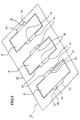
- holes 34 are formed in right and left sides of each joint portion 33 between the target shape portion 31 and the base metal sheet 32 of a metal sheet 30.
- This holes 34 has a predetermined width and a predetermined length where the movable blade member 22 is inserted.
- one target shape portion 31 is connected to the base metal sheet 32 with two joint portions 33.
- Reference numeral 35 denotes a boundary line between the target shape portion 31 and each joint portion 33.
- the joint portion 33 is cut along the boundary line 35 by the rotation of the second blade 22a with respect to the first blade 21a, as will be discussed later.
- Fig. 4 illustrates procedures of cutting the joint portion 33 between the target shape portion 31 and the base metal sheet 32 in the metal sheet 30.
- a metal sheet is worked into a shape as shown in Fig. 3 and the worked metal sheet 30 is picked up and taken out by the robot 2 and securely placed on the mounting section 27 of a work table (steps 100 and 101).
- the mounting section 27 is made of a material, such as a brush and sponge rubber, soft enough to be able to keep a plane posture of the metal sheet 30 as shown in Fig. 2A.
- the metal sheet 30 placed on the mounting section 27 is photographed with a camera (not shown) and the image is subjected to image processing in an image processor (not shown) to acquire the amount of positional deviation from the reference position of the metal sheet 30. Based on the amount of positional deviation, position correction data is acquired.
- a robot control apparatus receives the position correction data from the image processor (step 102). The robot control apparatus then obtains the shearing position (the boundary line 35 between the target shape portion 31 and the joint portion 33) based on the received position correction data to generate robot manipulation data (step 103).
- a tool for holding the metal sheet 30 is detached from the wrist 7 of the robot 2 using the automatic tool changer 8 and the target shape portion cutting apparatus 1 is attached to the wrist 7 as shown in Fig. 1.
- the target shape portion cutting apparatus 1 shears the joint portion 33 and cuts out the target shape portion 31 from the base metal sheet 32 (step 104). The details of the cutting operation will be given later.
- the target shape portion cutting apparatus 1 is detached from the wrist 7 of the robot 2 and a tool for grasping the target shape portion 31 is attached to the wrist 7. Then, the tool holds the target shape portion 31 and takes the target shape portion out for placement at a predetermined position in a predetermined posture (step 105).
- the above explanation is of the outline of the procedures for cutting out the target shape portion 31 from the worked metal sheet 30 and taking out the target shape portion 31.
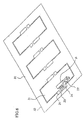
- Fig. 5 shows the state where the distal end of the movable blade member 22 of the target shape portion cutting apparatus 1 just starts entering the tool insertion hole 34 of the worked metal sheet 30.
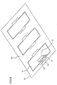
- Fig. 6 shows the state where the distal end of the movable blade member 22 is inserted into the tool insertion hole 34 while being open with respect to the fixed blade member 21.
- the state where the movable blade member 22 is open with respect to the fixed blade member 21 can be detected by the dog 14 and the proximity switch 15a.
- the worked metal sheet 30 is securely placed on the top surface of the mounting section 27 made of a soft material such as brush or sponge rubber. This allows the second blade 22a of the movable blade member 22 to pass through the tool insertion hole 34 of the metal sheet 30 and go further down below the bottom surface of the joint portion 33 while deforming the brush, sponge rubber or the like of the mounting section 27.
- the target shape portion cutting apparatus 1 whose movable blade member 22 is positioned in the tool insertion hole 34 as shown in Fig. 6 is moved in the widthwise direction of the metal sheet 30 toward the joint portion 33. During the movement of the target shape portion cutting apparatus 1, the movable blade member 22 slides on the mounting section 27.
- the movement of the target shape portion cutting apparatus 1 causes one side of the movable blade member 22 to closely contact the side edge of the target shape portion 31.
- the target shape portion cutting apparatus 1 presses the fixed blade member 21 and the pressing block 16 against the top surface of the target shape portion 31 so that the edge line of the first blade 21a of the fixed blade member 21 comes over the boundary line 35.
- Fig. 7 shows the state in which the positioning is completed.
- the drive cylinder 12 of the target shape portion cutting apparatus 1 is driven to turn the movable blade member 22 at the position and in the posture shown in Fig. 7 around the pin 25 to engage the first blade 21a of the fixed blade member 21 with the second blade 22a of the movable blade member 22 and shear the joint portion 33 at the boundary line 35 between the joint portion 33 and the target shape portion 31, as shown in Fig. 8.
- the target shape portion 31 is pressed by the fixed blade member 21 and the pressing block 16 while shearing the joint portion 33, the target shape portion 31 is not moved by this shearing operation (or by the rotation of the movable blade member 22).
- the rotation of the movable blade member 22 up to the last position or the complete engagement of the first blade 21a with the second blade 22a is detected and checked by the proximity switch 15b.
- the movable blade member 22 rotates further upward and passes through a clearance between the end face of the cut joint portion 33 and the side end face of the target shape portion 31. Since the movable blade member 22 has a predetermined thickness (greater than the clearance) as mentioned above, however, the movable blade member 22 interferes with the joint portion 33 and bends the sheared-side end of the joint portion 33 upward as the movable blade member passes through the clearance.
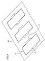
- the joint portion 33 remaining on the side of the base metal sheet 32 is kept curved as shown in Fig. 9. Therefore, when picking up the target shape portion 31 in Fig. 9 to take out the target shape portion from the worked metal sheet 30, the target shape portion 31 does not interfere with the sheared-side end of the joint portion 33.
- the second blade 22a of the movable blade member 22 moves in the direction of the thickness of the sheet relative to the first blade 21a of the fixed blade member 21 and cuts the joint portion 33 at the boundary line 35 between the joint portion 33 and the target shape portion 31, so that burrs does not occur on the sheared surface on the side of the target shape portion 31.
- the target shape portion 31 does not contact the sheared joint portion 33. Further, during shearing of the joint portion 33, the position and posture of the target shape portion 31 do not change.
- the movable blade member 22 passes through the tool insertion hole 34 to deform the brush, sponge rubber or the like that constitutes the mounting section 27 on which the metal sheet 30 is placed, the brush, sponge rubber or the like is not cut with the forward movement and the rotation of the movable blade member 22.
- the work of cutting out a target shape portion is carried out by a single robot to which tools, such a hand for holding the metal sheet 30 and the target shape portion 31 and the target shape portion cutting apparatus 1, are attached for the work.
- a plurality of robots may be used to individually perform the work of holding and carrying the metal sheet 30 and the target shape portion 31 and the work of cutting out the target shape portion 31.
- an adsorption pad may be used to adsorb and press the target shape portion 31 of the metal sheet 30, so that, after shearing of the joint portion 33, the target shape portion 31 adsorbed by the adsorption pad is taken out and conveyed to a predetermined position.
- a target shape portion cutting apparatus 1' according to the second embodiment of the present invention will be discussed below with reference to Figs. 10A, 10B and 11.
- the second blade or the movable blade moves (up and down) while maintaining its posture with respect to the first blade or the fixed blade, so that the joint portion 33 between the target shape portion 31 and the base metal sheet 32 in the worked metal sheet is sheared.
- the target shape portion cutting apparatus 1' has an attachment member 40 and a tool frame 41 secured to the attachment member 40.
- the attachment member 40 is used to attach the target shape portion cutting apparatus 1' to the automatic tool changer 8 shown in Fig. 1.
- a drive cylinder 42 is attached to the tool frame 41.
- a fixed blade member 46 is attached to the lower end of the tool frame 41.
- a movable blade member 47 is attached to a rod 43 of the drive cylinder 42 via a link member 44.
- a first blade 46a as a fixed blade is attached to the fixed blade member 46, and a second blade 47a as a movable blade is attached to the movable blade member 47.
- Fig. 10A shows the state where the rod 43 of the drive cylinder 42 moves downward so that the movable blade member 47 (second blade 47a) is open with respect to the fixed blade member 46 (first blade 46a).
- Fig. 11 shows the state where the movable blade member 47 (second blade 47a) is closed (engaged) with respect to the fixed blade member 46 (first blade 46a).
- a pressing block 48 which presses a target shape portion formed on a metal sheet from above is secured to the side of the tool frame 41 opposite the side where the fixed blade member 46 is securely attached.
- the target shape portion cutting apparatus 1' is attached to the robot 2. With the second blade 47a set open with respect to the first blade 46a as shown in Fig. 10, the distal end of the movable blade member 47 is inserted in to the tool insertion hole 34 of the worked metal sheet 30.
- the target shape portion cutting apparatus 1' is moved forward to the position where the first blade 46a and the second blade 47a sandwich the joint portion 33 from above and below.
- One side face of the movable blade member 47 is positioned in close contact with the associated side end face of the target shape portion 31 in the metal sheet 30.
- the fixed blade member 46 and the pressing block 48 are pressed against the top surface of the target shape portion 31 in such a way that the edge line of the first blade 46a of the fixed blade member 46 comes over the boundary line 35 between the joint portion 33 and the target shape portion 31.
- the drive cylinder 42 is actuated to lift the movable blade member 47 above with respect to the fixed blade member 46 as shown in Fig. 11, so that the joint portion 33 is sheared at the boundary line 35 by the cooperation of the first blade 46a and the second blade 47a.
- the target shape portion 31 when picking up and taking out the target shape portion 31 after shearing the joint portion 33, the target shape portion 31 does not interfere with the sheared joint portion 33. This facilitates the taking out operation of the target shape portion 31.
- the target shape portion 31 is kept pressed by the fixed blade member 46 and the pressing block 48, thus preventing the target shape portion 31 from being moved by the shearing operation (the up and down movement of the movable blade member 47).
- the movable blade member 47 passes through the tool insertion hole 34 to deform the brush, sponge rubber or the like that constitutes the mounting section 27 on which the metal sheet 30 is placed, the sponge rubber or the brush is not cut with the forward movement and the rotation of the movable blade member 47, in the same way as in the case of the first embodiment.
- burr does not cause so that no post-processing is required.
- the cut end face of the joint portion does not contact or interfere with the end face of the target shape portion after shearing of the joint portion, it is easy to take out the cut-out target shape portion. This facilitates the automation of the robot-based metal sheet working. Further, as the mounting section on which the metal sheet is placed is not cut by the shearing of the joint portion, longer service life of the mounting section can be expected. Further, as the target shape portion, even when it has bee cut out, staying on the mounting section without dropping below, it becomes easier to collect and align individual target shape portions. In addition, it is easy to automatically collect and align individual base metal sheets from which target shape portions have been cut out.
Landscapes
- Engineering & Computer Science (AREA)
- Mechanical Engineering (AREA)
- Manipulator (AREA)
- Punching Or Piercing (AREA)
- Shearing Machines (AREA)
- Perforating, Stamping-Out Or Severing By Means Other Than Cutting (AREA)
Abstract
Description
- This invention relates to a shape portion cutting apparatus and method of cutting out a predermined shape portion from the remainder of a metal sheet, and a robot equipped with the shape portion cutting apparatus.
- For cutting out a predetermined or target shape portion from a metal sheet, the metal sheet is first worked so that the target shaped portion, a portion surrounding the target shape portion (the surrounding portion being hereinafter called "base metal sheet") and possibly at least one elongated connecting or joint portion for joining the former two portions are formed on the metal sheet, and then the joint portion is cut off, using:
- (a) a method of mechanically applying an impact or vibration to a portion near the joint portion to thereby cause plastic deformation so that a link portion between the target shape portion and the base metal sheet is cut out;
- (b) a method of cutting out the target shape portion by a finishing machine without leaving any joint portion, and dropping the target shape portion on a conveyor or the like for collection of the target shape portion; or
- (c) a method of using a robot mounting a target shape portion cutting apparatus equipped with a scissors-like tool (nipper), which causes the tool to approach vertically to a joint portion between the target shape portion and the base metal sheet, from above, so that the blade of the tool abuts the top surface of the joint portion to thereby snip off the joint portion in the plane direction.
-
- Since the above method (a) applies an impact or vibration to the joint portion, burrs are produced on the portion where the target shape portion has been cut out. Therefore, post processing, such as burr removal, is needed after separating the target shape portion. Further, since the position and posture of the target shape portion after separation are not stable, it is difficult for the robot to hold and take away the cut-out target shape portion. This makes it difficult to achieve automation of working metal sheets, remote manipulation of the robot and so forth.
- The above method (b) likewise causes unstable position and posture of the target shape portion after it is cut out. Therefore, like method (a), method (b) makes it difficult for the robot to hold and take away the cut-out target shape portion. This makes it difficult to achieve automation of working metal sheets, remote manipulation of the robot and so forth.
- Since the above method (c) cuts out the joint portion formed on the metal sheet by the tool, such as a nipper, a hole large enough for allowing the free end of the tool to enter has to be formed in an area around the joint portion of the metal sheet. Further, since the tool (nipper) moves in the widthwise direction of the joint portion to cut out the joint portion, a part of the joint portion remains on the cut-out target shape portion. Therefore this method requires post-processing for removing the remaining portion of the joint portion. Further, total separation of the target shape portion cannot be confirmed based on only the tool movement. Moreover, it is difficult to take out a cut-out target portion because a portion of the joint portion remaining on the target shape portion may interfere with a portion of the joint portion remaining on the base metal sheet when cutting out and taking out the target shape portion. In addition, as the free end of the tool goes through a tool insertion hole formed in the metal sheet and protrudes further below the bottom surface of the metal sheet when the target shape portion is cut out, the tool may cut the member which supports the metal sheet.
- An object of the present invention is to provide a target shape portion cutting apparatus and method that are designed in such a manner that when a target shape portion formed on a metal sheet is cut out from the remaining portion of the metal sheet, the results of the separation require no post-processing and do not interrupt taking out of a cut-out target shape portion.
- To achieve the abovementioned object with a metal sheet which has been worked in such a way that a target shape is connected to a base metal through one or a plurality of joint portions by forming a hole at a region adjacent to the joint portion, a target shape portion cutting apparatus according to one aspect of the present invention is employed which comprises a first member having a first blade for pressing against a boundary portion between the target shape portion and the joint portions of the perforated metal sheet from one face of the perforated metal sheet and from the side of the target shape portion; and a second member having a second blade which approaches the joint portion from the other face of the perforated metal sheet, grips the boundary portion in association with the first blade in a thickness direction of the perforated metal sheet and shears the perforated metal sheet at the boundary portion to thereby cut the target shape portion off a joint portion.
- The second member having the second blade is supported in a manner such that it rotates relative to the first member having the first blade and is driven by a cylinder or a motor. Alternatively, the second member having the second blade is moved by a cylinder or a motor in the thickness direction of the perforated metal sheet relative to the first member having the first blade and cuts the target shape portion off a joint portion. The second member having the second blade is thick enough to be able to bend a joint portion by pushing it at the time of cutting out the target shape portion from the joint portion.
- A robot may mount the target shape portion cutting apparatus to cut a target shape portion of a metal sheet off a joint portion which connects the target shape portion to a base metal sheet.
- A method of cutting out a target shape portion from a base metal sheet using the robot comprises a step of placing a metal sheet having the target shape portion connected to the base metal sheet with one or a plurality of joint portions on a mounting section whose surface member is made of a soft material or a brush-like material soft enough to be able to keep a plane posture of the target shape portion and the base metal sheet; a step of pressing an exposed region of the mounting section with the second member having the second blade through a tool insertion hole formed adjacent to the target shape portion to be cut out; a step of moving the second blade under the joint portion to be cut out from the target shape portion while pressing the mounting section with the second member having the second blade; a step of pressing a boundary portion between the target shape portion and the joint portion with the first blade positioned above the joint portion, from the side of the target shape portion; and a step of moving the second blade upward to snip off the joint portion in association with the first blade.
- For a better understanding of the invention, and to show how the same may be carried into effect, reference will now be made, by way of example, to the accompanying drawings, in which:-
- Fig. 1 is a perspective view of a robot mounting a target shape portion cutting apparatus according to a first embodiment of the present invention;
- Fig. 2A is a side view of the target shape portion cutting apparatus in Fig. 1;
- Fig. 2B is a partly enlarged view (front view) of the target shape portion cutting apparatus in Fig. 2A;
- Fig. 3 is a diagram showing an example of a worked metal sheet in which a target shape portion which has been formed is connected to a base metal sheet via joint portions;
- Fig. 4 is a diagram for explaining procedures of cutting out a target shape portion;
- Fig. 5 is a diagram for explaining an operation of cutting out a target shape portion from the worked metal sheet shown in Fig. 3, in which a movable blade member of the target shape portion cutting apparatus is in a postion in which it is just about to start entering a tool insertion hole formed in the metal sheet;
- Fig. 6 is a diagram showing the movable blade member inserted in the tool insertion hole from the position in Fig. 5;
- Fig. 7 is a diagram showing the movable blade member positioned ready to cut out a joint portion after moving from the position in Fig. 6 toward the joint portion;
- Fig. 8 is a diagram showing the movable blade member which has just sheared the joint portion after pivoting from the position shown in Fig. 7;
- Fig. 9 is a diagram depicting the worked metal sheet with the joint portion sheared;
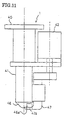
- Fig. 10A is a side view of a target shape portion cutting apparatus according to a second embodiment of the present invention in which a second blade is open with respect to a first blade;
- Fig. 10B is a partly enlarged view (front view) of the target shape portion cutting apparatus in Fig. 10A; and
- Fig. 11 is a side view of the target shape portion cutting apparatus in Figs. 10A in which the second blade is closed with respect to the first blade.
-
- A target shape portion cutting apparatus according to a first embodiment of the present invention will now be described with reference to Figs. 1 through 9.
- Fig. 1 exemplifies a
robot 2 equipped with a target shapeportion cutting apparatus 1 according to the embodiment. Therobot 2 comprises a rotary body 4 which rotates around the vertical axis with respect to abase 3, afirst arm 5 mounted on the rotary body 4, a second arm 6 attached to the distal end of thefirst arm 5, and a wrist 7 connected to the distal end of the second arm 6. Thefirst arm 5 turns around the horizontal axis. The second arm 6 likewise turns around the horizontal axis. The wrist 7 rotates around three axes perpendicular to one another. - The target shape
portion cutting apparatus 1 is attached to the wrist 7 of therobot 2 via an automatic tool changer 8. The automatic tool changer 8 has a robot-side mounting member 8a to be attached to the flange surface of the wrist 7 and a tool-side mounting member 8b to be attached to the tool side (i.e., to the target shapeportion cutting apparatus 1 in the embodiment). Various tools including the target shapeportion cutting apparatus 1 may be attached to or detached from the wrist 7 of therobot 2 by connecting or disconnecting the robot-side mounting member 8a and the tool-side mounting member 8b of the automatic tool changer 8 to or from the flange surface of the wrist 7 and the tool attached to the wrist 7. - Fig. 2A is a side view of the target shape
portion cutting apparatus 1, and Fig. 2B is a partial front view for explaining how to cut a joint portion between a target shape portion and a base metal sheet with the target shapeportion cutting apparatus 1 in Fig. 2A. - The target shape
portion cutting apparatus 1 has anattachment member 10 and atool frame 11 secured to theattachment member 10. Theattachment member 10 is used to attach the target shapeportion cutting apparatus 1 to the automatic tool changer 8 shown in Fig. 1. Afixed blade member 21 having afirst blade 21a (fixed cutting blade) is secured to the lower end of thetool frame 11. A pressing block 16 (Fig. 2B) which presses a target shape portion formed on a metal sheet from above is fixed to a side of thetool frame 11 opposite the side where thefixed blade member 21 is secured. - A
movable blade member 22 having asecond blade 22a (movable cutting blade) at one end thereof is rotatably attached to apin 25 which protrudes from the side surface of thetoot frame 11. As thesecond blade 22a rotates with respect to thefirst blade 21a, a joint portion which connects the target shape portion to the base metal sheet is cut to separate the target shape portion from the base metal sheet. - The
first blade 21a and thesecond blade 22a, which are both super steel chips available on the market, are respectively mounted on the fixedblade member 21 and themovable blade member 22 in a replaceable manner. As will be discussed later, themovable blade member 22 is thick enough to be able to bend a portion near the cut surface of a joint portion when itssecond blade 22a turns and cuts the joint portion in association with thefirst blade 21a. - A
drive cylinder 12 is attached to thetool frame 11. Thedrive cylinder 12 uses air pressure, hydraulic pressure or a drive source such as a motor or a servo motor. Apin 23 provided at the distal end of arod 13 of thedrive cylinder 12 is engaged with anelongated hole 24 formed in an end portion of themovable blade member 22 opposite the end where thesecond blade 22a is attached. Since thedrive cylinder 12 is actuated, therefore, themovable blade member 22 rotates around thepin 25 so that thesecond blade 22a is closed with respect to thefirst blade 21a, thereby cutting a joint portion between the target shape portion and the base metal sheet, as will be discussed later. - A
dog 14 is attached to therod 13 of thedrive cylinder 12. A pair ofproximity switches 15a and 15b are attached to thetool frame 11 at positions above and below thedog 14. When therod 13 moves downward and thesecond blade 22a is closed with respect to thefirst blade 21a, thedog 14 contacts thelower proximity switch 15b, indicating that thesecond blade 22a is closed with respect to thefirst blade 21a. When therod 13 moves upward and thesecond blade 22a is open with respect to thefirst blade 21a, thedog 14 contacts the upper proximity switch 15a, indicating that thesecond blade 22a is open with respect to thefirst blade 21a. - A
metal sheet 30 having a joint portion which is to be cut by the opening/closing action of thesecond blade 22a with respect to thefirst blade 21a is placed on a mountingsection 27 as shown in Fig. 2A. - With reference to Figs. 3 through 9, a description will now be given of an operation of shearing and cutting a joint portion between a target shape portion and a base metal sheet formed on a metal sheet using the target shape
portion cutting apparatus 1. - As shown in Fig. 3, holes 34 are formed in right and left sides of each
joint portion 33 between thetarget shape portion 31 and thebase metal sheet 32 of ametal sheet 30. This holes 34 has a predetermined width and a predetermined length where themovable blade member 22 is inserted. In the embodiment in Fig. 3, onetarget shape portion 31 is connected to thebase metal sheet 32 with twojoint portions 33.Reference numeral 35 denotes a boundary line between thetarget shape portion 31 and eachjoint portion 33. Thejoint portion 33 is cut along theboundary line 35 by the rotation of thesecond blade 22a with respect to thefirst blade 21a, as will be discussed later. - Fig. 4 illustrates procedures of cutting the
joint portion 33 between thetarget shape portion 31 and thebase metal sheet 32 in themetal sheet 30. - A metal sheet is worked into a shape as shown in Fig. 3 and the worked
metal sheet 30 is picked up and taken out by therobot 2 and securely placed on the mountingsection 27 of a work table (steps 100 and 101). The mountingsection 27 is made of a material, such as a brush and sponge rubber, soft enough to be able to keep a plane posture of themetal sheet 30 as shown in Fig. 2A. - Next, the
metal sheet 30 placed on the mountingsection 27 is photographed with a camera (not shown) and the image is subjected to image processing in an image processor (not shown) to acquire the amount of positional deviation from the reference position of themetal sheet 30. Based on the amount of positional deviation, position correction data is acquired. A robot control apparatus receives the position correction data from the image processor (step 102). The robot control apparatus then obtains the shearing position (theboundary line 35 between thetarget shape portion 31 and the joint portion 33) based on the received position correction data to generate robot manipulation data (step 103). - Meanwhile, a tool for holding the
metal sheet 30 is detached from the wrist 7 of therobot 2 using the automatic tool changer 8 and the target shapeportion cutting apparatus 1 is attached to the wrist 7 as shown in Fig. 1. - Since the
robot 2 is manipulated based on the robot manipulation data obtained instep 103, the target shapeportion cutting apparatus 1 shears thejoint portion 33 and cuts out thetarget shape portion 31 from the base metal sheet 32 (step 104). The details of the cutting operation will be given later. - Finally, the target shape
portion cutting apparatus 1 is detached from the wrist 7 of therobot 2 and a tool for grasping thetarget shape portion 31 is attached to the wrist 7. Then, the tool holds thetarget shape portion 31 and takes the target shape portion out for placement at a predetermined position in a predetermined posture (step 105). - The above explanation is of the outline of the procedures for cutting out the
target shape portion 31 from the workedmetal sheet 30 and taking out thetarget shape portion 31. - Referring now to Fig. 2 and Figs. 5 to 9, a detailed description will be given of the operation of cutting out a target shape portion by shearing the
joint portion 33 instep 104 in Fig. 4. - Fig. 5 shows the state where the distal end of the
movable blade member 22 of the target shapeportion cutting apparatus 1 just starts entering thetool insertion hole 34 of the workedmetal sheet 30. - Fig. 6 shows the state where the distal end of the
movable blade member 22 is inserted into thetool insertion hole 34 while being open with respect to the fixedblade member 21. The state where themovable blade member 22 is open with respect to the fixedblade member 21 can be detected by thedog 14 and the proximity switch 15a. - The worked
metal sheet 30 is securely placed on the top surface of the mountingsection 27 made of a soft material such as brush or sponge rubber. This allows thesecond blade 22a of themovable blade member 22 to pass through thetool insertion hole 34 of themetal sheet 30 and go further down below the bottom surface of thejoint portion 33 while deforming the brush, sponge rubber or the like of the mountingsection 27. - The target shape
portion cutting apparatus 1 whosemovable blade member 22 is positioned in thetool insertion hole 34 as shown in Fig. 6 is moved in the widthwise direction of themetal sheet 30 toward thejoint portion 33. During the movement of the target shapeportion cutting apparatus 1, themovable blade member 22 slides on the mountingsection 27. - The movement of the target shape
portion cutting apparatus 1 causes one side of themovable blade member 22 to closely contact the side edge of thetarget shape portion 31. At the same time, the target shapeportion cutting apparatus 1 presses the fixedblade member 21 and thepressing block 16 against the top surface of thetarget shape portion 31 so that the edge line of thefirst blade 21a of the fixedblade member 21 comes over theboundary line 35. - This completes the positioning of the target shape
portion cutting apparatus 1 with respect to the workedmetal sheet 30. Fig. 7 shows the state in which the positioning is completed. - Next, the
drive cylinder 12 of the target shapeportion cutting apparatus 1 is driven to turn themovable blade member 22 at the position and in the posture shown in Fig. 7 around thepin 25 to engage thefirst blade 21a of the fixedblade member 21 with thesecond blade 22a of themovable blade member 22 and shear thejoint portion 33 at theboundary line 35 between thejoint portion 33 and thetarget shape portion 31, as shown in Fig. 8. As thetarget shape portion 31 is pressed by the fixedblade member 21 and thepressing block 16 while shearing thejoint portion 33, thetarget shape portion 31 is not moved by this shearing operation (or by the rotation of the movable blade member 22). The rotation of themovable blade member 22 up to the last position or the complete engagement of thefirst blade 21a with thesecond blade 22a is detected and checked by theproximity switch 15b. - After shearing the
joint portion 33, themovable blade member 22 rotates further upward and passes through a clearance between the end face of the cutjoint portion 33 and the side end face of thetarget shape portion 31. Since themovable blade member 22 has a predetermined thickness (greater than the clearance) as mentioned above, however, themovable blade member 22 interferes with thejoint portion 33 and bends the sheared-side end of thejoint portion 33 upward as the movable blade member passes through the clearance. - As a result, the
joint portion 33 remaining on the side of thebase metal sheet 32 is kept curved as shown in Fig. 9. Therefore, when picking up thetarget shape portion 31 in Fig. 9 to take out the target shape portion from the workedmetal sheet 30, thetarget shape portion 31 does not interfere with the sheared-side end of thejoint portion 33. - As described above, the
second blade 22a of themovable blade member 22 moves in the direction of the thickness of the sheet relative to thefirst blade 21a of the fixedblade member 21 and cuts thejoint portion 33 at theboundary line 35 between thejoint portion 33 and thetarget shape portion 31, so that burrs does not occur on the sheared surface on the side of thetarget shape portion 31. In addition, when picking up and taking out the shearedtarget shape portion 31 after shearing of thejoint portion 33, thetarget shape portion 31 does not contact the shearedjoint portion 33. Further, during shearing of thejoint portion 33, the position and posture of thetarget shape portion 31 do not change. Since themovable blade member 22 passes through thetool insertion hole 34 to deform the brush, sponge rubber or the like that constitutes the mountingsection 27 on which themetal sheet 30 is placed, the brush, sponge rubber or the like is not cut with the forward movement and the rotation of themovable blade member 22. - According to the above-described embodiment, the work of cutting out a target shape portion (see Fig. 4) is carried out by a single robot to which tools, such a hand for holding the
metal sheet 30 and thetarget shape portion 31 and the target shapeportion cutting apparatus 1, are attached for the work. Alternatively, a plurality of robots may be used to individually perform the work of holding and carrying themetal sheet 30 and thetarget shape portion 31 and the work of cutting out thetarget shape portion 31. - In place of the
pressing block 16, an adsorption pad may be used to adsorb and press thetarget shape portion 31 of themetal sheet 30, so that, after shearing of thejoint portion 33, thetarget shape portion 31 adsorbed by the adsorption pad is taken out and conveyed to a predetermined position. - A target shape portion cutting apparatus 1' according to the second embodiment of the present invention will be discussed below with reference to Figs. 10A, 10B and 11.
- According to the embodiment, the second blade or the movable blade moves (up and down) while maintaining its posture with respect to the first blade or the fixed blade, so that the
joint portion 33 between thetarget shape portion 31 and thebase metal sheet 32 in the worked metal sheet is sheared. - The target shape portion cutting apparatus 1' has an
attachment member 40 and atool frame 41 secured to theattachment member 40. Theattachment member 40 is used to attach the target shape portion cutting apparatus 1' to the automatic tool changer 8 shown in Fig. 1. - A
drive cylinder 42 is attached to thetool frame 41. A fixedblade member 46 is attached to the lower end of thetool frame 41. Amovable blade member 47 is attached to arod 43 of thedrive cylinder 42 via alink member 44. Afirst blade 46a as a fixed blade is attached to the fixedblade member 46, and asecond blade 47a as a movable blade is attached to themovable blade member 47. - When the
drive cylinder 42 is actuated to move therod 43 in the direction of the axial center, themovable blade member 47 moves in the up-and-down direction while being guided by aguide 45 provided on thetool frame 41. Fig. 10A (and Fig. 10B being an enlarged view of Fig. 10A) shows the state where therod 43 of thedrive cylinder 42 moves downward so that the movable blade member 47 (second blade 47a) is open with respect to the fixed blade member 46 (first blade 46a). Fig. 11 shows the state where the movable blade member 47 (second blade 47a) is closed (engaged) with respect to the fixed blade member 46 (first blade 46a). - A
pressing block 48 which presses a target shape portion formed on a metal sheet from above is secured to the side of thetool frame 41 opposite the side where the fixedblade member 46 is securely attached. - The work of cutting the
joint portion 33 in the workedmetal sheet 30 shown in Fig. 3 using the target shape portion cutting apparatus 1' of the embodiment is almost the same as the work of cutting thejoint portion 33 using the target shapeportion cutting apparatus 1 of the first embodiment as explained above. The procedures of the work will be discussed below. - The target shape portion cutting apparatus 1' is attached to the
robot 2. With thesecond blade 47a set open with respect to thefirst blade 46a as shown in Fig. 10, the distal end of themovable blade member 47 is inserted in to thetool insertion hole 34 of the workedmetal sheet 30. - The target shape portion cutting apparatus 1' is moved forward to the position where the
first blade 46a and thesecond blade 47a sandwich thejoint portion 33 from above and below. - One side face of the
movable blade member 47 is positioned in close contact with the associated side end face of thetarget shape portion 31 in themetal sheet 30. At the same time, the fixedblade member 46 and thepressing block 48 are pressed against the top surface of thetarget shape portion 31 in such a way that the edge line of thefirst blade 46a of the fixedblade member 46 comes over theboundary line 35 between thejoint portion 33 and thetarget shape portion 31. - The
drive cylinder 42 is actuated to lift themovable blade member 47 above with respect to the fixedblade member 46 as shown in Fig. 11, so that thejoint portion 33 is sheared at theboundary line 35 by the cooperation of thefirst blade 46a and thesecond blade 47a. - As shearing of the
joint portion 33 using the target shape portion cutting apparatus 1' of the second embodiment is executed by moving thesecond blade 47a of the fixedblade member 47 in the direction of the thickness of themetal sheet 30, in the same manner as in the shearing of thejoint portion 33 using the target shapeportion cutting apparatus 1 of the first embodiment, burr does not occur on the sheared surface of thetarget shape portion 31. Since themovable blade member 47 has a predetermined thickness, themovable blade member 47 contacts thejoint portion 33 and bends the sheared-side end of thejoint portion 33 upward as the movable blade member shears thejoint portion 33 and moves further upward, in the same way as in the case of the first embodiment. Therefore, when picking up and taking out thetarget shape portion 31 after shearing thejoint portion 33, thetarget shape portion 31 does not interfere with the shearedjoint portion 33. This facilitates the taking out operation of thetarget shape portion 31. During shearing of thejoint portion 33, thetarget shape portion 31 is kept pressed by the fixedblade member 46 and thepressing block 48, thus preventing thetarget shape portion 31 from being moved by the shearing operation (the up and down movement of the movable blade member 47). - Since the
movable blade member 47 passes through thetool insertion hole 34 to deform the brush, sponge rubber or the like that constitutes the mountingsection 27 on which themetal sheet 30 is placed, the sponge rubber or the brush is not cut with the forward movement and the rotation of themovable blade member 47, in the same way as in the case of the first embodiment. - In short, as the target shape portion cutting apparatus according to the present invention shears a joint portion between the base metal sheet and the target shape portion in the direction of the thickness of the joint portion, burr does not cause so that no post-processing is required.
- Since the cut end face of the joint portion does not contact or interfere with the end face of the target shape portion after shearing of the joint portion, it is easy to take out the cut-out target shape portion. This facilitates the automation of the robot-based metal sheet working. Further, as the mounting section on which the metal sheet is placed is not cut by the shearing of the joint portion, longer service life of the mounting section can be expected. Further, as the target shape portion, even when it has bee cut out, staying on the mounting section without dropping below, it becomes easier to collect and align individual target shape portions. In addition, it is easy to automatically collect and align individual base metal sheets from which target shape portions have been cut out.
Claims (11)
- A target shape portion cutting apparatus for cutting a target shape portion free from a joint portion in a metal sheet which has been worked such that the target shape is connected to a base metal through one or a plurality of joint portions by forming a hole at a region adjacent to the joint portion, comprising:a first member having a first blade for pressing against a boundary portion between the target shape portion and one said joint portions from one face of said metal sheet and from the side of said target shape portion; anda second member having a second blade which approaches the joint portion from the other face of the metal sheet, grips said boundary portion in association with said first blade in a thickness direction of the metal sheet and shears the metal sheet at said boundary portion to thereby cut said target shape portion off the joint portion.
- The target shape portion cutting apparatus according to claim 1, wherein said second member is supported for rotation relative to said first member and is driven by a cylinder or a motor.
- The target shape portion cutting apparatus according to claim 1 or 2, wherein said second member is moved by a cylinder or a motor in said thickness direction of said perforated metal sheet relative to said first member and cuts said target shape portion off the joint portion.
- The target shape portion cutting apparatus according to any one of claims 1 to 3, wherein said second member is thick enough to be able to bend the joint portion by pushing when cutting said target shape portion off the joint portion.
- A robot mounting a target shape portion cutting apparatus for cutting a target shape portion free from a joint portion in a metal sheet which has been worked such that the target shape is connected to a base metal through one or a plurality of joint portions by forming a hole at a region adjacent to the joint potion, said target shape portion cutting apparatus comprising:a first member having a first blade for pressing against a boundary portion between the target shape portion and one said joint portions from one face of said metal sheet and from the side of said target shape portion; anda second member having a second blade which approaches the joint portion from the other face of the metal sheet, grips said boundary portion in association with said first blade in a thickness direction of the metal sheet and shears the metal sheet at said boundary portion to thereby cut said target shape portion off the joint portion.
- The robot according to claim 5, wherein said second member is supported for rotation relative to said first member and is driven by a cylinder or a motor.
- The robot according to claim 5 or 6, wherein said second member is moved by a cylinder or a motor in the thickness direction of said perforated metal sheet relative to said first member and cuts said target shape portion off the joint portions.
- A robot according to any one of claims 5 to 7, wherein said second member is thick enough to be able to bend each of said one or plural joint portions by pushing when cutting said target shape portion off the joint portion.
- A method of cutting a target shape portion free from a joint portion in a metal sheet, using a target shape portion cutting apparatus, which has been worked such that the target shape is connected to a base metal through one or a plurality of joint portions by forming a hole at a region adjacent to the joint potion, said target shape portion cutting apparatus comprising:a first member having a first blade for pressing a boundary portion between the target shape portion and one of the joint portions from one face of said metal sheet and from the side of said target shape portion; anda second member having a second blade which approaches the joint portion from the other face of the metal sheet, grips said boundary portion in association with said first blade in a thickness direction of the metal sheet and shears the metal sheet at said boundary portion to thereby cut said target shape portion off the joint portion, and the method comprising:placing the metal sheet having said holes formed on a mounting section whose surface region is made of a soft material or a brush-like material soft enough to be able to keep in a planar disposition of said target shape portion and said base metal sheet;inserting said second member of said target shape portion cutting apparatus into the hole formed at a region adjacent to the joint potion, and pressing said upper surface member of said mounting section with a distal end portion of said second member;moving said target shape portion cutting apparatus forward to a position where said first blade and said second blade can grip the joint portion from above and below, while pressing said mounting section with said second member;pressing the first member against a top surface of said target shape portion in such a way that said first blade of said first member positioned above the joint portion comes over said boundary portion between said target shape portion and that joint portion; andmoving said second blade upward with respect to said first blade to thereby cut the joint portion by a shearing action.
- The method according to claim 9, wherein said target shape portion cutting apparatus is mounted on a robot and said method of cutting a target shape portion off a joint portion is executed by an operation of the robot.
- An apparatus for cutting out a target shape portion from a metal sheet by shearing a joint portion free from a region bordering on the target portion to cut out the target shape portion, said metal sheet being formed with said target shape portion, a remaining portion surrounding said target shape portion and one or a plurality of elongated joint portions joining said target shape portion with said remaining portion, said apparatus comprising:a movable blade member which is designed to move to a position below the joint portion;a fixed blade member for pressing against the joint portion from above,said movable blade member being rotatable or linearly movable with respect to said fixed blade member and having a movable blade having a predetermined width and also a predetermined length equal to or longer than the width of the joint portion,said fixed blade member having a block for pressing the joint portion and a fixed blade with a length equal to or longer than the width of the joint portion,whereby, said apparatus, while being placed at a fixed position, rotates or linearly moves said movable blade member with respect to said fixed blade member once, thereby shearing the joint portion at a region bordering on the target portion and bending a sheared-side end of the sheared joint portion upward.
Applications Claiming Priority (2)
| Application Number | Priority Date | Filing Date | Title |
|---|---|---|---|
| JP2000138003A JP3452533B2 (en) | 2000-05-11 | 2000-05-11 | Target shape part separating device, robot equipped with the device, and separating method |
| JP2000138003 | 2000-05-11 |
Publications (2)
| Publication Number | Publication Date |
|---|---|
| EP1153687A1 true EP1153687A1 (en) | 2001-11-14 |
| EP1153687B1 EP1153687B1 (en) | 2005-08-17 |
Family
ID=18645681
Family Applications (1)
| Application Number | Title | Priority Date | Filing Date |
|---|---|---|---|
| EP01304210A Expired - Lifetime EP1153687B1 (en) | 2000-05-11 | 2001-05-10 | Method for cutting parts free from a metal sheet |
Country Status (4)
| Country | Link |
|---|---|
| US (1) | US6729214B2 (en) |
| EP (1) | EP1153687B1 (en) |
| JP (1) | JP3452533B2 (en) |
| DE (1) | DE60112648T2 (en) |
Families Citing this family (7)
| Publication number | Priority date | Publication date | Assignee | Title |
|---|---|---|---|---|
| US20030047049A1 (en) * | 2001-09-13 | 2003-03-13 | Baker John R. | Method and apparatus for collecting uncut continuous materials and producing chopped continuous materials |
| ITBS20030093A1 (en) * | 2003-10-10 | 2005-04-11 | Gimatic Spa | CUTTING OR TAKING TOOL WITH DEVICE TO FIND THE ACTION OF THE ACTION. |
| US8000837B2 (en) * | 2004-10-05 | 2011-08-16 | J&L Group International, Llc | Programmable load forming system, components thereof, and methods of use |
| US20150290826A1 (en) * | 2012-11-30 | 2015-10-15 | Toyota Jidosha Kabushiki Kaisha | Cutting apparatus and cutting method |
| WO2014097461A1 (en) * | 2012-12-20 | 2014-06-26 | トヨタ自動車株式会社 | Cutting method, and cutting device |
| JP5890505B1 (en) | 2014-10-14 | 2016-03-22 | ファナック株式会社 | Cutting apparatus, robot, and robot system for cutting a substrate |
| US10850414B2 (en) * | 2015-05-26 | 2020-12-01 | Duplo Seiko Corporation | Sheet material processing device and sheet material processing apparatus |
Citations (1)
| Publication number | Priority date | Publication date | Assignee | Title |
|---|---|---|---|---|
| US5377519A (en) * | 1992-09-29 | 1995-01-03 | Yazaki Corporation | Punch and die for forming a protrusion and a pair of slits in sheet material |
Family Cites Families (27)
| Publication number | Priority date | Publication date | Assignee | Title |
|---|---|---|---|---|
| GB1499658A (en) * | 1974-05-06 | 1978-02-01 | Finnimore N | Sheet cutting machine |
| DE2451423C2 (en) * | 1974-10-29 | 1976-12-09 | Alfons Traurig | PORTABLE SCISSORS WITH ONE FIXED AND MOVABLE SCISSOR KNIFE |
| JPS5584232A (en) | 1978-12-18 | 1980-06-25 | Tokai Rika Co Ltd | Sheet metal blanking method |
| DE2950555C2 (en) * | 1979-12-15 | 1981-07-30 | Karl Mengele & Söhne Maschinenfabrik und Eisengießerei GmbH & Co, 8870 Günzburg | Guillotine shears |
| IT1135968B (en) * | 1980-02-20 | 1986-08-27 | Schmitz Peter Unic Alufer | DEVICE FOR CUTTING, ROTATION BENDING AND PRESSURE BENDING OF SHEETS AND SIMILAR |
| JPS601935Y2 (en) * | 1981-12-28 | 1985-01-19 | 株式会社アマダ | Cutting device equipped with a residual material processing mechanism |
| US4416176A (en) * | 1982-01-15 | 1983-11-22 | Frederick Forthmann | Cutter assembly for cutting strip material |
| IT1190865B (en) * | 1982-06-09 | 1988-02-24 | Salvagnini Transferica Spa | SHEET FOR SHEET METAL WITH SQUARE BLADES WITH MUTUAL MOVABLE SEGMENTS |
| US4846037A (en) * | 1982-08-06 | 1989-07-11 | Amada Company, Limited | Right angle progressive shearing machine |
| DE3233208C1 (en) * | 1982-09-07 | 1984-02-16 | Ludwig Boschert Maschinen- und Apparatebau GmbH & Co KG, 7850 Lörrach | Notching device |
| JPS5982121A (en) | 1982-11-04 | 1984-05-12 | Seiko Instr & Electronics Ltd | Blanking method of work |
| DE3311593C1 (en) * | 1983-03-30 | 1984-01-19 | C. Behrens Ag, 3220 Alfeld | Process for cutting out or separating parts from a workpiece board on a cutting press and cutting press for carrying out the process |
| IT1214004B (en) * | 1987-10-13 | 1990-01-05 | Eugenio Lenzotti | PUNCHING AND SHEARING MACHINE WITH VARIABLE CUTTING ANGLE |
| US4909109A (en) * | 1988-04-15 | 1990-03-20 | Butler Manufacturing Company | Shear assembly for shearing sheet metal |
| US4981058A (en) * | 1988-09-14 | 1991-01-01 | Lear Siegler, Inc. | Punch and die set and method adapted to effect parting between adjacent sections of a workpiece |
| KR970004752B1 (en) * | 1989-03-07 | 1997-04-03 | 로-무 가부시기가이샤 | Method of producing electronic components, material substrate using in the method and cutting device for print substrate |
| JPH07106787B2 (en) | 1990-01-30 | 1995-11-15 | 株式会社小松製作所 | Micro joint work cutting / palletizing device |
| IT1246470B (en) * | 1990-10-22 | 1994-11-19 | Salvagnini Spa | SUPPORT AND TRANSPORT DEVICE FOR SHEET SHEETS WORKING ON A PUNCHING AND / OR SHEARING MACHINE. |
| JP2872418B2 (en) | 1991-02-22 | 1999-03-17 | 株式会社アマダメトレックス | Handling robot for product separation and unloading |
| JPH0542331A (en) | 1991-08-09 | 1993-02-23 | Murata Mach Ltd | Plate working device |
| GB9208533D0 (en) * | 1992-04-21 | 1992-06-03 | Esselte Dymo Nv | Tape cutting apparatus |
| DE19502262A1 (en) * | 1995-01-25 | 1996-08-01 | Emhart Inc | Method and device for attaching belt-like components to workpieces |
| JP3058247B2 (en) * | 1995-08-24 | 2000-07-04 | 大淀ヂ−ゼル株式会社 | Sickle type shearing machine |
| US6115922A (en) * | 1995-11-13 | 2000-09-12 | Kline; Keith | Punch pliers device for cutting J-channel siding elements |
| US6031199A (en) * | 1997-10-28 | 2000-02-29 | Worthington Machine Technology | Combination laser cutting and blank welding apparatus and method |
| US5913468A (en) * | 1998-01-06 | 1999-06-22 | Amada Engineering & Service, Inc. | Micro-joint part separator |
| US5992023A (en) * | 1998-07-31 | 1999-11-30 | The Stanley Works | Shear with interchangeable wear parts |
-
2000
- 2000-05-11 JP JP2000138003A patent/JP3452533B2/en not_active Expired - Fee Related
-
2001
- 2001-05-10 EP EP01304210A patent/EP1153687B1/en not_active Expired - Lifetime
- 2001-05-10 DE DE60112648T patent/DE60112648T2/en not_active Expired - Fee Related
- 2001-05-11 US US09/852,841 patent/US6729214B2/en not_active Expired - Fee Related
Patent Citations (1)
| Publication number | Priority date | Publication date | Assignee | Title |
|---|---|---|---|---|
| US5377519A (en) * | 1992-09-29 | 1995-01-03 | Yazaki Corporation | Punch and die for forming a protrusion and a pair of slits in sheet material |
Also Published As
| Publication number | Publication date |
|---|---|
| DE60112648T2 (en) | 2006-02-02 |
| DE60112648D1 (en) | 2005-09-22 |
| EP1153687B1 (en) | 2005-08-17 |
| JP3452533B2 (en) | 2003-09-29 |
| US6729214B2 (en) | 2004-05-04 |
| US20020005099A1 (en) | 2002-01-17 |
| JP2001315023A (en) | 2001-11-13 |
Similar Documents
| Publication | Publication Date | Title |
|---|---|---|
| JP6560752B2 (en) | Robot and control method thereof | |
| US5806362A (en) | Method and apparatus for carrying out an operation on a mechanical workpiece | |
| JP5404408B2 (en) | How to obtain a workpiece section from a plate-shaped workpiece | |
| EP1153687B1 (en) | Method for cutting parts free from a metal sheet | |
| WO1996031319A9 (en) | Method and apparatus for carrying out an operation on a mechanical workpiece | |
| WO2015121976A1 (en) | Feeder exchange device | |
| JP3761046B2 (en) | Spatter scattering prevention device | |
| US7659490B2 (en) | Systems for processing plate-like workpieces | |
| EP1772204A1 (en) | "Bending press for pieces of sheet metal with integrated manipulator in a rear positioning device" | |
| JP6712881B2 (en) | Work processing equipment | |
| JP2018093229A (en) | Component mounting system | |
| JP2017164829A5 (en) | ||
| JPH03196930A (en) | Processing machine for mold | |
| KR100800208B1 (en) | Trimming device and trimming method | |
| CN114160713A (en) | Lead cutting device | |
| JP2823599B2 (en) | Cleaning method and mechanism for thermal fusing device | |
| JP3384317B2 (en) | Peeling suction mechanism | |
| EP0488468B1 (en) | Device for removing a peduncle from a printed circuit board | |
| JP2942799B2 (en) | Machining device and machining method using multi-step machining tool | |
| US5134912A (en) | Tab tape singulation apparatus and method | |
| JP4460115B2 (en) | Bending robot program check method | |
| KR100782744B1 (en) | Automotive panel hemming device | |
| JP2500336B2 (en) | Deburring method and device for forging with burr | |
| US20240238860A1 (en) | Processing machine, workpiece table and method for processing a workpiece | |
| JPH10166234A (en) | Manufacture of bent part of thin plate, cutting and bending integral system and product in bending work |
Legal Events
| Date | Code | Title | Description |
|---|---|---|---|
| PUAI | Public reference made under article 153(3) epc to a published international application that has entered the european phase |
Free format text: ORIGINAL CODE: 0009012 |
|
| AK | Designated contracting states |
Kind code of ref document: A1 Designated state(s): AT BE CH CY DE DK ES FI FR GB GR IE IT LI LU MC NL PT SE TR Kind code of ref document: A1 Designated state(s): DE |
|
| AX | Request for extension of the european patent |
Free format text: AL;LT;LV;MK;RO;SI |
|
| 17P | Request for examination filed |
Effective date: 20020507 |
|
| AKX | Designation fees paid |
Free format text: DE |
|
| RAP1 | Party data changed (applicant data changed or rights of an application transferred) |
Owner name: FANUC LTD |
|
| 17Q | First examination report despatched |
Effective date: 20040517 |
|
| GRAP | Despatch of communication of intention to grant a patent |
Free format text: ORIGINAL CODE: EPIDOSNIGR1 |
|
| RTI1 | Title (correction) |
Free format text: METHOD FOR CUTTING PARTS FREE FROM A METAL SHEET |
|
| GRAA | (expected) grant |
Free format text: ORIGINAL CODE: 0009210 |
|
| GRAS | Grant fee paid |
Free format text: ORIGINAL CODE: EPIDOSNIGR3 |
|
| AK | Designated contracting states |
Kind code of ref document: B1 Designated state(s): DE |
|
| REF | Corresponds to: |
Ref document number: 60112648 Country of ref document: DE Date of ref document: 20050922 Kind code of ref document: P |
|
| PLBE | No opposition filed within time limit |
Free format text: ORIGINAL CODE: 0009261 |
|
| STAA | Information on the status of an ep patent application or granted ep patent |
Free format text: STATUS: NO OPPOSITION FILED WITHIN TIME LIMIT |
|
| 26N | No opposition filed |
Effective date: 20060518 |
|
| PGFP | Annual fee paid to national office [announced via postgrant information from national office to epo] |
Ref country code: DE Payment date: 20080515 Year of fee payment: 8 |
|
| PG25 | Lapsed in a contracting state [announced via postgrant information from national office to epo] |
Ref country code: DE Free format text: LAPSE BECAUSE OF NON-PAYMENT OF DUE FEES Effective date: 20091201 |