EP1152265A2 - Filtres optiques sans dispersion - Google Patents
Filtres optiques sans dispersion Download PDFInfo
- Publication number
- EP1152265A2 EP1152265A2 EP01304152A EP01304152A EP1152265A2 EP 1152265 A2 EP1152265 A2 EP 1152265A2 EP 01304152 A EP01304152 A EP 01304152A EP 01304152 A EP01304152 A EP 01304152A EP 1152265 A2 EP1152265 A2 EP 1152265A2
- Authority
- EP
- European Patent Office
- Prior art keywords
- filtering means
- cos
- sin
- optical filtering
- optical
- Prior art date
- Legal status (The legal status is an assumption and is not a legal conclusion. Google has not performed a legal analysis and makes no representation as to the accuracy of the status listed.)
- Withdrawn
Links
Images


Classifications
-
- G—PHYSICS
- G02—OPTICS
- G02B—OPTICAL ELEMENTS, SYSTEMS OR APPARATUS
- G02B6/00—Light guides; Structural details of arrangements comprising light guides and other optical elements, e.g. couplings
- G02B6/24—Coupling light guides
- G02B6/26—Optical coupling means
- G02B6/27—Optical coupling means with polarisation selective and adjusting means
- G02B6/2706—Optical coupling means with polarisation selective and adjusting means as bulk elements, i.e. free space arrangements external to a light guide, e.g. polarising beam splitters
- G02B6/2713—Optical coupling means with polarisation selective and adjusting means as bulk elements, i.e. free space arrangements external to a light guide, e.g. polarising beam splitters cascade of polarisation selective or adjusting operations
- G02B6/272—Optical coupling means with polarisation selective and adjusting means as bulk elements, i.e. free space arrangements external to a light guide, e.g. polarising beam splitters cascade of polarisation selective or adjusting operations comprising polarisation means for beam splitting and combining
-
- G—PHYSICS
- G02—OPTICS
- G02B—OPTICAL ELEMENTS, SYSTEMS OR APPARATUS
- G02B27/00—Optical systems or apparatus not provided for by any of the groups G02B1/00 - G02B26/00, G02B30/00
- G02B27/28—Optical systems or apparatus not provided for by any of the groups G02B1/00 - G02B26/00, G02B30/00 for polarising
- G02B27/288—Filters employing polarising elements, e.g. Lyot or Solc filters
-
- G—PHYSICS
- G02—OPTICS
- G02B—OPTICAL ELEMENTS, SYSTEMS OR APPARATUS
- G02B5/00—Optical elements other than lenses
- G02B5/30—Polarising elements
- G02B5/3083—Birefringent or phase retarding elements
-
- G—PHYSICS
- G02—OPTICS
- G02B—OPTICAL ELEMENTS, SYSTEMS OR APPARATUS
- G02B6/00—Light guides; Structural details of arrangements comprising light guides and other optical elements, e.g. couplings
- G02B6/10—Light guides; Structural details of arrangements comprising light guides and other optical elements, e.g. couplings of the optical waveguide type
- G02B6/12—Light guides; Structural details of arrangements comprising light guides and other optical elements, e.g. couplings of the optical waveguide type of the integrated circuit kind
- G02B6/12007—Light guides; Structural details of arrangements comprising light guides and other optical elements, e.g. couplings of the optical waveguide type of the integrated circuit kind forming wavelength selective elements, e.g. multiplexer, demultiplexer
-
- G—PHYSICS
- G02—OPTICS
- G02B—OPTICAL ELEMENTS, SYSTEMS OR APPARATUS
- G02B6/00—Light guides; Structural details of arrangements comprising light guides and other optical elements, e.g. couplings
- G02B6/24—Coupling light guides
- G02B6/26—Optical coupling means
- G02B6/27—Optical coupling means with polarisation selective and adjusting means
- G02B6/2753—Optical coupling means with polarisation selective and adjusting means characterised by their function or use, i.e. of the complete device
- G02B6/2766—Manipulating the plane of polarisation from one input polarisation to another output polarisation, e.g. polarisation rotators, linear to circular polarisation converters
-
- G—PHYSICS
- G02—OPTICS
- G02B—OPTICAL ELEMENTS, SYSTEMS OR APPARATUS
- G02B6/00—Light guides; Structural details of arrangements comprising light guides and other optical elements, e.g. couplings
- G02B6/24—Coupling light guides
- G02B6/26—Optical coupling means
- G02B6/28—Optical coupling means having data bus means, i.e. plural waveguides interconnected and providing an inherently bidirectional system by mixing and splitting signals
- G02B6/293—Optical coupling means having data bus means, i.e. plural waveguides interconnected and providing an inherently bidirectional system by mixing and splitting signals with wavelength selective means
- G02B6/29346—Optical coupling means having data bus means, i.e. plural waveguides interconnected and providing an inherently bidirectional system by mixing and splitting signals with wavelength selective means operating by wave or beam interference
- G02B6/2935—Mach-Zehnder configuration, i.e. comprising separate splitting and combining means
- G02B6/29352—Mach-Zehnder configuration, i.e. comprising separate splitting and combining means in a light guide
- G02B6/29355—Cascade arrangement of interferometers
-
- G—PHYSICS
- G02—OPTICS
- G02B—OPTICAL ELEMENTS, SYSTEMS OR APPARATUS
- G02B6/00—Light guides; Structural details of arrangements comprising light guides and other optical elements, e.g. couplings
- G02B6/24—Coupling light guides
- G02B6/26—Optical coupling means
- G02B6/28—Optical coupling means having data bus means, i.e. plural waveguides interconnected and providing an inherently bidirectional system by mixing and splitting signals
- G02B6/293—Optical coupling means having data bus means, i.e. plural waveguides interconnected and providing an inherently bidirectional system by mixing and splitting signals with wavelength selective means
- G02B6/29379—Optical coupling means having data bus means, i.e. plural waveguides interconnected and providing an inherently bidirectional system by mixing and splitting signals with wavelength selective means characterised by the function or use of the complete device
- G02B6/2938—Optical coupling means having data bus means, i.e. plural waveguides interconnected and providing an inherently bidirectional system by mixing and splitting signals with wavelength selective means characterised by the function or use of the complete device for multiplexing or demultiplexing, i.e. combining or separating wavelengths, e.g. 1xN, NxM
- G02B6/29386—Interleaving or deinterleaving, i.e. separating or mixing subsets of optical signals, e.g. combining even and odd channels into a single optical signal
-
- G—PHYSICS
- G02—OPTICS
- G02B—OPTICAL ELEMENTS, SYSTEMS OR APPARATUS
- G02B6/00—Light guides; Structural details of arrangements comprising light guides and other optical elements, e.g. couplings
- G02B6/24—Coupling light guides
- G02B6/26—Optical coupling means
- G02B6/28—Optical coupling means having data bus means, i.e. plural waveguides interconnected and providing an inherently bidirectional system by mixing and splitting signals
- G02B6/293—Optical coupling means having data bus means, i.e. plural waveguides interconnected and providing an inherently bidirectional system by mixing and splitting signals with wavelength selective means
- G02B6/29379—Optical coupling means having data bus means, i.e. plural waveguides interconnected and providing an inherently bidirectional system by mixing and splitting signals with wavelength selective means characterised by the function or use of the complete device
- G02B6/29392—Controlling dispersion
-
- G—PHYSICS
- G02—OPTICS
- G02B—OPTICAL ELEMENTS, SYSTEMS OR APPARATUS
- G02B6/00—Light guides; Structural details of arrangements comprising light guides and other optical elements, e.g. couplings
- G02B6/24—Coupling light guides
- G02B6/26—Optical coupling means
- G02B6/28—Optical coupling means having data bus means, i.e. plural waveguides interconnected and providing an inherently bidirectional system by mixing and splitting signals
- G02B6/2804—Optical coupling means having data bus means, i.e. plural waveguides interconnected and providing an inherently bidirectional system by mixing and splitting signals forming multipart couplers without wavelength selective elements, e.g. "T" couplers, star couplers
- G02B6/2861—Optical coupling means having data bus means, i.e. plural waveguides interconnected and providing an inherently bidirectional system by mixing and splitting signals forming multipart couplers without wavelength selective elements, e.g. "T" couplers, star couplers using fibre optic delay lines and optical elements associated with them, e.g. for use in signal processing, e.g. filtering
Definitions
- the present invention relates to optical filters, and in particular to dispersion-free optical filters for use as interleavers.
- DWDM dense wavelength division multiplexing
- the first condition i.e. flat-top intensity response
- the second condition i.e. no chromatic dispersion, (or equivalently having a linear phase response in the pass band) is harder to achieve for optical filters, especially when combined with the flat-top requirement.
- Resonant interleavers have an inherently high dispersion, and any dispersion compensation, which would only be partial, is very difficult to achieve,
- Applications can be envisaged for any type of optical filter, including flat-top filters and interleavers.
- the present invention relates to a cascaded optical filter defined by transfer function H T (f) comprising:
- two optical filters having respective frequency transfer functions H 1 (f) and H 2 (f) are cascaded, provided that the transfer function of the second filter is the complex conjugate of the first filter, i.e. H 1 *(f).
- FIR optical filter also referred to as lattice filters for wave-guide embodiments or Solc filters for stacked birefringent wave-plate embodiments.
- H 1 (f) ( ⁇ 0 + ⁇ 1 .e i ⁇ .f + ⁇ 2 .e 2i ⁇ .f + ⁇ 3 .e 3i ⁇ .f + ... + ⁇ n .e ni ⁇ .f ).
- H 1 (f) ( ⁇ n + ⁇ n-1 .e i ⁇ .f + ... + ⁇ 1 .e (n-1)i ⁇ .f + ⁇ 0 .e ni ⁇ .f ).
- the second optical filter which has the frequency transfer function H 2 (f)
- the second optical filter which has the frequency transfer function H 2 (f)
- the orientations of wave-plates are changed in a Solc filter embodiment, or the coupling ratios and exchanging arms are changed in a lattice filter case.
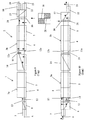
- FIG. 1 An example of a dispersion free optical interleaver using a Solc filter will be described, with reference to Figures 1 and 2.
- This specific example cascades a first optical filter, generally indicated at 1, having frequency transfer functions of H 1 (f) with a second optical filter, generally indicated at 2, with a frequency transfer function of H 2 (f).
- the wave-plates 4 and 5 are oriented at 45° and 105°, respectively, with respect to the polarization of the incoming beams of light.
- the thickness L and the orientations of the wave-plates 4 and 5 are chosen to provide a desired FSR, depending on the birefringence of the wave-plate material.
- a beam of light including channels ⁇ 1 to ⁇ n , is launched from fiber 6, through collimating lens 7, into a beam splitter 8.
- the lens 7 is preferably a 1 ⁇ 4-pitch GRIN lens
- the beam splitter is preferably a walk-off crystal, e.g. TiO 2 or YVO 4 .
- the beam splitter 8 the beam is separated into two orthogonally polarized sub-beams 11 and 12.
- the state of polarization of one of the sub-beams, sub-beam 11 in the illustrated embodiment is rotated by 90° in half-wave plate 13, so that both sub-beams have the same polarization for entry into the first birefringent stack 3a.
- both sub-beams 11 and 12 are vertically polarized before entering the first birefringent stack 3a.
- one set of channels e.g. the even channels ⁇ 2 , ⁇ 4 , ⁇ 6 ...
- the other set of channels e.g. the odd channels ⁇ 1 , ⁇ 3 , ⁇ 5 ...
- a second beam splitter 14 e.g. a walk-off crystal or a polarization beam splitter, is used to further sub-divide the sub-beams 11 and 12 into 11o, 11e, 12o and 12e.
- Half-wave plate 15 is positioned in the path of sub-beams 11e and 12e ensuring that all of the sub-beams 11o, 11e, 12o and 12e enter the second birefringent stack 3b with the same polarization as each other and with a polarization orthogonal to sub-beams 11 and 12 as they entered the first stack 3a.
- all of the sub-beams enter the second stack 3b horizontally polarized.
- the polarizations thereof remain the same, i.e. horizontal.
- a half-wave plate 16 is used to rotate the polarization of one of sub-beams 11o or 12o, in this case 12o, so that a beam combiner 17 can bring the two sub-beams together for outputting the odd channels via focusing lens 18 and fiber 19.
- a half-wave plate 21 rotates the polarization of one of sub-beams 11e or 12e, in this case 11e, so that the beam combiner 17 can combine the two sub-beams for outputting the even channels via focusing lens 22 and fiber 23
- the illustrated embodiment is shown in operation with vertically polarized sub-beams 11 and 12 as input; however, it would be obvious to adapt the device for any input polarization by rearranging the remainder of the elements accordingly.
- H 1 (f) e 3i ⁇ .f .( ⁇ 0 + ⁇ 1 .e i ⁇ .f + ⁇ 2 .e 2i ⁇ .f + ⁇ 3 .e 3i ⁇ .f )
- ⁇ 1 45 °
- ⁇ 2 60 °
- ⁇ 3 -105 °
- the elements can be positioned in various arrangements to satisfy this requirement.
- the simplest arrangement would be to simply rotate the polarization of the beams entering the second filter by 90° so as to be orthogonal to when the original beam entered the first filter.
- Figures 3 and 4 illustrate this example, wherein wave plates 4a and 5a from the first filter 3a have the same orientations as wave plates 4b and 5b from the second filter 3b, while the polarization of the signal, represented by the doubleheaded arrow, is rotated by 90°.
- This is the arrangement disclosed in the above-identified embodiment.
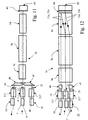
- This arrangement also provides the possibility of passing the beam through the same birefringent stack twice, with a polarization adjustment in between passes, see Figures 7 and 8.
- FIG. 7 and 8 The embodiment illustrated in Figures 7 and 8 is similar to the embodiment illustrated in Figures 1 and 2, wherein an input beam is launched into port 7, divided into sub-beams 11 and 12 in walk-off crystal 8, directed through birefringent elements 4 and 5, and divided into sub-beams 11o, 11e, 12o and 12e using a polarization beam splitter 114.
- one pair of sub-beams 11e and 12e is combined using half-wave plate 31 and walk-off crystal 32, and transmitted back to the front end of the filter 3 using lenses 33 and 34 and waveguide 35.
- the other pair of sub-beams 11o and 12o are combined using half-wave plate 16 and walk-off crystal 17, and transmitted to the front end of filter 3 using lenses 38 and 39 and waveguide 40.
- half-wave plate 41 is positioned in the path of one of each pair to ensure that the sub-beams enter the wave plates 4 and 5 for a second pass with a polarization orthogonal to the polarization that the sub-beams 11 and 12 had upon entering the wave plates 4 and 5 for the first pass.
- the odd channel sub-beams pass through the birefringent elements 4 and 5 for a second pass, get recombined by waveplate 16 and beam combiner 17, and are output via lens 18.
- the even channel sub-beams pass through the birefringent elements 4 and 5 for a second time, get recombined by waveplate 31 and beams combiner 32, and are output via lens 22.
- Figure 5 and 6 illustrate this example, wherein the polarization of the beams remains constant, while the orientations of the wave plates 4b and 5b are different than those of wave plates 4a and 5a, respectively.
- This embodiment is illustrated in Figures 9 and 10, which appear in the side and top views to be identical to Figures 1 and 2, except for half-wave plate 15 being positioned in the paths of sub-beams 11o and 12o to ensure that the polarizations of all of the beams entering both stages of the cascaded filter are the same.
- the important difference in the device illustrated Figures 9 and 10, which can be seen in Figs 5 and 6, is the different orientations of the crystal axes of the wave plates 4a, 4b, 5a and 5b.
- a set of solutions is, for example:
- the combined beam is launched from fiber 6 along a first path through lens 7, walk-off crystal 8 and birefringent elements 4a and 5a to polarization beam splitter 14, wherein it is divided into two orthogonally polarized pairs of sub-beams 11o and 12o, and 11e and 12e.
- all of the sub-beams pass through quarter wave plate 44, and are reflected by mirror 45.
- Prismatic walk-off crystals 46 and 47 are used to direct the pairs of sub-beams to their respective combining crystals 117 and 217, respectively, for output via lenses 18 and 22, respectively.
- Any optical filter having any desired intensity profile and having no chromatic dispersion can be made using this technique.
- H 2 (f) is then determined, satisfying the principles of the present invention, to yield the desired result for the cascaded filter H 2 (f).
- H 1 (f) H T (f) (dispersion free and
- H 1 (f) and H 2 (f) are done by proper choice of coupling ratios and arm lengths (in the case of waveguide lattice filter) or of waveplate orientations and thicknesses (in the case of birefringent Solc filter).
- the present invention is exemplified by a pair of cascaded lattice (or Fourier transform-based) optical filters 51 and 52.
- the first filter 51 includes a first waveguide 53, a second waveguide 54, and three couplers 56, 57 and 58a.
- the first waveguide includes a first delay line 59 between the first and second couplers 56 and 57, and a second delay line 61 between the second and third couplers 57 and 58a.
- the first delay line 59 is ⁇ L longer than the distance L between couplers 56 and 57 on the second waveguide 54.
- the second delay line 61 is 2 ⁇ L longer than the distance L between couplers 57 and 58 on the second waveguide.
- Optical fibers and planar waveguides are examples of the different kinds of waveguides that can be used.
- the second filter 52 includes a third waveguide 62 extending from the first waveguide, a fourth waveguide 63 extending from the second waveguide, and three couplers 58b, 64 and 65.
- the fourth waveguide includes a third delay line 67 between couplers 58b and 64, identical to the first delay line 59, and a fourth delay line 68 between couplers 64 and 65, identical to the second delay line 61.
- each coupler has a coupling ratio of 50:50, which would be dispersion free; however according to the present invention the coupling ratios for the various couplers can have almost any value dependent upon the requirements for the output; however, the coupling ratios of the first and fourth couplers 56 and 58b should be substantially the same, while the coupling ratios of the second and fifth couplers 57 and 64, should also be substantially the same. The coupling ratios of the third coupler 58a and the sixth coupler 65 should also be substantially the same. Accordingly, the second optical filter 52 is the inverse of the first optical filer 51. This arrangement results in a symmetric pulse response and, therefore, a dispersion free response.
- the first and second filters 51 and 52 can include other delay lines, such as in Figures 14 and 15.
- the first filter 51 in Figure 14, includes another coupler 71 and an additional delay line 72 of length L+2 ⁇ L.
- the second filter 52 has another coupler 73, and an inverted delay line 74 of length L+2 ⁇ L corresponding to delay line 72.
- couplers 56 and 58b would have the same coupling ratio
- couplers 57 and 64 would have the same coupling ratio
- couplers 71 and 65 would have the same coupling ratio
- couplers 58a and 73 would have the same coupling ratio.
- the first filter 51 has an additional delay line 76 of length L+4 ⁇ L, while the second filter 52 has a corresponding inverted delay line 77.
- a single coupler 58 can be used instead of the third and fourth couplers 58a and 58b (See Figure 15). If the first and second filters only have two delay lines each, e.g. ⁇ L and 2 ⁇ L, the first, the third and the sixth couplers 56, 58, 65 would all have the same coupling ratio. However, if the first and second filters have more than two delay lines each, then the single coupler 58 will have no effect on the relationship between the first six couplers. In this case the last coupler of the first filter will be the initial coupler, i.e. the fourth coupler, of the second filter.
- This technique enables the realization of optical filters of any arbitrary intensity response, while keeping a linear phase response.
Landscapes
- Physics & Mathematics (AREA)
- General Physics & Mathematics (AREA)
- Optics & Photonics (AREA)
- Engineering & Computer Science (AREA)
- Microelectronics & Electronic Packaging (AREA)
- Chemical & Material Sciences (AREA)
- Dispersion Chemistry (AREA)
Applications Claiming Priority (2)
| Application Number | Priority Date | Filing Date | Title |
|---|---|---|---|
| US20207700P | 2000-05-05 | 2000-05-05 | |
| US202077P | 2000-05-05 |
Publications (2)
| Publication Number | Publication Date |
|---|---|
| EP1152265A2 true EP1152265A2 (fr) | 2001-11-07 |
| EP1152265A3 EP1152265A3 (fr) | 2003-12-17 |
Family
ID=22748409
Family Applications (1)
| Application Number | Title | Priority Date | Filing Date |
|---|---|---|---|
| EP01304152A Withdrawn EP1152265A3 (fr) | 2000-05-05 | 2001-05-08 | Filtres optiques sans dispersion |
Country Status (4)
| Country | Link |
|---|---|
| US (1) | US6721477B2 (fr) |
| EP (1) | EP1152265A3 (fr) |
| CN (1) | CN1348277A (fr) |
| CA (1) | CA2344549A1 (fr) |
Cited By (3)
| Publication number | Priority date | Publication date | Assignee | Title |
|---|---|---|---|---|
| US6809863B2 (en) * | 2001-06-07 | 2004-10-26 | Cirvine Corporation | Low dispersion filters |
| WO2004104664A1 (fr) * | 2003-05-16 | 2004-12-02 | Hoya Corporation | Dispositif de polarisation |
| US6956988B2 (en) | 1998-08-21 | 2005-10-18 | Avanex Corporation | Optical interleaver |
Families Citing this family (4)
| Publication number | Priority date | Publication date | Assignee | Title |
|---|---|---|---|---|
| US20030016425A1 (en) * | 2001-07-19 | 2003-01-23 | Tan Tun Sein | Polarization diversity receiver with planar waveguide and polarizing beam splitter |
| US6768843B1 (en) * | 2002-08-16 | 2004-07-27 | Wavesplitter Technologies, Inc. | Cascaded fourier filter interleaver having enhanced performance |
| CN100405104C (zh) * | 2003-12-15 | 2008-07-23 | 中国科学院上海光学精密机械研究所 | 基于空间双折射元件的可调谐带通滤波器 |
| CN102866464B (zh) * | 2012-09-25 | 2014-03-12 | 中国科学院西安光学精密机械研究所 | 基于光束偏移器的空间激光通信双折射滤波方法 |
Citations (2)
| Publication number | Priority date | Publication date | Assignee | Title |
|---|---|---|---|---|
| US5694233A (en) * | 1996-07-23 | 1997-12-02 | Macro-Vision Communications, Llc | Switchable wavelength router |
| EP1136857A2 (fr) * | 2000-03-03 | 2001-09-26 | E-Tek Dynamics, Inc. | Entrelaceur/désentrelaceur provoquant une dispersion petite ou nulle des signaux optiques |
Family Cites Families (5)
| Publication number | Priority date | Publication date | Assignee | Title |
|---|---|---|---|---|
| US4343969A (en) * | 1978-10-02 | 1982-08-10 | Trans-Data Associates | Apparatus and method for articulatory speech recognition |
| JPS60428A (ja) * | 1983-06-17 | 1985-01-05 | Fujitsu Ltd | 超高速度光位相変調波復調方式 |
| JPS60429A (ja) * | 1983-06-17 | 1985-01-05 | Fujitsu Ltd | 超高速度光位相変調波復調方式 |
| US5216529A (en) * | 1992-01-15 | 1993-06-01 | Bell Communications Research, Inc. | Holographic code division multiple access |
| US7194162B2 (en) * | 2002-02-22 | 2007-03-20 | Neophotonics Corporation | Filter response optimization for an arrayed waveguide grating device by adjusting grating optical path length at nanometer scale |
-
2001
- 2001-05-03 US US09/999,911 patent/US6721477B2/en not_active Expired - Lifetime
- 2001-05-03 CA CA002344549A patent/CA2344549A1/fr not_active Abandoned
- 2001-05-08 CN CN01121248A patent/CN1348277A/zh active Pending
- 2001-05-08 EP EP01304152A patent/EP1152265A3/fr not_active Withdrawn
Patent Citations (2)
| Publication number | Priority date | Publication date | Assignee | Title |
|---|---|---|---|---|
| US5694233A (en) * | 1996-07-23 | 1997-12-02 | Macro-Vision Communications, Llc | Switchable wavelength router |
| EP1136857A2 (fr) * | 2000-03-03 | 2001-09-26 | E-Tek Dynamics, Inc. | Entrelaceur/désentrelaceur provoquant une dispersion petite ou nulle des signaux optiques |
Non-Patent Citations (2)
| Title |
|---|
| KANAME JINGUJI ET AL: "SYNTHESIS OF COHERENT TWO-PORT LATTICE-FORM OPTICAL DELAY-LINE CIRCUIT" JOURNAL OF LIGHTWAVE TECHNOLOGY, IEEE. NEW YORK, US, vol. 13, no. 1, 1995, pages 73-82, XP000494974 ISSN: 0733-8724 * |
| SCHEERER C: "PHASE DISTORTIONS IN OPTICAL TRANSMISSION SYSTEMS PHASENVERZERRUNGEN IN OPTISCHEN UEBERTRAGUNGSSYSTEMEN" FREQUENZ, SCHIELE UND SCHON GMBH. BERLIN, DE, vol. 54, no. 1/2, January 2000 (2000-01), pages 42-46, XP000954240 ISSN: 0016-1136 * |
Cited By (4)
| Publication number | Priority date | Publication date | Assignee | Title |
|---|---|---|---|---|
| US6956988B2 (en) | 1998-08-21 | 2005-10-18 | Avanex Corporation | Optical interleaver |
| US7257287B2 (en) | 1998-08-21 | 2007-08-14 | Avanex Corporation | Optical interleaver |
| US6809863B2 (en) * | 2001-06-07 | 2004-10-26 | Cirvine Corporation | Low dispersion filters |
| WO2004104664A1 (fr) * | 2003-05-16 | 2004-12-02 | Hoya Corporation | Dispositif de polarisation |
Also Published As
| Publication number | Publication date |
|---|---|
| EP1152265A3 (fr) | 2003-12-17 |
| US20030198437A1 (en) | 2003-10-23 |
| US6721477B2 (en) | 2004-04-13 |
| CN1348277A (zh) | 2002-05-08 |
| CA2344549A1 (fr) | 2001-11-05 |
Similar Documents
| Publication | Publication Date | Title |
|---|---|---|
| Cao et al. | Interleaver technology: comparisons and applications requirements | |
| US6690513B2 (en) | Rhomb interleaver | |
| US6455841B2 (en) | Optical wavelength router based on polarization interferometer | |
| US6570711B2 (en) | Virtual waveplate and optical channel interleaver formed therewith | |
| US7433557B2 (en) | Tunable optical add/drop multiplexer | |
| US6690846B2 (en) | Dispersion-compensated optical wavelength router | |
| US6498680B1 (en) | Compact tunable optical wavelength interleaver | |
| US6587266B2 (en) | Bi-directional isolator | |
| US20030035605A1 (en) | Double pass arrangement for a liquid crystal device | |
| JPS6173919A (ja) | 複屈折の光学波長マルチプレクサおよびデマルチプレクサ | |
| US20030021526A1 (en) | Dynamic dispersion compensator | |
| JPS62105116A (ja) | 平坦化された帯域をもつ複屈折の光学的マルチプレクサ | |
| US7058304B2 (en) | Bi-directional cross-connect | |
| US20020126935A1 (en) | Tunable periodic filter | |
| US7173763B2 (en) | Optical interleaver and filter cell design with enhanced clear aperture | |
| US6721477B2 (en) | Dispersion-free optical filters | |
| JP2002023111A (ja) | 偏光ビームスプリッター/コンバイナ | |
| US6684002B2 (en) | Method and apparatus for an optical filter | |
| US6798551B2 (en) | Gires-Tournois interferometer with faraday rotators for optical signal interleaver | |
| US6535324B1 (en) | Bi-directional wavelength-selective optical data apparatus | |
| US20020041574A1 (en) | Multiplexing and / or demultiplexing apparatus | |
| US20020159151A1 (en) | Optical interleaver using mach-zehnder interferometry | |
| US7106508B2 (en) | Hybrid cell | |
| US20020171931A1 (en) | Integrated optical device with polarization based signal routing | |
| JPH0836157A (ja) | 可変波長フィルタ |
Legal Events
| Date | Code | Title | Description |
|---|---|---|---|
| PUAI | Public reference made under article 153(3) epc to a published international application that has entered the european phase |
Free format text: ORIGINAL CODE: 0009012 |
|
| AK | Designated contracting states |
Kind code of ref document: A2 Designated state(s): AT BE CH CY DE DK ES FI FR GB GR IE IT LI LU MC NL PT SE TR |
|
| AX | Request for extension of the european patent |
Free format text: AL;LT;LV;MK;RO;SI |
|
| RIC1 | Information provided on ipc code assigned before grant |
Ipc: 7G 02B 6/34 B Ipc: 7G 02B 5/20 A |
|
| PUAL | Search report despatched |
Free format text: ORIGINAL CODE: 0009013 |
|
| AK | Designated contracting states |
Kind code of ref document: A3 Designated state(s): AT BE CH CY DE DK ES FI FR GB GR IE IT LI LU MC NL PT SE TR |
|
| AX | Request for extension of the european patent |
Extension state: AL LT LV MK RO SI |
|
| AKX | Designation fees paid | ||
| REG | Reference to a national code |
Ref country code: DE Ref legal event code: 8566 |
|
| STAA | Information on the status of an ep patent application or granted ep patent |
Free format text: STATUS: THE APPLICATION IS DEEMED TO BE WITHDRAWN |
|
| 18D | Application deemed to be withdrawn |
Effective date: 20040618 |