EP1152245A2 - Micromachined mechanical structure and device using the same - Google Patents
Micromachined mechanical structure and device using the same Download PDFInfo
- Publication number
- EP1152245A2 EP1152245A2 EP01401050A EP01401050A EP1152245A2 EP 1152245 A2 EP1152245 A2 EP 1152245A2 EP 01401050 A EP01401050 A EP 01401050A EP 01401050 A EP01401050 A EP 01401050A EP 1152245 A2 EP1152245 A2 EP 1152245A2
- Authority
- EP
- European Patent Office
- Prior art keywords
- elongation
- suspension
- beams
- axial line
- axis
- Prior art date
- Legal status (The legal status is an assumption and is not a legal conclusion. Google has not performed a legal analysis and makes no representation as to the accuracy of the status listed.)
- Granted
Links
Images


Classifications
-
- G—PHYSICS
- G01—MEASURING; TESTING
- G01P—MEASURING LINEAR OR ANGULAR SPEED, ACCELERATION, DECELERATION, OR SHOCK; INDICATING PRESENCE, ABSENCE, OR DIRECTION, OF MOVEMENT
- G01P15/00—Measuring acceleration; Measuring deceleration; Measuring shock, i.e. sudden change of acceleration
- G01P15/02—Measuring acceleration; Measuring deceleration; Measuring shock, i.e. sudden change of acceleration by making use of inertia forces using solid seismic masses
- G01P15/08—Measuring acceleration; Measuring deceleration; Measuring shock, i.e. sudden change of acceleration by making use of inertia forces using solid seismic masses with conversion into electric or magnetic values
-
- B—PERFORMING OPERATIONS; TRANSPORTING
- B81—MICROSTRUCTURAL TECHNOLOGY
- B81B—MICROSTRUCTURAL DEVICES OR SYSTEMS, e.g. MICROMECHANICAL DEVICES
- B81B3/00—Devices comprising flexible or deformable elements, e.g. comprising elastic tongues or membranes
- B81B3/0035—Constitution or structural means for controlling the movement of the flexible or deformable elements
- B81B3/0051—For defining the movement, i.e. structures that guide or limit the movement of an element
-
- B—PERFORMING OPERATIONS; TRANSPORTING
- B81—MICROSTRUCTURAL TECHNOLOGY
- B81B—MICROSTRUCTURAL DEVICES OR SYSTEMS, e.g. MICROMECHANICAL DEVICES
- B81B2201/00—Specific applications of microelectromechanical systems
- B81B2201/02—Sensors
- B81B2201/0228—Inertial sensors
- B81B2201/0235—Accelerometers
-
- B—PERFORMING OPERATIONS; TRANSPORTING
- B81—MICROSTRUCTURAL TECHNOLOGY
- B81B—MICROSTRUCTURAL DEVICES OR SYSTEMS, e.g. MICROMECHANICAL DEVICES
- B81B2203/00—Basic microelectromechanical structures
- B81B2203/03—Static structures
- B81B2203/0307—Anchors
-
- B—PERFORMING OPERATIONS; TRANSPORTING
- B81—MICROSTRUCTURAL TECHNOLOGY
- B81B—MICROSTRUCTURAL DEVICES OR SYSTEMS, e.g. MICROMECHANICAL DEVICES
- B81B2203/00—Basic microelectromechanical structures
- B81B2203/05—Type of movement
- B81B2203/051—Translation according to an axis parallel to the substrate
-
- G—PHYSICS
- G01—MEASURING; TESTING
- G01P—MEASURING LINEAR OR ANGULAR SPEED, ACCELERATION, DECELERATION, OR SHOCK; INDICATING PRESENCE, ABSENCE, OR DIRECTION, OF MOVEMENT
- G01P15/00—Measuring acceleration; Measuring deceleration; Measuring shock, i.e. sudden change of acceleration
- G01P15/02—Measuring acceleration; Measuring deceleration; Measuring shock, i.e. sudden change of acceleration by making use of inertia forces using solid seismic masses
- G01P15/08—Measuring acceleration; Measuring deceleration; Measuring shock, i.e. sudden change of acceleration by making use of inertia forces using solid seismic masses with conversion into electric or magnetic values
- G01P2015/0805—Measuring acceleration; Measuring deceleration; Measuring shock, i.e. sudden change of acceleration by making use of inertia forces using solid seismic masses with conversion into electric or magnetic values being provided with a particular type of spring-mass-system for defining the displacement of a seismic mass due to an external acceleration
- G01P2015/0808—Measuring acceleration; Measuring deceleration; Measuring shock, i.e. sudden change of acceleration by making use of inertia forces using solid seismic masses with conversion into electric or magnetic values being provided with a particular type of spring-mass-system for defining the displacement of a seismic mass due to an external acceleration for defining in-plane movement of the mass, i.e. movement of the mass in the plane of the substrate
- G01P2015/0811—Measuring acceleration; Measuring deceleration; Measuring shock, i.e. sudden change of acceleration by making use of inertia forces using solid seismic masses with conversion into electric or magnetic values being provided with a particular type of spring-mass-system for defining the displacement of a seismic mass due to an external acceleration for defining in-plane movement of the mass, i.e. movement of the mass in the plane of the substrate for one single degree of freedom of movement of the mass
- G01P2015/0814—Measuring acceleration; Measuring deceleration; Measuring shock, i.e. sudden change of acceleration by making use of inertia forces using solid seismic masses with conversion into electric or magnetic values being provided with a particular type of spring-mass-system for defining the displacement of a seismic mass due to an external acceleration for defining in-plane movement of the mass, i.e. movement of the mass in the plane of the substrate for one single degree of freedom of movement of the mass for translational movement of the mass, e.g. shuttle type
Landscapes
- Physics & Mathematics (AREA)
- General Physics & Mathematics (AREA)
- Engineering & Computer Science (AREA)
- Computer Hardware Design (AREA)
- Microelectronics & Electronic Packaging (AREA)
- Micromachines (AREA)
- Vibration Prevention Devices (AREA)
Abstract
Description
L'invention se situe dans le domaine des structures mécaniques et plus particulièrement celles qui sont micro-usinées, comprenant une masse mobile reliée par au moins une poutre ayant deux extrémités à un ancrage, la poutre ayant l'une de ses extrémités reliée à la masse mobile et l'autre extrémité reliée à l'ancrage. Elle est relative aussi à un dispositif en particulier un capteur incorporant la structure.The invention lies in the field of mechanical structures and more particularly those which are micromachined, comprising a moving mass connected by at least one beam having two ends at an anchor, the beam having one of its ends connected to the moving mass and the other end connected to anchoring. It also relates to a device in in particular a sensor incorporating the structure.
Il existe des oscillateurs mécaniques dans lesquels la force appliquée à une masse mobile et le mouvement de cette masse mobile sont liés par une relation non linéaire, dans ce cas la raideur d'une poutre couplant la masse mobile à une structure fixe de l'oscillateur est variable en fonction de l'amplitude du déplacement de la masse mobile. Cet effet de la variation de la raideur de la poutre est d'autant plus sensible que l'amplitude du mouvement de la masse mobile augmente. L'effet induit peut être sublinéaire ou supralinéaire. La relation non linéaire entre la force appliquée à la masse mobile et l'amplitude du mouvement de la masse mobile induit qu'aux fréquences proches de la résonance pour une fréquence donnée, on peut avoir deux amplitudes possibles du mouvement. Le mouvement devient donc instable. Lorsqu'une structure est excitée au voisinage de sa fréquence de résonance, l'amplitude du mouvement de la masse mobile par rapport à la position statique de la masse mobile est amplifiée par un facteur qu'on appelle "facteur de qualité Q". Ce facteur est d'autant plus fort que les pertes d'énergie dans la structure mécanique sont faibles. Cette amplification est mise à profit pour obtenir de fortes amplitudes d'oscillation avec de faibles forces d'excitation. La fonction de transfert mécanique (mouvement en fonction de la fréquence d'excitation) devient asymétrique au voisinage de la fréquence de résonance puis présente un caractère instable. Le phénomène de non linéarité de la liaison entre la force appliquée à la masse mobile et l'amplitude du mouvement de la masse mobile limite l'amplitude du mouvement que l'on peut accepter si l'on veut garder un caractère stable au mouvement. On observe par exemple des micro-structures en silicium comportant des poutres de type encastré-encastré de quelques centaines de µm de longueur dont l'oscillation devient instable pour des amplitudes de mouvement de quelques µm. Pour certains systèmes, cela limite des performances importantes, comme par exemple la sensibilité d'un dispositif de mesure incorporant une telle structure. Pour limiter le phénomène de non linéarité on a cherché à limiter l'amplitude des oscillations de la masse mobile. On reste ainsi dans le domaine linéaire et on peut avoir un mouvement stable. Ainsi, le brevet DE-202 445 2 B attribué à IBM Corp. décrit un oscillateur électromécanique monolithique comprenant une partie semi-conductrice dont la fréquence de résonance mécanique détermine la fréquence d'oscillation. Un circuit de contrôle de l'amplitude d'oscillation est intégré dans l'oscillateur. Le circuit de contrôle de l'amplitude des oscillations contrôle l'énergie d'excitation c'est-à-dire le flux de courant à travers une résistance de chauffage, en fonction d'une valeur seuil et de l'amplitude de l'oscillation réelle constatée. Un autre exemple de limitation de l'amplitude des oscillations est décrit dans le brevet SU 493 770 A attribué à KAUN POLY. Dans ce brevet, l'amplitude des vibrations est captée. Lorsque l'amplitude des vibrations dépasse un seuil prédéterminé, un moyen change la rigidité d'un système élastique de telle sorte que la fréquence de résonance est changée et donc on limite l'amplitude des vibrations. Des exemple connus de structures mécaniques incorporant une masse mobile oscillante seront maintenant décrits en référence aux figures 1A à 1D. Sur ces figures des numéros de références identiques désignent des éléments ayant les mêmes fonctions.There are mechanical oscillators in which the force applied to a moving mass and the movement of this moving mass are linked by a nonlinear relation, in this case the stiffness of a beam coupling the moving mass to a fixed structure of the oscillator is variable depending on the amplitude displacement of the moving mass. This effect of the variation in the stiffness of the beam is all the more sensitive that the range of motion of the mass mobile increases. The induced effect can be sublinear or supralinear. The non-linear relationship between the force applied to the moving mass and the amplitude of the movement of the moving mass induced only at frequencies close to resonance for a given frequency, we can have two possible ranges of motion. The movement therefore becomes unstable. When a structure is excited in the vicinity of its resonant frequency, the range of motion of the moving mass relative at the static position of the moving mass is amplified by a factor called "Q quality factor". This factor is all the stronger as the energy losses in the mechanical structure are weak. This amplification is used to obtain strong oscillation amplitudes with low forces of excitement. The mechanical transfer function (movement as a function of the excitation frequency) becomes asymmetric near the frequency of resonance then presents an unstable character. The phenomenon of non-linearity of the connection between the force applied to the moving mass and range of motion of moving mass limits the range of motion that we can accept if we want to keep a character stable to movement. We observe for example silicon micro-structures comprising beams of recessed-recessed type of a few hundred µm length whose oscillation becomes unstable for range of motion of a few µm. For some people systems, this limits important performances, like for example the sensitivity of a device measure incorporating such a structure. To limit the phenomenon of non linearity we tried to limit the amplitude of the oscillations of the moving mass. We so stays in the linear domain and we can have a stable movement. Thus, patent DE-202 445 2 B attributed to IBM Corp. describes an oscillator electromechanical monolithic comprising a part semiconductor whose resonant frequency mechanics determines the frequency of oscillation. A oscillation amplitude control circuit is integrated in the oscillator. The control circuit of the amplitude of the oscillations controls the energy excitation i.e. the flow of current through a heating resistor, depending on a value threshold and amplitude of the actual oscillation noted. Another example of limitation of the amplitude of the oscillations is described in the patent SU 493 770 Awarded to KAUN POLY. In this patent, the amplitude of the vibrations is captured. When the amplitude of the vibrations exceeds a threshold predetermined, a means changes the rigidity of a system elastic so that the resonant frequency is changed and therefore we limit the amplitude of vibrations. Known examples of mechanical structures incorporating an oscillating moving mass will now described with reference to Figures 1A to 1D. In these figures identical reference numbers denote elements having the same functions.
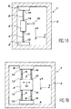
La figure 1A représente une structure mécanique 1 incorporant un cadre fixe 2 dans lequel oscille une masse mobile 3. La masse mobile 3 est reliée par l'intermédiaire de poutres 4, 5, au cadre fixe 2. La direction du mouvement représentée par une double flèche 10 est perpendiculaire aux poutres 4, 5 et se situe dans le plan XOY de la figure. Le mouvement de la masse mobile est parallèle à la direction OY. Les extrémités 11 et 12 de la poutre 4 sont reliées respectivement à la masse mobile 3 et à un ancrage 8 fixe dans la direction OY du mouvement de la masse mobile. De même, des extrémités 13, 14 de la poutre 5 sont reliées respectivement à la masse mobile et à un ancrage 9 fixe dans la direction OY. La figure 1B, représente une structure mécanique 1 comportant une masse mobile 3 comme représenté figure 1A, mais dans le cas de la figure 1B la masse mobile 3 est reliée par un ensemble de quatre poutres aux ancrages 8 et 9 respectivement, il y a donc deux poutres additionnelles 6, 7, ayant chacune des extrémités 15, 16 ; 17, 18 respectivement, ces poutres couplant la masse mobile 3 aux ancrages 8,9 respectivement. Les figures 1C et 1D représentent également une structure mécanique 1 incorporant une masse mobile 3 dans laquelle les poutres reliant la masse mobile 3 aux ancrages 8, 9 respectivement ne sont pas des poutres droites. La forme des poutres 4, 5 ou 6, 7 représentée sur les figures 1C et 1D permet une déformation de la poutre dans le plan XOY et par conséquent une plus grande amplitude des vibrations de la masse mobile 3. Cette plus grande amplitude des vibrations de la masse mobile 3 se fait sans qu'apparaissent des phénomènes non linéaires ceci en raison précisément de la forme des poutres 4, 5, 6 ou 7. Ce genre de poutres déformables que l'on peut trouver par exemple dans la demande de brevet WO 95/34798 attribuée à BOSCH présente l'inconvénient d'avoir une masse mobile 3 qui oscille non seulement dans la direction Y du plan XOY mais aussi dans la direction X de ce même plan. Il en résulte des phénomènes parasites qui viennent perturber le signal que l'on peut obtenir avec un dispositif en particulier un capteur disposant d'une telle structure mécanique. Ces phénomènes parasites peuvent se traduire par exemple par un déplacement de la fréquence de résonance, par l'apparition de modes de déformation mécanique pouvant éventuellement se coupler avec le mode d'excitation recherché dans la direction Y, et enfin par une sensibilité accrue aux accélérations suivant plusieurs axes. Dans ce dernier cas, il en résulte une réduction du contrôle de la directivité du mouvement.Figure 1A shows a mechanical structure 1 incorporating a fixed frame 2 in which a moving mass 3. The moving mass 3 is connected by beams 4, 5, with a fixed frame 2. The direction of movement represented by a double arrow 10 is perpendicular to beams 4, 5 and is located in the plane XOY of the figure. The movement of the moving mass is parallel to the direction OY. The ends 11 and 12 of beam 4 are connected respectively to the moving mass 3 and to an anchor 8 fixed in the direction OY of the mass movement mobile. Likewise, the ends 13, 14 of the beam 5 are connected respectively to the moving mass and to a anchor 9 fixed in the direction OY. Figure 1B, represents a mechanical structure 1 comprising a moving mass 3 as shown in FIG. 1A, but in the case of Figure 1B the moving mass 3 is connected by a set of four beams at anchors 8 and 9 respectively, so there are two additional beams 6, 7, each having ends 15, 16; 17, 18 respectively, these beams coupling the moving mass 3 at anchors 8.9 respectively. Figures 1C and 1D also represent a mechanical structure 1 incorporating a moving mass 3 in which the beams connecting the moving mass 3 to the anchors 8, 9 respectively are not straight beams. The shape of the beams 4, 5 or 6, 7 shown on the Figures 1C and 1D allows a deformation of the beam in the XOY plane and therefore greater amplitude of the vibrations of the moving mass 3. This greater amplitude of the vibrations of the moving mass 3 is done without appearing phenomena not linear this precisely because of the shape of the beams 4, 5, 6 or 7. This kind of deformable beams which can be found for example in the request for WO 95/34798 attributed to BOSCH present the disadvantage of having a moving mass 3 which oscillates not only in the Y direction of the XOY plane but also in the X direction of this same plane. It results from parasitic phenomena which disturb the signal that can be obtained with a device in particular a sensor having such a structure mechanical. These parasitic phenomena can be translated for example by shifting the frequency of resonance, by the appearance of deformation modes mechanical which can possibly be coupled with the desired excitation mode in the Y direction, and finally by an increased sensitivity to accelerations along several axes. In the latter case, it results in a reduction in the control of the directivity of the movement.
Le problème de la dépendance entre l'amplitude des vibrations de la masse oscillante et la fréquence de vibration de cette masse est abordée dans le brevet US-A-5 902 012 attribué à BOEING NORTH AMERICAN.The problem of the dependence between the amplitude oscillating mass vibrations and frequency vibration of this mass is discussed in the patent US-A-5,902,012 assigned to BOEING NORTH AMERICAN.
Il est observé dans ce brevet (col. 1, lignes 44-48) que l'amplitude de la vibration peut atteindre 20 % de la longueur des poutres de suspension de la masse oscillante et que dans ces conditions, l'élongation des poutres dans leur direction axiale ne peut plus être négligée. Pour remédier à cet état de fait, il est proposé dans ce brevet (col. 1, ligne 63 - col. 2, ligne 2) de donner à la poutre de suspension une meilleure aptitude à l'élongation et pour cela de modifier la poutre ou encore la configuration du cadre ou de la masse à l'endroit où cette poutre de suspension est attachée.It is observed in this patent (col. 1, lines 44-48) that the amplitude of the vibration can reach 20% of the length of the suspension beams of the oscillating mass and that under these conditions, the elongation of the beams in their axial direction does not can no longer be overlooked. To remedy this state of fact, it is proposed in this patent (col. 1, line 63 - collar. 2, line 2) to give the suspension beam better elongation ability and therefore modify the beam or the frame configuration or mass where this beam suspension is attached.
Cette meilleure aptitude à l'élongation est obtenue soit :
- en donnant à chaque poutre de suspension une forme incurvée dans le plan de vibration de la masse oscillante comme représenté en figure 1 de ce brevet ; ou encore
- en prévoyant des parties permettant une relaxation de la contrainte d'élongation, par exemple sous forme de découpes effectuées au niveau des liaisons entre la poutre et le cadre fixe et/ou la masse oscillante ou encore sous forme de découpes effectuées sur la poutre d'élongation, comme représenté figure 2 à 5 de ce brevet.
- by giving each suspension beam a curved shape in the vibration plane of the oscillating mass as shown in Figure 1 of this patent; or
- by providing parts allowing relaxation of the elongation stress, for example in the form of cuts made at the connections between the beam and the fixed frame and / or the oscillating mass or even in the form of cuts made on the beam elongation, as shown in FIGS. 2 to 5 of this patent.
On remarque que dans tous les exemples représentés, les moyens d'élongation présentent une symétrie relativement à la raideur. On veut dire par là que la résistance à l'élongation a la même valeur pour une même valeur de traction effectuée selon la ligne axiale de la poutre de suspension, exercée dans un sens ou dans le sens opposé. Exprimé autrement, la déformation des moyens d'élongation est la même que la traction soit effectuée dans un sens ou dans le sens opposé.We note that in all the examples shown, the elongation means have a symmetry with respect to stiffness. We mean by that that the resistance to elongation has the same value for the same traction value carried out along the line axial of the suspension beam, exerted in one direction or in the opposite direction. Expressed otherwise, the deformation of the elongation means is the same as the pull either in one direction or in the direction opposite.
L'invention vise à offrir une structure mécanique dans laquelle la masse mobile oscillante se déplace selon un axe connu sans se déplacer dans d'autres directions et ceci selon un mouvement linéaire ne présentant pas les instabilités que l'on peut observer lorsque le mouvement n'est pas linéaire. L'invention vise à offrir ce mouvement linéaire avec une amplitude d'oscillation plus importante que l'amplitude d'oscillation que l'on peut obtenir avec les structures mécaniques de l'art antérieur comme décrite par exemple dans les figures 1A et 1B ou dans le brevet Boeing 5 920 012. La conservation de la linéarité du mouvement, associée à une plus grande amplitude d'oscillation permet alors de réaliser des capteurs de mesure ayant des performances améliorées. The invention aims to provide a structure mechanics in which the oscillating moving mass is moves along a known axis without moving in other directions and this in a linear motion not having the instabilities that we can observe when the movement is not linear. The invention aims to offer this linear movement with a greater amplitude of oscillation than the amplitude of oscillation that can be obtained with the mechanical structures of the prior art such as described for example in Figures 1A and 1B or in Boeing 5,920,012 patent. linearity of movement, associated with greater oscillation amplitude then makes it possible to carry out measurement sensors with improved performance.
L'invention vise enfin à fournir une structure mécanique dans laquelle le mouvement de la masse vibratoire n'est pas ou peu sensible aux accélérations ou aux chocs selon un axe perpendiculaire à la direction du mouvement de la masse mobile.The invention finally aims to provide a structure mechanical in which the mass movement is not or not very sensitive to accelerations or to shocks along an axis perpendicular to the direction of movement of the moving mass.
Il est connu comme déjà expliqué plus haut que l'on sort du cadre de la mécanique linéaire lorsque la raideur des poutres tenant la masse mobile varie en fonction de l'amplitude du déplacement. Ce phénomène connu en mécanique est par exemple expliqué dans : GW Van SANTEL, "vibration mécanique, bibliothèque technique Philipps, Dunod Paris, 1957. D'autres références font état de ce phénomène comme l'illustrent les deux références suivantes : Muck-G ; Muller-G ; Kupke-W ; Nave-P ; Seidel-H , "Observation of non linear effect in the resonance behaviour of a micro-machined silicone accelerometer" ; et Paneva-R ; Gotchev-D , "non linear vibration behaviour of thin multilayer diaphragms". Pour obtenir un mouvement linéaire, donc sans variation de la raideur, mais aussi dans une seule direction, les inventeurs ont imaginé de séparer la fonction suspension de la fonction relâchement de contraintes. Selon l'invention, la fonction relâchement de contraintes est obtenue à l'aide de moyens distincts des poutres principales telles que 4, 5, 6 ou 7 qui supportent la fonctionnalité suspension. Ces moyens qui supportent la fonction relâchement de contraintes permettent d'accroítre l'amplitude de l'oscillation sans introduire des degrés de liberté susceptibles d'en modifier les autres propriétés, notamment la fréquence d'oscillation. Ces moyens permettent, de plus, de réduire la perturbation apportée au mouvement de la masse mobile oscillante par une accélération ou un choc selon une direction perpendiculaire à la direction du mouvement de la masse mobile. Le principe de l'invention est le suivant : le mouvement de la masse mobile exerce une contrainte de type élongation ou compression sur la ou les poutres qui relient la masse mobile aux ancrages. Cette variation de contraintes entraíne une variation de la raideur des poutres de liaison. Ce phénomène est peu visible dans le cas de poutres encastrées libres tant que l'extrémité libre présente le degré de liberté nécessaire à maintenir constante la raideur de la ou des poutres durant l'oscillation. Par contre, il est très important dans le cas fréquent des poutres encastrées-encastrées comme celles représentées sur les figures 1A à 1B. Le moyen de relâchement des contraintes selon l'invention présente au moins une poutre dont la géométrie section, longueur et courbure est calculée de façon à annuler la variation de raideur dans une poutre principale lors de l'oscillation de la masse mobile d'une part, et, d'autre part à introduire une dissymétrie de la réponse du moyen de relâchement de contrainte de la poutre de suspension. On veut dire par là, que contrairement aux moyens d'élongation décrits dans le brevets US-A-5 920 012 déjà cité, la raideur apparente des moyens de suspension, comprenant la poutre de suspension et son moyen d'élongation, sera dissymétrique. On veut dire par là, qu'une même force exercée selon la ligne axiale de la poutre de suspension modifiera la raideur apparente du moyen de suspension de façon différente selon que cette force est exercée dans un sens ou dans le sens opposé. Dit autrement, la déformation du moyen d'élongation sera différente pour une force de même module selon que cette force est exercée dans un sens ou dans le sens opposé. Idéalement, la variation apparente de raideur sera nulle lorsque la force est appliquée dans un sens et forte lorsque la même force est appliquée dans le sens opposé.It is known as already explained above that we go outside the framework of linear mechanics when the stiffness of the beams holding the moving mass varies in as a function of the amplitude of the displacement. This phenomenon known in mechanics is for example explained in: GW Van SANTEL, "mechanical vibration, library technique Philipps, Dunod Paris, 1957. Others references report this phenomenon as illustrated the following two references: Muck-G; Muller-G; Kupke-W; Nave-P; Seidel-H, "Observation of no linear effect in the resonance behavior of a micro-machined silicone accelerometer "; and Paneva-R; Gotchev-D, "non linear vibration behavior of thin multilayer diaphragms ". To get motion linear, so without variation in stiffness, but also in one direction, the inventors have imagined separate the suspend function from the function relaxation of constraints. According to the invention, the constraint relaxation function is obtained at using separate means from the main beams such as 4, 5, 6 or 7 which support the suspension functionality. These means which support the constraint release function allow increase the amplitude of the oscillation without introduce degrees of freedom likely to change other properties, including frequency oscillation. These means also make it possible to reduce the disturbance to the movement of the oscillating moving mass by acceleration or shock in a direction perpendicular to the direction of the movement of the moving mass. The principle of the invention is as follows: the movement of the mass mobile exerts an elongation type constraint or compression on the beam (s) which connect the mass mobile anchors. This variation in constraints causes a variation in the stiffness of the beams of liaison. This phenomenon is barely visible in the case of free recessed beams as long as the free end presents the degree of freedom necessary to maintain constant the stiffness of the beam (s) during the oscillation. However, it is very important in the frequent case of recessed-recessed beams like those shown in Figures 1A to 1B. The way of stress relief according to the invention has at least one beam whose cross-section geometry, length and curvature is calculated so as to cancel the variation in stiffness in a main beam during the oscillation of the moving mass on the one hand, and, on the other hand to introduce an asymmetry of the response of the stress relieving means of the beam suspension. By this we mean that, unlike elongation means described in the patent US-A-5,920,012 already cited, the apparent stiffness of the suspension means, comprising the beam suspension and its means of elongation, will asymmetrical. By that we mean that the same force exercised along the axial line of the beam suspension will modify the apparent stiffness of the suspension differently depending on whether this force is exercised in one direction or in the opposite direction. Said otherwise, the deformation of the elongation means will be different for a force of the same module depending on whether this force is exerted in one direction or in the direction opposite. Ideally, the apparent variation in stiffness will be zero when the force is applied in one direction and strong when the same force is applied in the opposite.
Grâce à cette dissymétrie de la réponse en raideur du moyens d'élongation, un capteur équipé de l'invention pourra être rendu moins sensible à une accélération selon la ligne axiale du moyen de suspension.Thanks to this asymmetry of the response in stiffness of the elongation means, a sensor equipped with the invention may be made less sensitive to a acceleration along the axial line of the means of suspension.
Dans un exemple de réalisation qui sera commenté plus en détail par la suite, le moyen de relâchement de contrainte se présente sous la forme d'une poutre. Cette poutre est fixée au moyen d'ancrage en deux points. Ces deux points définissent une droite perpendiculaire à une direction axiale du moyen de suspension. Une ligne axiale de moyen de relâchement de contrainte se présente sous la forme d'une courbe présentant une symétrie par rapport à la direction axiale du moyen de suspension mécaniquement lié à cette poutre de relâchement de contrainte en sorte que cette courbe se présente sous la forme de demi-parties symétriques l'une de l'autre. Cette courbe forme un creux dont le fond coïncide avec le point de jonction entre la poutre de suspension et la poutre de relâchement des contraintes. Chaque demi-partie symétrique présente un point d'inflexion.In an exemplary embodiment which will be commented in more detail below, the means of stress relaxation comes in the form of a beam. This beam is fixed by anchoring at two points. These two points define a line perpendicular to an axial direction of the means of suspension. An axial line of release means constraint is in the form of a curve exhibiting symmetry with respect to direction axial of the suspension means mechanically linked to this stress release beam so that this curve is in the form of half-parts symmetrical to each other. This curve forms a hollow whose bottom coincides with the junction point between the suspension beam and the relaxation of constraints. Each half symmetrical has an inflection point.
Lorsque la masse mobile s'éloigne de sa position de repos, le moyen de suspension exerce une traction sur la poutre de relâchement de contrainte. La forme de cette poutre présentant un creux et un double point d'inflexion, sous l'effet de la traction exercée sur le fond du creux, la poutre tend à s'aplatir et donc à diminuer sa longueur en sorte qu'elle travaille en compression. Il en résulte, qu'au cours du mouvement oscillatoire de la masse mobile, la poutre de relâchement de contrainte selon l'invention travaille toujours en compression.When the moving mass moves away from its rest position, the suspension means exerts a traction on the stress relieving beam. The shape of this beam having a hollow and a double inflection point, under the effect of the traction exerted on the bottom of the hollow, the beam tends to flatten and so decrease its length so that it works in compression. As a result, during the movement oscillating moving mass, the beam of stress relief according to the invention works always in compression.
Si la poutre de suspension subit une accélération dont une composante est dirigée selon la direction axiale de la poutre de telle sorte qu'une force selon cette direction axiale est exercée sur le fond de la poutre de relâchement de contrainte sensiblement perpendiculairement à cette poutre, cette force ayant tendance à accentuer le creux formé par cette poutre, cette poutre va travailler en traction. Les inventeurs ont noté qu'avec cette forme, la raideur apparente de la poutre de relâchement de contrainte travaillant en traction est plus grande que la raideur de la même poutre travaillant en compression.If the suspension beam undergoes acceleration of which a component is directed according to the axial direction of the beam so that a force in this axial direction is exerted on the bottom of the stress relief beam substantially perpendicular to this beam, this force tending to accentuate the hollow formed by this beam, this beam will work in traction. The inventors noted that with this form, the stiffness apparent of the stress relieving beam working in traction is greater than the stiffness of the same beam working in compression.
Les inventeurs utilisent cette dissymétrie de la raideur apparente selon que l'on travaille en traction ou en compression de la poutre de relâchement de contrainte pour rendre la suspension insensible, ou au minimum moins sensible aux accélérations selon la direction axiale de la poutre de suspension s'exerçant dans un sens tendant à creuser la poutre de relâchement de contrainte. Si, de plus, l'on veut rendre la suspension insensible ou moins sensible aux accélérations s'exerçant aussi dans un sens opposé au premier sens, on pourra prévoir de suspendre la masse oscillante en utilisant deux poutres de relâchement de contrainte, symétriques l'une de l'autre par rapport à un axe perpendiculaire à la direction axiale des moyens de suspension. Le moyen que l'on qualifiera par la suite de "moyen d'élongation" est connecté à la poutre principale qui constitue un "élément de suspension", à l'une au moins de ses deux extrémités, auquel cas, il constitue la liaison entre ledit élément de suspension et l'ancrage et/ou la masse mobile. Le moyen d'élongation peut aussi être connecté à l'élément de suspension au niveau d'une partition de cet élément, par exemple, si un moyen d'élongation est composé de plusieurs poutres. Selon l'invention, la déformation du moyen d'élongation va permettre un allongement de la dimension de la poutre principale et du moyen d'élongation en fonction de l'amplitude de l'oscillation. Cette déformation s'effectue sous l'influence de la traction exercée par la poutre principale sur le moyen d'élongation. Cette force de traction est telle que la contrainte exercée dans la poutre principale reste à peu près constante.The inventors use this asymmetry of the apparent stiffness depending on whether one works in tension or compression of the release beam of constraint to make the suspension insensitive, or at least less sensitive to acceleration depending on the axial direction of the suspension beam acting in a direction tending to dig the release beam of constraint. If, moreover, we want to make the insensitive or less sensitive to accelerations also exerting in a direction opposite to first sense, we can plan to suspend the mass oscillating using two release beams constraint, symmetrical to each other with respect to an axis perpendicular to the axial direction of the means suspension. The means which we will qualify by continuation of "stretching means" is connected to the beam main which constitutes a "suspension element", at least one of its two ends, in which case it constitutes the connection between said suspension element and the anchor and / or the moving mass. The way extension can also be connected to the element of suspension at the partition level of this element, for example, if a means of elongation is composed of several beams. According to the invention, the deformation of the elongation means will allow an elongation of the dimension of the main beam and the medium of elongation as a function of the amplitude of the oscillation. This deformation takes place under the influence of the traction exerted by the beam main on the elongation means. This strength of traction is such that the stress exerted in the main beam remains roughly constant.
En résumé, l'invention est relative à une structure mécanique incorporant une masse, mobile selon un axe OY, cette masse mobile étant suspendue par des éléments de suspension reliés mécaniquement d'une part, à la masse mobile et, d'autre part, à des moyens d'ancrage fixes, la structure comportant relié mécaniquement à chaque élément de suspension, un moyen d'élongation inséré entre le moyen d'ancrage et la masse mobile, ce moyen formant avec l'élément de suspension un moyen de suspension amélioré ayant une première extrémité reliée au moyen d'ancrage et une seconde extrémité reliée à la masse mobile, le moyen d'élongation étant déformable dans un plan XOY, la direction OX étant la direction reliant la première à la seconde extrémité du moyen de suspension améliorée, structure caractérisée en ce que le moyen d'élongation est dissymétrique en raideur, une force de même module exercée dans la direction axiale OX provoquant une variation apparente de raideur du moyen de suspension amélioré plus faible lorsque la force est exercée dans un premier sens que lorsque cette force est exercée dans le sens opposé.In summary, the invention relates to a mechanical structure incorporating a mass, movable according to an OY axis, this mobile mass being suspended by mechanically connected suspension elements on the one hand, to the moving mass and, on the other hand, to means fixed anchor, the structure comprising connected mechanically to each suspension element, a means of elongation inserted between the anchoring means and the moving mass, this means forming with the element of suspension an improved suspension means having a first end connected to the anchoring means and a second end connected to the moving mass, the means of elongation being deformable in an XOY plane, the direction OX being the direction connecting the first to the second end of the improved suspension means, structure characterized in that the elongation means is asymmetrical in stiffness, a force of the same modulus exerted in the axial direction OX causing a apparent variation in stiffness of the suspension means improved weaker when force is exerted in a first sense that when this force is exerted in the opposite direction.
La détermination par le calcul de la forme d'un moyen mécanique remplissant cette condition de dissymétrie peut être effectuée par une simulation numérique, par la méthode des éléments finis par exemple, au moyen d'un logiciel ANSYS. La condition de dissymétrie peut se traduire dans le moyen mécanique par une dissymétrie de la forme du moyen, ou encore de sa largeur ou de son épaisseur ou d'une combinaison de ces trois dissymétries.Determining by calculating the shape of a mechanical means fulfilling this condition of asymmetry can be performed by a simulation numerical, by the finite element method by example, using ANSYS software. The condition of asymmetry can be translated into mechanical means by an asymmetry of the form of the means, or even of its width or thickness or a combination of these three asymmetries.
Selon un exemple de réalisation qui sera décrit succinctement ci-dessous et plus en détail par la suite, au moins l'un des moyens d'élongation se présente sous la forme d'au moins une poutre ayant deux extrémités et une ligne axiale formant un creux ayant un fond, cette poutre présentant une symétrie par rapport à un axe de l'élément de suspension qui lui est connecté, en sorte que ladite ligne axiale se présente sous la forme de deux demi-parties symétriques l'une de l'autre, chaque demi-partie ayant un point d'inflexion.According to an exemplary embodiment which will be described succinctly below and in more detail by the subsequently, at least one of the means of elongation is has the form of at least one beam having two ends and an axial line forming a hollow having a bottom, this beam having a symmetry by relative to an axis of the suspension element which is attached to it connected, so that said axial line presents itself in the form of two symmetrical half-parts one of the other, each half having an inflection point.
De façon idéale, la déformation du moyen d'élongation doit être telle que la raideur dans l'élément de suspension du moyen de suspension améliorée reste constante. Cela signifie que la force de traction ou de contraction engendrée dans l'élément de suspension par le déplacement de la masse mobile reste constante. Le moyen d'élongation a lui-même au moins deux extrémités.Ideally, the distortion of the means elongation should be such that the stiffness in the suspension element of the suspension means improved remains constant. It means that the force of traction or contraction generated in the element suspension by moving the moving mass remains constant. The extension means itself has at minus two ends.
Comme expliqué plus haut, l'élément de suspension est toujours couplé mécaniquement au point de symétrie, qui est donc le point milieu de l'élément de suspension.As explained above, the element of suspension is always mechanically coupled to the point of symmetry, which is therefore the midpoint of the element suspension.
Un moyen d'élongation peut être constitué par une ou plusieurs poutres d'élongation, de préférence identiques et parallèles entre elles.A means of elongation can be constituted by one or more elongation beams, preferably identical and parallel to each other.
Un élément de suspension peut être couplé à l'une de ses extrémités seulement à une poutre d'élongation, auquel cas cette poutre d'élongation constitue le moyen d'élongation, et le moyen d'élongation a alors deux extrémités qui peuvent être raccordées soit au moyen d'ancrage, soit à la masse mobile. Un élément de suspension peut aussi être couplé à chacune de ses extrémités à une poutre d'élongation auquel cas ces poutres d'élongation constituent ensemble les moyens d'élongation. Dans ce cas, les deux extrémités d'une première poutre d'élongation sont reliées mécaniquement au moyen d'ancrage et les deux extrémités de l'autre sont reliées à la masse mobile.A suspension element can be coupled to one end only to a beam elongation, in which case this elongation beam is the means of elongation, and the means elongation then has two ends which can be connected either by anchoring or to earth mobile. A suspension element can also be coupled at each of its ends to an elongation beam in which case these elongation beams constitute together the means of elongation. In this case, both ends of a first elongation beam are mechanically connected by anchor and the two ends of the other are connected to the moving mass.
Enfin, les moyens d'élongation peuvent comporter un premier groupe de poutres dont les creux sont orientés dans le même sens.Finally, the means of elongation can have a first group of beams whose hollows are oriented in the same direction.
De préférence, les poutres de ce groupe sont identiques et parallèles entre elles. Chaque poutre du groupe est connectée à l'élément de suspension, et les deux extrémités de chacune de ces poutres du premier groupe sont connectées au moyen d'ancrage ou à la masse oscillante.Preferably, the beams in this group are identical and parallel to each other. Each beam of the group is connected to the suspension element, and the two ends of each of these beams from the first group are connected by means of anchoring or ground oscillating.
Dans un mode avantageux de réalisation, la poutre d'élongation présente une partie rectiligne constituant le fond du creux formé par la poutre.In an advantageous embodiment, the elongation beam has a straight portion constituting the bottom of the hollow formed by the beam.
Des exemples non limitatifs de réalisation de l'invention seront maintenant décrits en référence aux dessins annexés dans lesquels :
- les figures 1A à 1D déjà commentées représentent des exemples de réalisation d'une structure mécanique comportant une masse mobile selon l'art antérieur ;
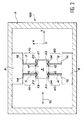
- les figures 2 et 3 représentent des modes de réalisation de l'invention ;
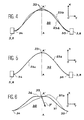
- la figure 4 représente des lignes axiales d'une poutre d'élongation ;
- en l'absence de contrainte exercée en son centre par un élément de suspension,
- en présence d'une traction exercée en son centre par un élément de suspension, cette traction étant exercée dans la direction où elle tend à réduire l'importance du creux,
- la figure 5 représente des lignes axiales d'une poutre d'élongation ;
- en l'absence de contrainte exercée en son centre par un élément de suspension,
- en présence d'une poussée exercée en son centre sur le fond du creux par un élément de suspension ;
- la figure 6 représente une forme particulièrement avantageuse de ligne axiale d'une poutre d'élongation et des déformations de cette forme sous l'effet de contrainte ;
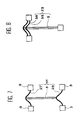
- les figures 7 et 8 montrent des exemples d'utilisation de poutres d'élongation pour constituer des moyens de suspension améliorés ;
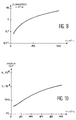
- les figures 9 et 10 sont des courbes illustrant des modes de calcul des moyens d'élongation.
- FIGS. 1A to 1D already commented on represent examples of an embodiment of a mechanical structure comprising a movable mass according to the prior art;
- Figures 2 and 3 show embodiments of the invention;
- FIG. 4 represents axial lines of an elongation beam;
- in the absence of stress exerted in its center by a suspension element,
- in the presence of a traction exerted in its center by a suspension element, this traction being exerted in the direction in which it tends to reduce the importance of the hollow,
- Figure 5 shows axial lines of an elongation beam;
- in the absence of stress exerted in its center by a suspension element,
- in the presence of a thrust exerted in its center on the bottom of the hollow by a suspension element;
- FIG. 6 represents a particularly advantageous form of axial line of an elongation beam and deformations of this form under the effect of stress;
- Figures 7 and 8 show examples of the use of extension beams to form improved suspension means;
- Figures 9 and 10 are curves illustrating methods of calculating the elongation means.
Dans les figures, les éléments ayant mêmes fonctions que les éléments déjà décrits dans les figures 1 portent le même numéro de référence que dans les figures 1.In the figures, the elements having the same functions that the elements already described in the Figures 1 have the same reference number as in Figures 1.
Les figures 2 et 3 représentent une structure mécanique comportant une masse mobile 3 comme celle décrite par exemple en relation avec la figure 1B. Les exemples de structures mécaniques 100 représentés sur la figure 2 se différencient de l'exemple de l'art antérieur représenté sur la figure 1B par l'ajout de moyens d'élongation 23, 25 dans l'élément d'ancrage 9 et 24, 26 dans l'élément d'ancrage 8. Par contre, dans la figure 3 les moyens d'élongation 23, 25 et 24, 26 sont incorporés au niveau de la masse mobile 3. Les moyens d'élongation 23 à 26 sont incorporés dans des évidements 19, 21 de l'ancrage 9 et 20, 22 de l'ancrage 8 pour la figure 2. Ces mêmes évidements 19 à 22 sont pratiqués au niveau de la masse mobile 3 sur la figure 3. Les moyens d'élongation des figures 2 et 3 se présentent sous la forme d'une petite poutre 23 à 26. Chacune de ces poutres a deux extrémités et les extrémités de chacune de ces poutres sont en liaison mécanique avec les bords des évidements 19 à 22 dans lesquels elles sont respectivement logées. Les déformations de ces poutres 23-26 dans le plan XOY du mouvement de la masse mobile 3 permettent un déplacement de la masse mobile sans augmentation de la contrainte présente au niveau des poutres 4 à 7 et donc permettent d'avoir un mouvement de la masse mobile 3 linéaire en fonction de l'excitation. Dans les cas représentés figures 2 et 3, les moyens d'élongation 23 à 26 sont placés à l'extrémité des éléments de suspension 4 à 7 se trouvant soit au niveau des ancrages 8 et 9 (figure 2) soit au niveau de la masse mobile 3 (figure 3). Du point de vue du calcul de la longueur et de la section des moyens d'élongation 23 à 26 il revient au même que ce moyen soit fixé dans un évidement au niveau de l'une des masses d'ancrage 8 ou 9, ou au niveau de la masse mobile 3. En règle générale, des considérations additionnelles relatives aux dimensions de la masse mobile 3 ou des points d'ancrage 8 et 9 conduiront à installer ces moyens d'élongation 23 à 26 au niveau des masses d'ancrage.Figures 2 and 3 show a structure mechanical with a moving mass 3 like that described for example in relation to FIG. 1B. The examples of mechanical structures 100 represented on figure 2 differ from the example of art shown in Figure 1B by adding elongation means 23, 25 in the anchoring element 9 and 24, 26 in the anchoring element 8. On the other hand, in Figure 3 the elongation means 23, 25 and 24, 26 are incorporated at the moving mass 3. The extension means 23 to 26 are incorporated in recesses 19, 21 of the anchor 9 and 20, 22 of the anchor 8 for FIG. 2. These same recesses 19 to 22 are practiced at the moving mass 3 in the figure 3. The elongation means of Figures 2 and 3 are are in the form of a small beam 23 to 26. Each of these beams has two ends and the ends of each of these beams are connected mechanical with the edges of the recesses 19 to 22 in which they are respectively housed. The deformations of these beams 23-26 in the XOY plane of the movement of the moving mass 3 allow a displacement of the moving mass without increasing the stress present at beams 4 to 7 and therefore allow movement of the moving mass 3 linear as a function of excitation. In the cases shown in Figures 2 and 3, the elongation means 23 to 26 are placed at the end of the elements of suspension 4 to 7 either at the level of anchors 8 and 9 (figure 2) or at ground level mobile 3 (figure 3). From the point of view of calculating the length and section of the elongation means 23 to 26 it is the same that this plea be fixed in a recess at one of the anchoring masses 8 or 9, or at the moving mass 3. As a rule general, additional considerations relating to the dimensions of moving mass 3 or points anchor 8 and 9 will lead to installing these means elongation 23 to 26 at the anchor masses.
Sur les figures 2 et 3, l'élément de suspension 5 et le moyen d'élongation 23 forment ensemble un moyen de suspension amélioré 50. De même, les éléments 7-25, 4-24, et 6-26, forment ensemble respectivement des moyens de suspension améliorés 70, 40 et 60. Les extrémités des moyens de suspension améliorés 40, 50, 60 à 70 sont constituées comme suit.In FIGS. 2 and 3, the suspension element 5 and the elongation means 23 together form a means suspension system 50. Similarly, the elements 7-25, 4-24, and 6-26, together form respectively improved suspension means 70, 40 and 60. The ends of the improved suspension means 40, 50, 60 to 70 are constituted as follows.
Sur la figure 2, les extrémités du moyen de suspension amélioré 50 sont constituées d'une part par l'extrémité 13 de l'élément de suspension 5 raccordée à la masse mobile 3 et par les extrémités du moyen d'élongation 23 raccordées à l'évidement 19. Il en est de même pour les trois autres moyens de suspension améliorés 40, 60 et 70, l'une des extrémités de chacun de ces moyens de suspension améliorés est constituée par une extrémité d'un élément de suspension par exemple 17 pour l'élément de suspension 7, 11 pour l'élément de suspension 4 et 15 pour l'élément de suspension 6. L'autre extrémité du moyen de suspension améliorée 70 est constituée par les extrémités du moyen d'élongation 25. Il en va de même pour les moyens de suspension améliorée 40 et 60.In Figure 2, the ends of the means of improved suspension 50 consist on the one hand by the end 13 of the suspension element 5 connected to the moving mass 3 and by the ends of the means 23 connected to the recess 19. It is the same for the other three means of suspension improved 40, 60 and 70, one end of each of these improved suspension means is constituted by one end of a suspension element by example 17 for the suspension element 7, 11 for the suspension element 4 and 15 for the suspension 6. The other end of the suspension means improved 70 is formed by the ends of the means elongation 25. The same applies to the means of improved suspension 40 and 60.
La forme et les déformations de moyens d'élongation selon l'invention seront maintenant décrits plus en détail en liaison avec les figures 4 à 6.The form and deformations of means according to the invention will now be described in more detail in conjunction with Figures 4 to 6.
Ces figures représentent toutes des lignes axiales de poutres d'élongation par exemple 23, 25 telles que représentées figure 2.These figures all represent lines axial of elongation beams for example 23, 25 as shown in Figure 2.
Par ligne axiale, on entend une ligne située à égale distance de bords latéraux de la poutre. La poutre ayant une forme longiligne, la forme de la ligne axiale est représentative des courbures de cette poutre.By axial line is meant a line located equal distance from the side edges of the beam. The beam having a slender shape, the shape of the line axial is representative of the curvatures of this beam.
Ces lignes sont représentées dans le plan XOY de déplacement de la masse mobile 3 tel que représenté par des axes figures 2 et 3. Ces mêmes axes sont représentés sur les figures 4 à 6. La référence 23 est attribuée à chacune des courbes représentées sur les figures 4 à 6 indiquant ainsi, qu'il s'agit par exemple de la ligne axiale de la poutre 23, logée dans l'évidement 19 de la figure 2.These lines are represented in the XOY plan displacement of the moving mass 3 as shown by axes Figures 2 and 3. These same axes are shown in Figures 4 to 6. Reference 23 is attributed to each of the curves represented on the Figures 4 to 6 thus indicating, that it is for example of the axial line of the beam 23, housed in the recess 19 in FIG. 2.
Chacune des courbes délimite un creux 32 tourné dans cet exemple vers les X négatifs. Chaque courbe 23 présente un axe de symétrie AA' parallèle à l'axe OX, le fond 33 du creux 32 se trouvant sur cet axe de symétrie en sorte qu'une tangente à la courbe 23 au fond du creux est parallèle à l'axe OY de déplacement de la masse oscillante 3. La tangente aux extrémités 34, 35 de la poutre 23 est, dans cet exemple, parallèle à la direction OY. L'angle de cette tangente avec la direction OY peut être compris entre 0 et 45°.Each of the curves delimits a hollow 32 turned in this example to the negative X's. Each curve 23 has an axis of symmetry AA ′ parallel to the axis OX, the bottom 33 of the hollow 32 lying on this axis of symmetry so that a tangent to curve 23 at bottom of the trough is parallel to the axis OY of displacement of the oscillating mass 3. The tangent at the ends 34, 35 of the beam 23 is, in this example, parallel to the direction OY. The angle of this tangent with the direction OY can be between 0 and 45 °.
Il y a donc un point d'inflexion de la courbe 23 entre le fond du creux 33 et chacun des points extrêmes 34, 35. La figure 4 représente une première ligne axiale 23a qui est la forme de la poutre 23 en l'absence de force exercée selon une direction perpendiculaire à la tangente au fond 33 du creux 32.So there is an inflection point in the curve 23 between the bottom of the hollow 33 and each of the points extremes 34, 35. FIG. 4 represents a first axial line 23a which is the shape of the beam 23 in the absence of force exerted in one direction perpendicular to the tangent to the bottom 33 of the hollow 32.
Elle représente également une seconde ligne axiale 23b qui est la forme de la courbe 23 lorsqu'une traction est effectuée sur le fond 33 du creux 32 par la poutre 5 dans la direction de l'axe X et orientée, dans le cas représenté sur la figure 4, vers les X négatifs. Le creux de la courbe 23b est moins profond que celui de la courbe 23a.It also represents a second line axial 23b which is the shape of curve 23 when a traction is carried out on the bottom 33 of the hollow 32 by the beam 5 in the direction of the X axis and oriented, in the case shown in Figure 4, towards the X negative. The trough of curve 23b is shallower than that of curve 23a.
La différence de profondeur est nettement perceptible, par contre les points extrêmes 34, 35 qui sont les points d'ancrage, étant les mêmes, la courbe 23b est plus renflée que la courbe 23a entre le point 33 et chacun des points 34, 35. Lorsqu'une traction dans le sens de la flèche est effectuée sur le fond 33 du creux, la poutre 33 travaille en compression..The difference in depth is clearly noticeable, on the other hand the extreme points 34, 35 which are the anchor points, being the same, the curve 23b is more swollen than the curve 23a between the point 33 and each of points 34, 35. When a pull in the direction of the arrow is performed on the bottom 33 from the hollow, the beam 33 works in compression.
Sur la figure 5, on a représenté également deux lignes axiales 23a et 23c. La courbe 23a représente comme sur la figure 4 la forme de la poutre 23 lorsqu'aucune force n'est exercée sur le fond du creux. La courbe 23c représente cette même forme lorsqu'une force égale et de sens opposé à celle ayant provoqué la déformation faisant passer de la courbe 23a à la courbe 23b est exercée sur le fond 33 du creux. Cette force est sur la figure 5, orientée vers les X positifs.In FIG. 5, two are also shown axial lines 23a and 23c. Curve 23a represents as in Figure 4 the shape of the beam 23 when no force is exerted on the bottom of the hollow. Curve 23c represents this same shape when a equal force and opposite direction to that which caused the deformation passing from curve 23a to curve 23b is exerted on the bottom 33 of the hollow. This strength is in Figure 5, oriented towards positive X's.
On voit sur la figure 5 que les courbes 23a et 23c sont pratiquement confondues l'une avec l'autre au point de ne former ensemble qu'un seul trait épais. Lorsqu'une force tendant à approfondir le creux est exercée sur le fond du creux, comme représenté figure 5, la poutre travaille en traction.It can be seen in FIG. 5 that the curves 23a and 23c are practically confused with each other at not to form together a single thick line. When a force tending to deepen the trough is exerted on the bottom of the hollow, as shown in figure 5, the beam works in traction.
Le fait qu'une force suffisante pour déformer sensiblement la poutre, lorsque la poutre travaille en compression, est insuffisante pour faire apparaítre une déformation perceptible lorsque cette même poutre travaille en traction résulte de la différence de raideur apparente de la poutre 23 lorsqu'elle travaille en compression et lorsqu'elle travaille en traction.The fact that enough force to distort substantially the beam, when the beam works in compression, is insufficient to reveal a noticeable deformation when this same beam works in traction results from the difference of apparent stiffness of beam 23 when working in compression and when working in traction.
Il en résulte que si une accélération ou un choc est exercée sur la structure se traduisant par une force ayant une composante dirigée vers les X négatifs, cette force n'entraínera pas ou peu de déformation de la suspension. Il en résulte qu'un capteur équipé d'une telle structure sera insensible aux accélérations se traduisant par des forces exercées dans le sens des X positifs.As a result, if an acceleration or shock is exerted on the structure resulting in a force with a component directed towards negative X, this force will cause little or no deformation of suspension. As a result, a sensor equipped with a such structure will be insensitive to accelerations translating by forces exerted in the direction of X positive.
Si comme représenté sur les figures 2 ou 3, la masse oscillante 3 est suspendue par au moins deux éléments 4, 5 symétriques l'un de l'autre par rapport à une direction parallèle à l'axe OY et que les poutres d'élongation 23, 24 correspondantes sont de plus symétriques l'une de l'autre par rapport à ce même axe, alors une force exercée selon la direction OX, quel que soit son sens, s'exercera sur l'une des poutres 23 ou 24 pour la faire travailler en traction.If as shown in Figures 2 or 3, the oscillating mass 3 is suspended by at least two elements 4, 5 symmetrical to each other with respect to a direction parallel to the OY axis and that the beams elongation 23, 24 corresponding are more symmetrical to each other with respect to this same axis, then a force exerted in the direction OX, whatever either its meaning, will be exerted on one of the beams 23 or 24 to make it work in traction.
Ainsi, dans le mode de réalisation représenté figure 2 ou 3, les poutres 23-26 travaillent en compression lorsque la masse mobile 3 se déplace dans la direction OY. Deux des poutres 23-26 travaillent en traction lorsque une accélération selon OX est imprimée à la structure 100.Thus, in the embodiment shown Figure 2 or 3, beams 23-26 work in compression when the moving mass 3 moves in the direction OY. Two of beams 23-26 work in traction when an acceleration according to OX is printed to structure 100.
Une forme avantageuse de poutre d'élongation sera maintenant commentée en liaison avec la figure 6. Cette figure représente une ligne axiale 37 d'une poutre d'élongation telle que par exemple la poutre 23. Cette poutre a les mêmes caractéristiques, en particulier de dissymétrie de réponse à la traction ou la compression que celles décrites en liaison avec la description de la ligne axiale 23a. Elle a la particularité d'avoir un fond de creux 32 plat. Cela se traduit sur la ligne axiale 37 par le fait qu'elle comporte un segment central de droite 36. Les extrémités 34, 35 sont symétriques l'une de l'autre par rapport à la ligne axiale de la poutre par exemple 5.An advantageous form of extension beam will now be discussed in connection with FIG. 6. This figure represents an axial line 37 of a elongation beam such as for example beam 23. This beam has the same characteristics, in particular tensile response asymmetry or compression than those described in conjunction with the description of the axial line 23a. She has the particularity of having a flat bottom of hollow 32. This is translated on the axial line 37 by the fact that it has a central segment on the right 36. The ends 34, 35 are symmetrical to each other by relative to the axial line of the beam for example 5.
Cette structure présente l'avantage que le
segment 36 peut pivoter autour d'un axe OZ
perpendiculaire au plan XOY au point 33 de croisement
de la ligne axiale de la poutre 23 et de son axe de
symétrie AA' pratiquement librement. Ce pivotement
autour du point est illustré par la courbe 37b qui
illustre la forme de la ligne axiale lorsque la poutre
est sollicitée par la masse mobile lorsque cette masse
a quitté sa position de repos. Cette sollicitation est
représentée par une flèche
Sur les figures 2 et 3 les moyens d'élongation 23, 26 ont chacun la forme représentée par la courbe 23a, figure 4 ou avantageusement 37, figure 6. Sur ces figures le moyen d'élongation 23-26 est soit sur les ancrages 8,9 (figure 2) soit sur la masse mobile 3 (figure 3).In Figures 2 and 3 the elongation means 23, 26 each have the shape represented by the curve 23a, Figure 4 or advantageously 37, Figure 6. On these figures the means of elongation 23-26 is either on the anchors 8.9 (figure 2) or on the moving mass 3 (figure 3).
D'autres exemples d'utilisation de moyens d'élongation ayant la forme décrite en relation avec la figure 4 ou la figure 6 seront maintenant décrit en référence aux figures 7 et 8.Other examples of the use of resources of elongation having the form described in relation to the Figure 4 or Figure 6 will now be described in reference to Figures 7 and 8.
Pour des raisons de simplification sur les figures 7 et 8, seul l'élément de suspension améliorée 50 a été représenté sous une forme modifiée portant les références 51, 53 sur chacune des figures 7, 8 respectivement. Il convient de comprendre que le moyen de suspension amélioré 40 est construit de la même façon ou de façon symétrique par rapport à un axe parallèle à OY. De même, si la suspension comporte quatre moyens de suspension améliorés, les moyens 60 et 70 sont construits de la même façon ou de façon symétrique l'une de l'autre par rapport à un axe parallèle à OY.For reasons of simplification on the Figures 7 and 8, only the improved suspension element 50 has been shown in modified form bearing the references 51, 53 in each of FIGS. 7, 8 respectively. It should be understood that the means improved suspension 40 is built the same way or symmetrically about an axis parallel to OY. Similarly, if the suspension includes four improved suspension means, means 60 and 70 are constructed in the same way or so symmetrical to each other with respect to an axis parallel to OY.
Sur les figures 7 et 8, les références 3 et 9 représentant respectivement la masse oscillante et l'ancrage ont été portés sur des carrés symbolisant ces éléments.In Figures 7 and 8, references 3 and 9 respectively representing the oscillating mass and the anchor were worn on squares symbolizing these elements.
Il convient cependant de noter que ces références 3, 9, et donc les éléments correspondants pourraient être permutés sans que le fonctionnement de la structure 100 en soit modifié.However, it should be noted that these references 3, 9, and therefore the corresponding elements could be swapped without the operation of structure 100 is modified.
Sur la figure 7, le moyen de suspension amélioré 51 est constitué de la poutre de suspension 5, et de deux poutres d'élongation 27, 28. Les deux extrémités de la poutre 27 sont connectées mécaniquement à l'ancrage 9. Les deux extrémités de la poutre 28 sont connectées mécaniquement à la masse oscillante 3. Dans le mode de réalisation représenté figure 7, les creux des poutres d'élongation 27, 28 sont tournés d'un même côté et la poutre de suspension 5 a l'une de ses extrémités raccordées au fond du creux de la poutre d'élongation 27 et l'autre extrémité raccordée au sommet de la bosse formant l'envers du creux de la poutre d'élongation. Un autre mode de réalisation est de tourner le creux de la poutre d'élongation de l'autre côté.In FIG. 7, the suspension means improved 51 consists of the suspension beam 5, and two elongation beams 27, 28. Both ends of beam 27 are connected mechanically at anchor 9. The two ends of the beam 28 are mechanically connected to ground oscillating 3. In the embodiment shown Figure 7, the hollows of the elongation beams 27, 28 are turned on the same side and the suspension beam 5 has one of its ends connected to the bottom of the hollow of the extension beam 27 and the other end connected to the top of the hump forming the back of the hollow of the extension beam. Another mode of realization is to turn the hollow of the beam on the other side.
Sur la figure 8, le moyen de suspension amélioré 53 est constitué de la poutre de suspension 5, et de plusieurs poutres d'élongation dont les extrémités sont connectées par exemple à l'ancrage. Dans l'exemple représenté figure 8, il y a deux poutres 38, 39. Le point milieu de l'une des poutres d'élongation est connecté à une extrémité de la poutre 5 de suspension. Le point milieu de la seconde poutre 39 d'élongation et éventuellement de poutres additionnelles est connecté entre les deux extrémités de la poutre de suspension 5.In FIG. 8, the suspension means improved 53 consists of the suspension beam 5, and several elongation beams, the ends are connected for example to the anchor. In the example shown in Figure 8, there are two beams 38, 39. The midpoint of one of the beams extension is connected to one end of the beam 5 suspension. The midpoint of the second beam 39 of elongation and possibly of beams additional is connected between the two ends of the suspension beam 5.
Compte tenu de ce qui a déjà été dit plus haut, sur les possibles symétries et similitudes, il convient de comprendre que de telles configurations avec plusieurs poutres d'élongation à une extrémité peuvent être utilisés comme dans les cas décrits en relation avec les figures 2, 3, et 7, un ensemble de plusieurs poutres remplaçant l'une au moins des poutres uniques 23-30. Ainsi, un premier groupe de poutres telles que les poutres 38, 39 représentées à titre d'exemple figure 8 peut remplacer chacune des poutres d'élongation uniques telles que 27, représentées figures 7. Un moyen de suspension amélioré tel que le moyen 51 peut également comporter un second groupe de poutres, ces groupes ayant par exemple même forme et même orientation de creux que la poutre 28 représenté figure 7.Given what has already been said above, on possible symmetries and similarities, it should to understand that such configurations with multiple extension beams at one end can be used as in the cases described in relation with Figures 2, 3, and 7, a set of several beams replacing at least one of the single beams 23-30. So, a first group of beams such as beams 38, 39 shown by way of example figure 8 can replace each of the beams unique elongations such as 27, shown figures 7. An improved suspension means such as medium 51 can also include a second group of beams, these groups having for example the same shape and same hollow orientation as the beam 28 shown figure 7.
Dans tous les exemples de réalisation présentés sur les figures 2, 3 et 7, 8, les moyens d'élongation 23-28 et 38, 39 ont en commun d'être déformables compte tenu des forces qui leur sont appliquées, dans le plan XOY défini d'une part, par la direction des mouvements de la masse mobile 3 et, d'autre part, par la direction des éléments de suspension 4, 5, 6, 7. Les moyens d'élongation 23-28 et 37-39 permettent de relâcher les contraintes induites dans les éléments de suspension comme l'élément 4 sans perturber les caractéristiques du mouvement de la masse mobile et ceci pour des déplacements beaucoup plus importants que ceux autorisés sans ce moyen. Le moyen d'élongation 23-28 et 36, 38, 39 n'introduit pas de mode parasite proche de la résonance du système. Il ne perturbe quasiment pas la fréquence propre du mouvement : le degré de liberté supplémentaire introduit par le moyen d'élongation est efficace en n'ajoutant que très peu de souplesse dans le système complet. Il faut comprendre que des moyens de relâchement de contrainte sous forme de moyens d'élongation 23-28 et 37-39 doivent être ajoutés à chacune des poutres subissant une contrainte lors du déplacement d'une masse mobile du système complet. Les non linéarités en sont nettement affaiblies et la limite d'amplitude du mouvement de la masse mobile permettant de conserver la linéarité est alors repoussée. L'invention permet d'augmenter l'amplitude du mouvement de la masse mobile de plusieurs ordres de grandeurs. La géométrie de la ou des poutres qui constitue le moyen d'élongation peut être diverse comme par exemple de section rectangulaire ou ronde constante sur toute la longueur de la poutre, la dissymétrie de raideur étant introduite comme dans les exemples commentés en liaison avec les figures 2 à 8 par la forme de la ligne axiale. Comme expliqué plus haut, cette dissymétrie de raideur peut également être obtenue par des variations de la forme de la section droite du moyen d'élongation entre sa première et sa seconde extrémités. Les moyens d'élongation selon l'invention ont en outre l'avantage d'être insensibles aux accélérations perpendiculaires au mouvement de la masse oscillante.In all the exemplary embodiments presented in Figures 2, 3 and 7, 8, the elongation means 23-28 and 38, 39 have in common to be deformable account given the forces applied to them, in the plan XOY defined on the one hand, by the direction of movements moving mass 3 and, on the other hand, by the direction suspension elements 4, 5, 6, 7. The means 23-28 and 37-39 allow to release the induced stresses in the suspension elements like element 4 without disturbing the characteristics of the movement of the moving mass and this for much larger displacements than those allowed without this means. The extension means 23-28 and 36, 38, 39 does not introduce parasitic mode close to the resonance of the system. It hardly disturbs the natural frequency of the movement: the degree of freedom additional introduced by the elongation means is effective by adding very little flexibility in the complete system. You have to understand that means of stress relief in the form of means 23-28 and 37-39 should be added to each of the beams undergoing stress during displacement of a moving mass of the complete system. The non linearities are significantly weakened and the range of motion of the moving mass allowing to keep the linearity is then pushed back. The invention makes it possible to increase the amplitude of the movement of the moving mass of several orders of sizes. The geometry of the beam (s) which constitutes the means of elongation can be diverse as for example of constant rectangular or round section over the entire length of the beam, the asymmetry of stiffness being introduced as in the examples commented in conjunction with Figures 2 to 8 by the shape of the axial line. As explained above, this stiffness asymmetry can also be obtained by variations of the shape of the section right of the elongation means between its first and its second ends. The means of elongation according to the invention also have the advantage of being insensitive at accelerations perpendicular to the movement of the oscillating mass.
La démarche à suivre pour dimensionner le moyen d'élongation est expliquée maintenant.The procedure to follow to size the means elongation is explained now.
La raideur élastique du moyen d'élongation est calculée de façon à ce que la déformation du moyen d'élongation au cours du mouvement de la masse mobile évite l'apparition d'une trop forte variation de raideur dans l'élément ou les éléments de suspension amélioré(s) sous l'effet de la contrainte appliquée audit élément de suspension. Tout d'abord on évalue l'effet de la contrainte induite dans chacun des éléments de suspension qui soutiennent la masse mobile lors du mouvement d'oscillation de cette masse et lorsqu'aucun moyen d'élongation n'est utilisé. Cette contrainte est facilement calculée en appliquant les relations classiques de la résistance des matériaux et dépend de la géométrie des éléments de suspension.The elastic stiffness of the elongation means is calculated so that the deformation of the means of elongation during movement of the moving mass prevents the appearance of too great a variation in stiffness in the suspension element (s) improved under the effect of the applied stress said suspension element. First we assess the effect of the stress induced in each of suspension elements that support the moving mass during the oscillating movement of this mass and when no means of elongation is used. This stress is easily calculated by applying the classical relationships of material resistance and depends on the geometry of the suspension elements.
La figure 9 représente dans le cas d'une poutre
de section rectangulaire et de type encastré-encastré
constituant un élément de suspension pour une masse
mobile, oscillant suivant l'axe Y, l'évolution de la
déformation de la poutre constituant l'élément de
suspension suivant l'axe X en fonction de l'amplitude
d'oscillation suivant Y. L'amplitude de l'oscillation
de la masse mobile est portée en abscisse alors qu'en
ordonnée on a l'élongation du moyen de suspension
exprimé en µm. A partir de la valeur de la déformation,
et dans le cas d'une poutre indéformable suivant sa
longueur (direction X) et ne possédant pas de moyen
d'élongation, la figure 10 représente l'évolution de la
raideur équivalente de la poutre. On a porté en
abscisse l'amplitude de l'oscillation et en ordonnée,
la raideur exprimée en Kg/s2. On détermine la raideur
du moyen d'élongation de façon à ce que sa déformation
soit d'une dimension comparable à la valeur de
l'élongation telle que déterminée et représentée au
moyen de la courbe représentée figure 9. Une fois
encore ces calculs de la valeur de la raideur
s'appuient sur les lois classiques de la résistance des
matériaux. Le dimensionnement du moyen d'élongation
doit également prendre en compte que la déformation de
ce moyen doit rester telle qu'elle ne provoque pas une
variation importante de la raideur de celui-ci. Il
s'agit là d'une limitation de la capacité du moyen
d'élongation à favoriser des amplitudes d'oscillation
de la masse mobile encore plus importantes. Dans le cas
particulier tel que représenté figure 1A ou figure 1B
où la suspension en l'absence du moyen d'élongation est
constitué par une ou plusieurs poutres de type
encastré-encastré l'équation du mouvement de la masse
mobile peut s'exprimer sous la forme générale bien
connue :
Dans cette équation Y représente l'élongation
du mouvement de la masse mobile, t représente le temps,
λ représente un coefficient d'amortissement, ω0
représente la fréquence de résonance et α et β sont des
coefficients de non linéarité. F0 représente la force
appliquée. Les coefficients α et β sont choisis tels
que αYmax est très inférieur à ω0 2 et βY2 max est très
inférieur à ω0 2. De façon connue, un mouvement ayant
cette équation devient instable lorsque l'amplitude du
mouvement dépasse la valeur limite donnée par la
formulation suivante :
Dans cette équation Yℓ est la valeur limite de l'amplitude d'oscillation et Q est égal à ω0 / 2λ. Q représente le facteur de qualité mécanique de la structure. Si l'on veut rendre linéaire l'équation du mouvement de la masse mobile, il faut ajouter un moyen d'élongation tel que les coefficients α et β de l'équation vont être nuls ou très faibles. Le coefficient α peut être considéré comme négligeable, on va donc chercher à minimiser le coefficient β. Il convient que le coefficient β du moyen de suspension améliorée constitué d'une part, par l'élément de suspension et, d'autre part par le moyen d'élongation soit aussi petit que possible. Pour les exemples représentés sur l'une des figures 2, 3 et 7, 8, dans lesquels les poutres sont de section rectangulaire et de type encastré-encastré, la valeur du coefficient β de la poutre équivalente formée par le moyen d'élongation et le moyen de suspension est proportionnelle à WH / L3. W,H et L représentent respectivement les largeur, hauteur et longueur de la poutre équivalente qui suspend la masse mobile. Quand plusieurs poutres soutiennent la masse mobile on applique les règles classiques de superposition pour déterminer la poutre équivalente. Dans les exemples de réalisation tels que représentés sur les figures 2, 3 et 7, 8, le moyen d'élongation se présente sous la forme d'une poutre unique ayant ses deux extrémités reliées à un élément mécanique qui peut être considéré comme fixe par rapport au mouvement de la masse mobile. Cet élément mécanique 23 à 28 ou 36, 38, 39 est lui-même relié au support fixe du système ou à la masse mobile. Lorsque l'élément de suspension est constitué, par exemple, par une poutre principale dont la longueur est de l'ordre du mm, cette poutre ne permettant une oscillation de l'élément mobile que de quelques µm lorsque le facteur de qualité Q est élevé (supérieur à quelques centaines), le moyen d'élongation utilisé par exemple à une extrémité au moins de chacune des poutres principales peut présenter une section équivalente à la section des poutres principales. Une longueur de quelques centaines de µm du moyen d'élongation permet d'obtenir des oscillations de quelques dizaines de µm, soit une amélioration de l'amplitude d'oscillation de plusieurs ordres de grandeur.In this equation Yℓ is the limit value of the amplitude of oscillation and Q is equal to ω 0 / 2λ. Q represents the mechanical quality factor of the structure. If we want to make the equation of motion of the moving mass linear, we need to add a means of elongation such that the coefficients α and β of the equation will be zero or very small. The coefficient α can be considered negligible, so we will try to minimize the coefficient β. The coefficient β of the improved suspension means constituted on the one hand, by the suspension element and, on the other hand by the elongation means should be as small as possible. For the examples represented in one of FIGS. 2, 3 and 7, 8, in which the beams are of rectangular section and of recessed-recessed type, the value of the coefficient β of the equivalent beam formed by the elongation means and the means of suspension is proportional to WH / L 3 . W, H and L respectively represent the width, height and length of the equivalent beam which suspends the mobile mass. When several beams support the mobile mass we apply the classic rules of superposition to determine the equivalent beam. In the exemplary embodiments as shown in Figures 2, 3 and 7, 8, the elongation means is in the form of a single beam having its two ends connected to a mechanical element which can be considered to be fixed by relation to the movement of the moving mass. This mechanical element 23 to 28 or 36, 38, 39 is itself connected to the fixed support of the system or to the movable mass. When the suspension element is constituted, for example, by a main beam whose length is of the order of mm, this beam only allowing an oscillation of the movable element of a few μm when the quality factor Q is high (greater than a few hundred), the elongation means used for example at at least one end of each of the main beams may have a section equivalent to the section of the main beams. A length of a few hundred μm of the elongation means makes it possible to obtain oscillations of a few tens of μm, that is to say an improvement in the amplitude of oscillation by several orders of magnitude.
Il en résulte qu'un capteur, par exemple un accélérateur, un gyromètre, un pressostat incorporant une structure mécanique 100 selon l'invention présentera une sensibilité et une discrimination améliorées.As a result, a sensor, for example a accelerator, gyrometer, pressure switch incorporating a mechanical structure 100 according to the invention will exhibit sensitivity and discrimination improved.
Claims (12)
Applications Claiming Priority (2)
| Application Number | Priority Date | Filing Date | Title |
|---|---|---|---|
| FR0005487 | 2000-04-28 | ||
| FR0005487A FR2808264B1 (en) | 2000-04-28 | 2000-04-28 | MICRO-MACHINED MECHANICAL STRUCTURE AND DEVICE INCORPORATING THE STRUCTURE |
Publications (3)
| Publication Number | Publication Date |
|---|---|
| EP1152245A2 true EP1152245A2 (en) | 2001-11-07 |
| EP1152245A3 EP1152245A3 (en) | 2005-01-05 |
| EP1152245B1 EP1152245B1 (en) | 2010-08-11 |
Family
ID=8849729
Family Applications (1)
| Application Number | Title | Priority Date | Filing Date |
|---|---|---|---|
| EP01401050A Expired - Lifetime EP1152245B1 (en) | 2000-04-28 | 2001-04-25 | Micromachined mechanical structure and device using the same |
Country Status (6)
| Country | Link |
|---|---|
| US (1) | US6546801B2 (en) |
| EP (1) | EP1152245B1 (en) |
| JP (1) | JP2001337099A (en) |
| CA (1) | CA2344728A1 (en) |
| DE (1) | DE60142760D1 (en) |
| FR (1) | FR2808264B1 (en) |
Cited By (2)
| Publication number | Priority date | Publication date | Assignee | Title |
|---|---|---|---|---|
| WO2002093180A1 (en) * | 2001-05-15 | 2002-11-21 | Honeywell International Inc. | Accelerometer strain relief structure |
| CN101798053A (en) * | 2010-04-15 | 2010-08-11 | 西安电子科技大学 | Fully compliant penta-stable mechanism and implementation method thereof |
Families Citing this family (26)
| Publication number | Priority date | Publication date | Assignee | Title |
|---|---|---|---|---|
| FR2834055B1 (en) * | 2001-12-20 | 2004-02-13 | Thales Sa | MICRO-MACHINED INERTIAL SENSOR FOR MEASURING ROTATIONAL MOVEMENTS |
| FR2838423B1 (en) * | 2002-04-12 | 2005-06-24 | Thales Sa | METHOD FOR MANUFACTURING A MICROSTRUCTURE COMPRISING A VACUUM CAVITY AND CORRESPONDING MICROSTRUCTURE |
| US20040140415A1 (en) * | 2003-01-21 | 2004-07-22 | Nikon Corporation | Vibration-attenuation devices having low lateral stiffness, and apparatus comprising same |
| US6912902B2 (en) * | 2003-03-26 | 2005-07-05 | Honeywell International Inc. | Bending beam accelerometer with differential capacitive pickoff |
| US7542188B2 (en) * | 2004-01-20 | 2009-06-02 | National University Of Singapore | Optical scanning using vibratory diffraction gratings |
| EP1735591B1 (en) * | 2004-04-14 | 2014-01-22 | Analog Devices, Inc. | Inertial sensor with a linear array of sensor elements |
| US7187486B2 (en) * | 2004-04-27 | 2007-03-06 | Intel Corporation | Electromechanical drives adapted to provide two degrees of mobility |
| US7180650B2 (en) * | 2005-03-29 | 2007-02-20 | Intel Corporation | Electromechanical drives adapted to provide three degrees of mobility |
| US7802475B2 (en) * | 2006-10-13 | 2010-09-28 | Seiko Epson Corporation | Acceleration sensor |
| EP2327960B1 (en) | 2008-08-18 | 2019-10-09 | Hitachi, Ltd. | Micro electro mechanical system |
| JP5130237B2 (en) * | 2009-02-20 | 2013-01-30 | パナソニック株式会社 | Semiconductor physical quantity sensor |
| JP5206709B2 (en) * | 2009-03-18 | 2013-06-12 | 株式会社豊田中央研究所 | Device having a movable body |
| DE102009002701B4 (en) * | 2009-04-28 | 2018-01-18 | Hanking Electronics, Ltd. | Micromechanical sensor |
| GB2470398B (en) * | 2009-05-21 | 2014-03-19 | Ge Infrastructure Sensing Inc | A resonant sensor for measuring the pressure of a fluid |
| JP5083635B2 (en) * | 2009-11-12 | 2012-11-28 | 三菱電機株式会社 | Acceleration sensor |
| JP4905574B2 (en) * | 2010-03-25 | 2012-03-28 | 株式会社豊田中央研究所 | Laminated structure with moving parts |
| FR2964652B1 (en) | 2010-09-13 | 2015-05-15 | Commissariat Energie Atomique | RESONANT DEVICE WITH PIEZORESISTIVE DETECTION AND RESONATOR RELATED ELASTICALLY TO THE SUPPORT OF THE DEVICE, AND METHOD OF MANUFACTURING THE SAME |
| US20140144232A1 (en) * | 2012-11-28 | 2014-05-29 | Yizhen Lin | Spring for microelectromechanical systems (mems) device |
| US9638524B2 (en) * | 2012-11-30 | 2017-05-02 | Robert Bosch Gmbh | Chip level sensor with multiple degrees of freedom |
| DE102014215038A1 (en) * | 2014-07-31 | 2016-02-04 | Robert Bosch Gmbh | Micromechanical sensor and method for producing a micromechanical sensor |
| US10345330B2 (en) | 2015-09-25 | 2019-07-09 | Apple Inc. | Mechanical low pass filter for motion sensors |
| US10324105B2 (en) * | 2015-09-25 | 2019-06-18 | Apple Inc. | Mechanical low pass filter for motion sensors |
| US10196259B2 (en) | 2015-12-30 | 2019-02-05 | Mems Drive, Inc. | MEMS actuator structures resistant to shock |
| FR3074793B1 (en) * | 2017-12-12 | 2021-07-16 | Commissariat Energie Atomique | MICROELECTROMECHANICAL AND / OR NANOELECTROMECHANICAL DEVICE OFFERING INCREASED ROBUSTNESS |
| JP6964102B2 (en) * | 2019-01-16 | 2021-11-10 | 株式会社鷺宮製作所 | MEMS beam structure and MEMS vibration power generation element |
| US11044572B2 (en) | 2019-08-29 | 2021-06-22 | Digital Factory Technologies, Inc. | System and method for clustering end users to select and deliver a notification to mobile device |
Citations (2)
| Publication number | Priority date | Publication date | Assignee | Title |
|---|---|---|---|---|
| US5025346A (en) * | 1989-02-17 | 1991-06-18 | Regents Of The University Of California | Laterally driven resonant microstructures |
| US5650568A (en) * | 1993-02-10 | 1997-07-22 | The Charles Stark Draper Laboratory, Inc. | Gimballed vibrating wheel gyroscope having strain relief features |
Family Cites Families (9)
| Publication number | Priority date | Publication date | Assignee | Title |
|---|---|---|---|---|
| SU493770A1 (en) | 1972-02-07 | 1975-11-28 | Каунасский Политехнический Институт | Device for measuring the amplitude of oscillations of a rotating elastic system during the transition through resonance |
| US5144184A (en) * | 1990-01-26 | 1992-09-01 | The Charles Stark Draper Laboratory, Inc. | Micromechanical device with a trimmable resonant frequency structure and method of trimming same |
| DE4126107C2 (en) * | 1991-08-07 | 1993-12-16 | Bosch Gmbh Robert | Accelerometer and manufacturing method |
| US5220835A (en) * | 1991-09-12 | 1993-06-22 | Ford Motor Company | Torsion beam accelerometer |
| EP0765464B1 (en) | 1994-06-16 | 2003-05-14 | Robert Bosch Gmbh | Angular rate sensor |
| US5583291A (en) * | 1995-07-31 | 1996-12-10 | Motorola, Inc. | Micromechanical anchor structure |
| JPH11337571A (en) * | 1998-05-27 | 1999-12-10 | Japan Aviation Electronics Ind Ltd | Inertia sensor |
| US5920012A (en) | 1998-06-16 | 1999-07-06 | Boeing North American | Micromechanical inertial sensor |
| JP2000046862A (en) * | 1998-07-28 | 2000-02-18 | Matsushita Electric Works Ltd | Semiconductor acceleration sensor |
-
2000
- 2000-04-28 FR FR0005487A patent/FR2808264B1/en not_active Expired - Fee Related
-
2001
- 2001-04-19 CA CA002344728A patent/CA2344728A1/en not_active Abandoned
- 2001-04-23 US US09/839,134 patent/US6546801B2/en not_active Expired - Lifetime
- 2001-04-25 EP EP01401050A patent/EP1152245B1/en not_active Expired - Lifetime
- 2001-04-25 DE DE60142760T patent/DE60142760D1/en not_active Expired - Lifetime
- 2001-04-27 JP JP2001133110A patent/JP2001337099A/en active Pending
Patent Citations (2)
| Publication number | Priority date | Publication date | Assignee | Title |
|---|---|---|---|---|
| US5025346A (en) * | 1989-02-17 | 1991-06-18 | Regents Of The University Of California | Laterally driven resonant microstructures |
| US5650568A (en) * | 1993-02-10 | 1997-07-22 | The Charles Stark Draper Laboratory, Inc. | Gimballed vibrating wheel gyroscope having strain relief features |
Cited By (4)
| Publication number | Priority date | Publication date | Assignee | Title |
|---|---|---|---|---|
| WO2002093180A1 (en) * | 2001-05-15 | 2002-11-21 | Honeywell International Inc. | Accelerometer strain relief structure |
| US6634231B2 (en) | 2001-05-15 | 2003-10-21 | Honeywell International, Inc. | Accelerometer strain isolator |
| CN101798053A (en) * | 2010-04-15 | 2010-08-11 | 西安电子科技大学 | Fully compliant penta-stable mechanism and implementation method thereof |
| CN101798053B (en) * | 2010-04-15 | 2011-07-27 | 西安电子科技大学 | Fully compliant penta-stable mechanism and implementation method thereof |
Also Published As
| Publication number | Publication date |
|---|---|
| EP1152245A3 (en) | 2005-01-05 |
| FR2808264B1 (en) | 2002-06-07 |
| JP2001337099A (en) | 2001-12-07 |
| EP1152245B1 (en) | 2010-08-11 |
| DE60142760D1 (en) | 2010-09-23 |
| FR2808264A1 (en) | 2001-11-02 |
| US20020011117A1 (en) | 2002-01-31 |
| CA2344728A1 (en) | 2001-10-28 |
| US6546801B2 (en) | 2003-04-15 |
Similar Documents
| Publication | Publication Date | Title |
|---|---|---|
| EP1152245B1 (en) | Micromachined mechanical structure and device using the same | |
| EP2791048B1 (en) | Mechanical connection forming a pivot for mems and nems mechanical structures | |
| EP1626282B1 (en) | Microgyroscope with frequency detection | |
| EP2617130B1 (en) | Resonant piezoresistive detector having a resonator connected elastically to the supporting member of the detector, and process for manufacturing said detector | |
| EP1515119B1 (en) | Micro fabricated gyroscope with a double tuning fork | |
| EP0373040B1 (en) | Force-frequency transducer with vibrating beams and its use in a vibrating accelerometer | |
| EP2520940B1 (en) | Inertial unit with a plurality of detection axes | |
| FR2917731A1 (en) | DEVICE RESONANT TO PIEZORESISTIVE DETECTION REALIZED IN SURFACE TECHNOLOGIES | |
| EP2449344B1 (en) | Micro-machined gyroscope with detection in the plane of the machined plate | |
| EP1558896B1 (en) | Micro-machined gyro rate sensor with detection in the machined plate plane | |
| FR2964651A1 (en) | SUSPENDED BEAM DEVICE AND MEANS FOR THE PIEZORESISTIVE DETECTION OF THE DISPLACEMENT THEREOF, AND METHOD FOR MANUFACTURING THE DEVICE | |
| FR2924422A1 (en) | SUSPENDED PIEZORESISTIVE STRAIN GAUGE DETECTION DEVICE COMPRISING A STRAIN AMPLIFICATION CELL. | |
| EP3394564B1 (en) | System for suspending a mobile mass comprising means for linking the mobile mass with optimised linearity | |
| EP3766829B1 (en) | Mechanical link for mems and nems device for measuring a pressure variation and device comprising such a mechanical link | |
| WO2004053503A1 (en) | Vibrating beam accelerometer | |
| FR3098809A1 (en) | Mechanical link for MEMS and NEMS mechanical structure, and MEMS and NEMS structure including such mechanical link | |
| EP3722253B1 (en) | Out-of-plane hinge for micromechanical and/or nanomechanical structure with reduced sensitivity to internal constraints | |
| EP1515118B1 (en) | Micro-machined vibrating gyroscope with in-plane detection | |
| FR2789171A1 (en) | MONOLITHIC STRUCTURE OF A VIBRATING GYROMETER | |
| EP3498661A1 (en) | Microelectromechanical and/or nanoelectromechanical device providing increased sturdiness | |
| FR3000050A1 (en) | MICROELECTROMECHANICAL DEVICE HAVING AT LEAST TWO DEFORMABLE ELEMENTS OF DIFFERENT DIMENSIONS | |
| EP4148432B1 (en) | Microelectromechanical resonant sensor with decoupling mass interposed betweeen resonator and proofmass | |
| CA2673442C (en) | Guiding blade for a proof mass and micromachined electromechanical system using such blade | |
| WO2020008157A2 (en) | Compact high-performance resonant micromechanical gyrometer | |
| FR2821433A1 (en) | Monolithic planar accelerometer with a symmetric arrangement of two vibrating bodies supported by articulations and vibrating beams whose vibration is linked to acceleration of the structure to which the accelerometer is attached |
Legal Events
| Date | Code | Title | Description |
|---|---|---|---|
| PUAI | Public reference made under article 153(3) epc to a published international application that has entered the european phase |
Free format text: ORIGINAL CODE: 0009012 |
|
| AK | Designated contracting states |
Kind code of ref document: A2 Designated state(s): AT BE CH CY DE DK ES FI FR GB GR IE IT LI LU MC NL PT SE TR |
|
| AX | Request for extension of the european patent |
Free format text: AL;LT;LV;MK;RO;SI |
|
| PUAL | Search report despatched |
Free format text: ORIGINAL CODE: 0009013 |
|
| AK | Designated contracting states |
Kind code of ref document: A3 Designated state(s): AT BE CH CY DE DK ES FI FR GB GR IE IT LI LU MC NL PT SE TR |
|
| AX | Request for extension of the european patent |
Extension state: AL LT LV MK RO SI |
|
| RIC1 | Information provided on ipc code assigned before grant |
Ipc: 7G 01C 19/56 B Ipc: 7B 81B 3/00 B Ipc: 7G 01P 15/00 A |
|
| 17P | Request for examination filed |
Effective date: 20050326 |
|
| AKX | Designation fees paid |
Designated state(s): CH DE FI FR GB IT LI |
|
| RAP1 | Party data changed (applicant data changed or rights of an application transferred) |
Owner name: THALES Owner name: COMMISSARIAT A L'ENERGIE ATOMIQUE |
|
| RAP1 | Party data changed (applicant data changed or rights of an application transferred) |
Owner name: THALES Owner name: COMMISSARIAT A L'ENERGIE ATOMIQUE |
|
| RAP1 | Party data changed (applicant data changed or rights of an application transferred) |
Owner name: THALES Owner name: COMMISSARIAT A L'ENERGIE ATOMIQUE |
|
| 17Q | First examination report despatched |
Effective date: 20080602 |
|
| GRAP | Despatch of communication of intention to grant a patent |
Free format text: ORIGINAL CODE: EPIDOSNIGR1 |
|
| GRAC | Information related to communication of intention to grant a patent modified |
Free format text: ORIGINAL CODE: EPIDOSCIGR1 |
|
| GRAJ | Information related to disapproval of communication of intention to grant by the applicant or resumption of examination proceedings by the epo deleted |
Free format text: ORIGINAL CODE: EPIDOSDIGR1 |
|
| GRAP | Despatch of communication of intention to grant a patent |
Free format text: ORIGINAL CODE: EPIDOSNIGR1 |
|
| RAP1 | Party data changed (applicant data changed or rights of an application transferred) |
Owner name: THALES Owner name: COMMISSARIAT A L'ENERGIE ATOMIQUE ET AUX ENERGIES |
|
| GRAS | Grant fee paid |
Free format text: ORIGINAL CODE: EPIDOSNIGR3 |
|
| GRAA | (expected) grant |
Free format text: ORIGINAL CODE: 0009210 |
|
| AK | Designated contracting states |
Kind code of ref document: B1 Designated state(s): CH DE FI FR GB IT LI |
|
| REG | Reference to a national code |
Ref country code: GB Ref legal event code: FG4D Free format text: NOT ENGLISH |
|
| REG | Reference to a national code |
Ref country code: CH Ref legal event code: EP |
|
| REF | Corresponds to: |
Ref document number: 60142760 Country of ref document: DE Date of ref document: 20100923 Kind code of ref document: P |
|
| PG25 | Lapsed in a contracting state [announced via postgrant information from national office to epo] |
Ref country code: FI Free format text: LAPSE BECAUSE OF FAILURE TO SUBMIT A TRANSLATION OF THE DESCRIPTION OR TO PAY THE FEE WITHIN THE PRESCRIBED TIME-LIMIT Effective date: 20100811 |
|
| PLBE | No opposition filed within time limit |
Free format text: ORIGINAL CODE: 0009261 |
|
| STAA | Information on the status of an ep patent application or granted ep patent |
Free format text: STATUS: NO OPPOSITION FILED WITHIN TIME LIMIT |
|
| 26N | No opposition filed |
Effective date: 20110512 |
|
| REG | Reference to a national code |
Ref country code: DE Ref legal event code: R097 Ref document number: 60142760 Country of ref document: DE Effective date: 20110512 |
|
| REG | Reference to a national code |
Ref country code: CH Ref legal event code: PL |
|
| PG25 | Lapsed in a contracting state [announced via postgrant information from national office to epo] |
Ref country code: LI Free format text: LAPSE BECAUSE OF NON-PAYMENT OF DUE FEES Effective date: 20110430 Ref country code: CH Free format text: LAPSE BECAUSE OF NON-PAYMENT OF DUE FEES Effective date: 20110430 |
|
| PGFP | Annual fee paid to national office [announced via postgrant information from national office to epo] |
Ref country code: IT Payment date: 20120423 Year of fee payment: 12 |
|
| PG25 | Lapsed in a contracting state [announced via postgrant information from national office to epo] |
Ref country code: IT Free format text: LAPSE BECAUSE OF NON-PAYMENT OF DUE FEES Effective date: 20130425 |
|
| REG | Reference to a national code |
Ref country code: FR Ref legal event code: PLFP Year of fee payment: 16 |
|
| REG | Reference to a national code |
Ref country code: DE Ref legal event code: R081 Ref document number: 60142760 Country of ref document: DE Owner name: COMMISSARIAT A L'ENERGIE ATOMIQUE ET AUX ENERG, FR Free format text: FORMER OWNERS: COMMISSARIAT A L'ENERGIE ATOMIQUE ET AUX ENERGIES ALTERNATIVES, PARIS, FR; THALES, PARIS, FR |
|
| REG | Reference to a national code |
Ref country code: GB Ref legal event code: 732E Free format text: REGISTERED BETWEEN 20160616 AND 20160622 |
|
| REG | Reference to a national code |
Ref country code: FR Ref legal event code: TP Owner name: COMMISSARIAT A L'ENERGIE ATOMIQUE ET AUX ENERG, FR Effective date: 20160718 |
|
| REG | Reference to a national code |
Ref country code: FR Ref legal event code: PLFP Year of fee payment: 17 |
|
| PGFP | Annual fee paid to national office [announced via postgrant information from national office to epo] |
Ref country code: GB Payment date: 20170420 Year of fee payment: 17 |
|
| REG | Reference to a national code |
Ref country code: FR Ref legal event code: PLFP Year of fee payment: 18 |
|
| GBPC | Gb: european patent ceased through non-payment of renewal fee |
Effective date: 20180425 |
|
| PG25 | Lapsed in a contracting state [announced via postgrant information from national office to epo] |
Ref country code: GB Free format text: LAPSE BECAUSE OF NON-PAYMENT OF DUE FEES Effective date: 20180425 |
|
| PGFP | Annual fee paid to national office [announced via postgrant information from national office to epo] |
Ref country code: FR Payment date: 20200430 Year of fee payment: 20 Ref country code: DE Payment date: 20200408 Year of fee payment: 20 |
|
| REG | Reference to a national code |
Ref country code: DE Ref legal event code: R071 Ref document number: 60142760 Country of ref document: DE |