EP1151861B1 - Printing press with perfecting station - Google Patents
Printing press with perfecting station Download PDFInfo
- Publication number
- EP1151861B1 EP1151861B1 EP01650052A EP01650052A EP1151861B1 EP 1151861 B1 EP1151861 B1 EP 1151861B1 EP 01650052 A EP01650052 A EP 01650052A EP 01650052 A EP01650052 A EP 01650052A EP 1151861 B1 EP1151861 B1 EP 1151861B1
- Authority
- EP
- European Patent Office
- Prior art keywords
- sheet
- printing
- drum
- printing press
- ink fixing
- Prior art date
- Legal status (The legal status is an assumption and is not a legal conclusion. Google has not performed a legal analysis and makes no representation as to the accuracy of the status listed.)
- Expired - Lifetime
Links
Images







Classifications
-
- B—PERFORMING OPERATIONS; TRANSPORTING
- B41—PRINTING; LINING MACHINES; TYPEWRITERS; STAMPS
- B41F—PRINTING MACHINES OR PRESSES
- B41F7/00—Rotary lithographic machines
- B41F7/02—Rotary lithographic machines for offset printing
- B41F7/025—Multicolour printing or perfecting on sheets or on one or more webs, in one printing unit
-
- B—PERFORMING OPERATIONS; TRANSPORTING
- B41—PRINTING; LINING MACHINES; TYPEWRITERS; STAMPS
- B41F—PRINTING MACHINES OR PRESSES
- B41F13/00—Common details of rotary presses or machines
- B41F13/54—Auxiliary folding, cutting, collecting or depositing of sheets or webs
- B41F13/70—Depositing
-
- B—PERFORMING OPERATIONS; TRANSPORTING
- B41—PRINTING; LINING MACHINES; TYPEWRITERS; STAMPS
- B41F—PRINTING MACHINES OR PRESSES
- B41F23/00—Devices for treating the surfaces of sheets, webs, or other articles in connection with printing
- B41F23/04—Devices for treating the surfaces of sheets, webs, or other articles in connection with printing by heat drying, by cooling, by applying powders
- B41F23/044—Drying sheets, e.g. between two printing stations
-
- B—PERFORMING OPERATIONS; TRANSPORTING
- B41—PRINTING; LINING MACHINES; TYPEWRITERS; STAMPS
- B41F—PRINTING MACHINES OR PRESSES
- B41F7/00—Rotary lithographic machines
- B41F7/02—Rotary lithographic machines for offset printing
- B41F7/10—Rotary lithographic machines for offset printing using one impression cylinder co-operating with several transfer cylinders for printing on sheets or webs, e.g. satellite-printing units
Definitions
- the present invention relates to a printing press having a perfecting station wherein the perfecting station includes a multi-purpose drum for printing and transferring a printed substrate.
- the present invention also relates to a printing press having a printing unit which is easily accessible in order to perform necessary maintenance procedures.
- Printing presses that are capable of printing an image on both sides of a sheet are well known in the art.
- One way in which two sided printing has been achieved was by running a sheet between two blanket cylinders which simultaneously print the front and reverse side of the sheet as it passes there between. It is also known to send a sheet through a printing press in which the first side of a sheet is printed and then reversing the sheet and sending it through to print on the reverse side of the sheet. Printing on the reverse or backside of a sheet is referred to as perfecting.
- Prior art two sided printing machines are shown in U.S. Patent Nos. 4,471,695, 4,621,576 and DE-C-271645.
- Linear type printing presses that print a sheet at various stations along a conveyer are also known. Such presses are able to perfect a sheet by adding a perfecting printing station to the line either before or after the front side printing stations.
- these types of linear presses consume a considerable amount of floor space and are not practical for small shops. Set up and maintenance of these presses is also fairly time consuming.
- U.S. Patent No. 4,967,660 discloses a central impression drum type printing press that is capable of printing on both sides of a sheet.
- the discharge cylinder both assists in transporting the sheet from the main impression cylinder to outside the press and acts as an impression cylinder for the perfecting of the sheet.
- the discharge cylinder works in cooperation with a sprocket and endless chain, the chain carrying a plurality of mechanical grippers. The grippers are carried by the chain rotate over the discharge cylinder and capture the sheet from the central impression cylinder.
- the grippers then carry the sheet over the discharge drum to a point where it passes between the discharge drum and blanket cylinder. After perfecting is completed, the printed sheet is carried by the chain driven grippers until it is deposited in a finished sheet collection point. While the surface of the discharge drum is used as an impression cylinder, a separate mechanism including the grippers, endless chain and sprocket, is required in order to transport and discharge the paper. In addition, in order to accommodate the chains and mechanical grippers, a notch must be formed in the discharge cylinder. Due to this complicated construction, maintenance of the perfecting unit could be rather involved. Removal of the discharge cylinder in order to clear a jam or clean the impression cylinder surface would require removal of the chains and/or sprocket resulting in a time consuming operation.
- the sheet after being printed on the first side proceeds directly to the perfecting station without processing by a dryer or other type of ink fixing unit. Accordingly, the image on the first side must air dry sufficiently before it contacts the exit drum to prevent smearing of the image. Therefore, the speed at which sheets are printed is limited by the drying time of the ink.
- Printing presses are also known for their need for frequent maintenance which may include removing sheets after a jam is detected. Maintenance includes cleaning the various blanket cylinders and other interior areas of the press in order to ensure a quality output. While performing servicing, it is important that the press be down for as short of time possible in order for the maximum efficiency of the press to be realized.
- printing presses having a central impression drum and a plurality of individual printing units spaced thereabout access to various parts of the press becomes an issue. Since this type of press is a rather compact unit it is often difficult to get to the various areas in which maintenance needs to be formed. For example, in printing presses in which a dryer is installed between two of the printing stations, the dryer must often be removed in order to gain access to the interior portions of the press for maintenance.
- Removal of the dryer can require unfastening a variety of fastening hardware and then physically lifting the dryer off of the unit and placing it somewhere where it will be safely stored. Once maintenance is completed, the unit must then be placed back into position and refastened to the machine. Such an operation of simply removing the dryer to gain access can be rather involved and take a significant amount of time.
- a printing press that is capable of printing on the front and reverse side of a sheet wherein the exit or discharge cylinder includes a sheet attachment mechanism formed thereon and the exit cylinder also functions as an impression cylinder for a perfecting printing unit. It would also be desirable to provide a printing press which is easily maintainable and provides quick and easy access to all areas such that scheduled and unscheduled maintenance may be quickly performed thereby reducing the downtime of the press.
- the ink fixing device may be positioned between a first side printing station and the perfecting station in order to fix the ink on the first side of a substrate prior to perfecting.
- a printing press including a printing unit.
- the printing unit includes a frame and a central impression drum rotatably supported on the frame adapted to transport a sheet.
- a plurality of first side printing stations is circumferentially spaced about the central impression drum and in communication therewith.
- the first side printing stations are adapted to impart an image to a first side of the sheet being transported by the central impression drum.
- a perfecting printing station is disposed at a point about the central impression drum sequentially after the plurality of first side printing stations for imparting an image to a second side of the sheet.
- the perfecting printing station includes a multi-purpose drum having a first sheet retainer attached thereto for securing the sheet to the multi-purpose drum, the multi-purpose drum forming an impression cylinder and being in rolling communication with an image transfer cylinder for printing an image on the second side of the sheet.
- An ink fixing unit is disposed between the first side printing stations and the perfecting station.
- the ink fixing unit fixes the image on the first side of the sheet prior to the image being imparted on the second side of the sheet by the perfecting station.
- the printing unit of the printing press of the invention includes an exit station from which a printed sheet exits the printing unit.
- a delivery table is positioned adjacent the exit station for receiving and transporting the printed sheet.
- the delivery table is translatable between an extended position wherein the delivery table is in operative communication with an exit station of the printing unit and a retracted position wherein when the delivery table is in the retracted position, operator access between the printing unit and the output table is provided.
- the present invention includes a printing press having the ability to print on the front and reverse side of a substrate such as a sheet or envelope without requiring the substrate to be unduly manipulated.
- the printing press of the present invention is particularly suited for the high speed printing of envelopes. The printing on both sides is achieved in a single pass through the press thereby eliminating the need to re-feed the work through the press.
- the present invention also fixes the ink on the first side prior to perfecting the sheet.
- the printing press of the present invention is therefore, capable of high speed and high quality output.
- printing presses typically require frequent scheduled and unscheduled maintenance. Scheduled maintenance may involve cleaning the blanket cylinders and impressions cylinder as well as other components. Unscheduled maintenance may include clearing jams and mis-feeds that occur.
- the present invention permits the press to be quickly and easily serviced thereby reducing any maintenance related downtime.
- Printing press 10 generally includes a printing unit 12 that may transfer an image to a front and reverse sides of a substrate 11 by an offset printing process. The finished work is transported to a delivery table 14 where it may be collected for further processing.
- a printing unit 12 that may transfer an image to a front and reverse sides of a substrate 11 by an offset printing process.
- the finished work is transported to a delivery table 14 where it may be collected for further processing.
- front and reverse side of a sheet are used only to refer to a first and second side of a sheet and not any particular orientation of the surface of a sheet or printable substrate.
- printing unit 12 preferably includes a material in-feed mechanism 19 that transfers sheets of material 11 to be printed into a printing chamber 16.
- In-feed mechanism 19 may include a pair of spaced endless chains 15 including upstanding pushers 15a and an in-feed drum 13 for transporting the material from an upper feeder 17a or a lower feeder 17b to a printing chamber 16 where the printing occurs.
- a housing 18 at least partially surrounds printing chamber 16.
- Printing chamber 16 includes a central impression drum 20 rotatably secured to a frame 22.
- Central impression drum 20 is operatively connected to a drive mechanism 21 that continuously rotates the central impression drum 20 during the printing operation.
- a resilient blanket material 20a substantially surrounds a printing surface of central impression drum 20 to provide the proper backing for a sheet upon printing.
- Central impression drum 20 may further include a plurality of mechanical grippers 34 spaced about its circumference. Grippers 34 selectively engage a leading edge of the sheet off of in-feed drum 13 and secure the sheet to the central impression drum as it rotates through printing unit 12.
- Front side printing stations 24 are disposed within printing chamber 16.
- four first side printing stations 24 may be employed to provide a four color press capability.
- Front side printing stations 24 cooperate with central impression drum 20 to transfer an image to the front side of sheet 11 as it passes there between.
- Each front side printing station 24 includes a plate cylinder 26 and blanket cylinder 32 and ink fountain mechanism 30. Vibration dampening rollers may also be included as is well known in the art.
- Plate cylinder 26 supports a printing plate 28, and ink is transferred from ink fountain mechanism 30 by various inking rollers 31 onto printing plate 28.
- Printing plate 28 transfers an image onto blanket cylinder 32 which then imparts the image onto sheet 11 as it travels between blanket cylinder 32 and central impression drum 20. This operation is typical for an offset printing process.
- Printing stations 24 may each impart a different color and/or image to the sheet thereby providing a wide range of colors which may be created as well known in the art.
- the printing unit as heretofore described including the four first side printing stations may be similarly constructed as a type well known in the art marketed by assignee, Halm Industries Co., Inc., under the name Envelopemaster, Series EM 4000.
- printing unit 10 further includes a perfecting station 36 for printing on the reverse side of a sheet prior to the sheet exiting printing chamber 16.
- Printing on the reverse side of a sheet is achieved without a complicated mechanism for turning over the sheet or having to send the sheet through a second printing process further down the line.
- Perfecting station 36 is disposed about central impression drum 20 at a point sequentially after the front side printing stations. Therefore, the printing of the front side of the sheet will be completed prior to the image being printed on the reverse side of the sheet.
- Perfecting station 36 includes a multi-purpose drum 38 that performs the function of both a sheet transferring exit drum and an impression drum for providing an image to the reverse side of the sheet.
- Perfecting station 36 may also include an ink fountain mechanism 37 having a variety of inking rollers and dampening rollers and a blanket cylinder 40 and a plate cylinder 42 of the type used in the first side printing stations 24. It is also within the contemplation of the present invention to provide a perfecting station having a plurality of ink fountain mechanisms and blanket and plate cylinder combinations disposed in operative communication with multi-purpose drum 38 in order to print multiple images or colors on the reverse side of the sheet.
- multi-purpose drum 38 In its role as an impression drum, multi-purpose drum 38 functions in cooperation with blanket cylinder 40 and plate cylinder 42 in an offset process to print the reverse side of the sheet. Accordingly, sheet 11 passing between multi-purpose drum 38 and its corresponding blanket cylinder 40 receives an image on the reverse side of the sheet. If a plurality of blanket and plate cylinders are provided, multiple colors or images may be transferred to the sheet.
- multi-purpose drum 38 preferably includes a substantially continuous peripheral surface 39 in order to provide the necessary support to the sheet while it is being printed.
- a resilient blanket material 39a similar to the material found on the various blanket cylinders 32,40 and central impression drum 20 substantially covers peripheral surface 39.
- Multi-purpose drum 38 is rotatably secured within printing unit 12 such that it is in rolling contact with central impression drum 20.
- multi-purpose drum 38 includes a row of spaced pockets 41 extending along a portion of the width of multi-purpose drum 38. Pockets 41 are spaced such that they align with the mechanical grippers 34 protruding from central impression drum 38 thereby providing clearance for grippers 34.
- a sheet 11 traveling on central impression drum 20 is picked up by multi-purpose drum 38 and is transferred past blanket cylinder 40 in order to print on the reverse side of the sheet.
- multi-purpose drum 38 includes a sheet retainer 44 that selectively secures a sheet to multi-purpose drum 38.
- grippers 34 release. At that point, sheet retainer 44 secures the leading edge of the sheet. The sheet is then attached to multi-purpose drum 38 and is transported off of central impression drum 20 toward perfecting blanket cylinder 40.
- Grippers 34 and sheet retainer 44 preferably engage the same leading edge portion of the sheet. Accordingly, the effective printing area of the sheet is not reduced by the use of two different sheet securement devices during the printing process.
- the printed first side of the sheet becomes positioned against the peripheral surface of multi-purpose drum 38.
- the unprinted reverse side of the sheet is then positioned for engagement with the image carrying perfecting blanket cylinder 40.
- multi-purpose drum 38 is twice the diameter of the corresponding blanket cylinder 40. Accordingly, two sheets may be printed upon one revolution of multi-purpose drum 38 to facilitate high output of printed material.
- the multi-purpose drum may include two sets of pockets 41 and a pair of sheet retainers 44 substantially diametrically opposed from one another on multi-purpose drum 38. It is also within the contemplation of the present invention that multi-purpose drum 38 may have the same diameter as blanket cylinder 40. Alternatively, the multi-purpose drum 38 diameter may be 3, 4 times larger then the diameter of the blanket cylinder to process a plurality of sheets upon a single revolution.
- Sheet retainers 44 are attached to multi-purpose drum 38 and remain on drum 38 throughout the rotation thereof.
- sheet retainers 44 are preferably operated by vacuum.
- Each sheet retainer 44 includes a row of vacuum ports 46 integrally formed on drum 38 extending along drum 38 adjacent the row of gripper receiving pockets 41.
- Vacuum ports 46 are in fluid communication with a vacuum source 47 ( Figure 3) of a type well known in the art. Vacuum is selectively applied to ports 46 such that multi-purpose drum 38 can capture and release the sheet at the appropriate moments of the operation. Vacuum ports 46 are aligned such that they capture the leading edge of the sheet at the time when mechanical grippers 34 of central impression drum 20 release the sheet.
- grippers 34 release and vacuum is supplied to vacuum ports 46.
- the sheet is then transported by multi-purpose drum 38 over blanket cylinder 40 whereby the image is transferred to the reverse side of the sheet.
- the vacuum is then turned off to vacuum ports 46 in order to release the sheet.
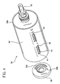
- Multi-purpose drum 38 preferably includes outer surface 39 and a central aperture 54 connected by an annular wall 56. Extending along a portion of the length of annular wall 56 is a pair of channels 53 in fluid communication with one of the two sets of vacuum ports 46. Channels 53 are open at one end of multi-purpose drum 38 and in communication with a valve 58. Central aperture 54 accommodates a transmission shaft 61 that drives drum 38. In order to selectively control vacuum to ports 46, valve 58 may be operatively disposed between the vacuum source and vacuum ports 46. Valve 58 preferably includes a disc 59 having an arcuate slot 59a and port 59b formed therein.
- Disc 59 may be urged against the end face of multi-purpose drum 38 by a biasing device 60 such as a helical spring.
- Slot 59a may be connected to a vacuum source and port 59b may be connected to atmosphere.
- Valve 58 remains stationary and multi-purpose drum 38 rotates relative thereto. Over a portion of the rotation of multi-purpose drum 38, slot 59a is also in communication with one of the pair of channels 53. Therefore, one set of vacuum ports 46 carries vacuum for securing the sheet to multi-purpose drum 38.
- the channel which was carrying vacuum comes into alignment with port 59b thereby releasing the vacuum and the sheet.
- Continued rotation of drum 38 brings the other channel 53 into alignment with slot 59a permitting the other set of vacuum ports to retain another sheet. Accordingly, the rotation of multi-purpose drum 38 results in vacuum ports 46 cyclically carrying vacuum followed by atmospheric pressure.
- an exit stripper assembly 63 ( Figure 8) may be positioned adjacent multi-purpose drum 38 to blow the sheet off drum 38 and ensure separation of the sheet from drum 38.
- Such exit strippers assemblies for providing an air blast at the appropriate moment are well known in the art.
- port 59b may be selectively operatively connected to a positive pressure generating device 49. Vacuum ports 46 would then carry pressurized air to blow the sheet off of multi-purpose drum 38 at the appropriate time. Therefore, vacuum ports 46 are in communication with a vacuum source over a first part of the rotation of multi-purpose drum 38 to retain the sheet and in communication with a positive pressure source over a second part of the rotation of multi-purpose drum 38 to release the sheet.
- sheet retainer 44 may include mechanical grippers attached to multi-purpose drum 38. Such grippers would selectively open and close to capture and release a sheet at the appropriate times. Sheet retainer 44 may also be in the form of an electrostatic charge imparted to the multi-purpose drum. The multi-purpose drum or a portion thereof could be charged to attract a sheet to pull the sheet away from the central impression drum. After the perfecting is completed, a reverse charge could be applied to the multi-purpose drum to release the sheet therefrom.
- Multi-purpose drum 38 of the present invention by way of the attached sheet retainer 44, itself secures and transports the sheet through the perfecting stage and out of the printing chamber 16.
- no additional grippers or chains including the elements necessary to operate same are required in order to secure and transport the sheet through the perfecting operation.
- the present invention therefore, simplifies the perfecting process from both a manufacturing and maintenance standpoint.
- printing press 10 further preferably includes an ink fixing device 70 disposed on printing unit 12.
- Ink fixing device 70 fixes the ink deposited on the sheet to prevent smearing of the printed image. Once the ink is fixed, the printed surface may be contacted without corrupting the image.
- ink fixing device 70 may be disposed on printing unit 12 between perfecting station 36 and the immediately previous first side printing station 24. Therefore, after front side printing of the sheet 11 has been completed, the printed front side of the sheet is acted upon by ink fixing device 70 prior to the sheet engaging perfecting station 36. When a sheet passes through perfecting station 36 the printed front side is pressed against the blanket surface 39a of multi-purpose drum 38 as the reverse side is printed.
- ink fixing device 70 prior to the perfecting stage of the printing process permits high speed outputs on the order of 30,000 sheets per hour. Such speeds would not be achievable if the front side ink has to be air dried prior to perfecting.
- ink fixing device 70 preferably includes what is known in the art as a cold ultraviolet, (UV), dryer.
- UV cold ultraviolet
- the present invention also contemplates other types of ink fixing devices such as those which rely on infrared energy or hot air to dry the ink.
- the cold UV dryer works in association with UV sensitive inks. Generated UV energy reacts with the ink resulting in almost immediate curing of the ink through a process known as photopolymerization in a manner that is well known in the art.
- Ink fixing device 70 includes a lamp head 72 that generates the UV light required.
- One type of lamp head that has been found to be suitable is marketed by PRI of Dallas, Texas.
- Lamp head 72 cooperates with a cooling system 73 that circulates de-ionized water in front of a bulb 72a in lamp head 72 in order to filter out the unwanted infrared portion of the spectrum and allow the desirable UV wavelengths to pass onto the printed surface.
- the absorption of the infrared wavelengths heats the water but allows relatively "cool” radiant energy to pass onto the printed sheets.
- Ink fixing device 70 further includes a housing 77 which shields the lamp head and contains an air cooling plenum 72b which also assists in cooling lamp head 72.
- Service lines 71 including an exhaust hose 71a all exit from the side of housing 77. As shown in Figure 2, exhaust hose 71a is routed within the housing of printing unit 12 and exits out the top to facilitate connection to an on-site ventilation system if required.
- Cooling system 73 including a refrigeration unit 75 and heat exchanger 75a is provided for cooling the heated water circulated through ink fixing device 70.
- the refrigeration unit 75 may also be used for producing chilled fluid for use in printing unit 12 to cool the rollers of printing stations 24 and 36 such that only one refrigeration unit is necessary. It is known in the art to cool the rollers of the printing stations in order to maintain the ink at the optimal temperature. However, by using a single refrigeration unit to cool both the lamp head 72 and printing unit 12, significant reductions in printing press size and manufacturing costs can be achieved.
- Printing chamber 16 includes an opening 74 that exposes a portion of central impression drum 20 between the perfecting station 36 and the immediately proceeding front side printing station 24.
- Ink fixing device 70 has a front output portion 76 from which the UV energy emanates. Output portion 76 extends into opening 74 and is adjacent to central impression drum 20 such that the ink on the printed sheets travelling on drum 20 are exposed to the UV energy. Access to this portion of the printing chamber 16 is important in order to provide scheduled and unscheduled maintenance of multi-purpose drum 38 and the proceeding front side printing station 24. Therefore, in order to facilitative maintenance of ink fixing device 70 and the various elements disposed within printing chamber 16, ink fixing device 70 is preferably pivotally mounted to frame 22 of printing unit 12.
- Ink fixing device 70 is preferably pivotable between an operative position and a maintenance position. In the operative position, ink fixing device 70 covers printing unit opening 74 thereby placing the front output portion 76 adjacent central impression drum 20 so that fixing of the printed sheets may take place. During operation of printing press 10, it at times becomes necessary to remove ink fixing device 70 for maintenance purposes, such as for cleaning various components or clearing a jam. When access to this portion of printing unit 12 is required, ink fixing device 70 may be rotated to the maintenance position, exposing opening 74 into the printing unit. This may easily be achieved by rotating ink fixing device 70 to the maintenance position. Access is then made available to a portion of central impression drum 20 and the cylinders and drums of the adjacent front side printing station 24 and perfecting station 36.
- ink fixing device 70 While in the maintenance position, ink fixing device 70 is supported by frame 22, therefore, the press operator need not completely disconnect ink fixing device 70 from printing unit 12 and then reattach ink fixing device 70 after the servicing is completed. There is also no need to ensure that ink fixing device 70 is properly supported while off printing unit 12 so that control lines to ink fixing device 70 are not unduly strained or that the unit is not damaged. Accordingly, the time for servicing printing unit 12 is significantly reduced.
- the ink fixing device or dryer was typically bolted onto a printing unit and removal required unfastening a series of bolts or other fastening hardware.
- the ink fixing device would then have to be properly supported while the bolts were being removed and after the unit was separated from the printing unit. Reattaching the ink fixing device would require it to be supported while the fastening hardware was reattached.
- the present invention permits one operator to quickly and easily rotate ink fixing device 70 from the operative position to a maintenance position where access to a portion of printing chamber 16 is permitted. After maintenance is completed, ink fixing device 70 may easily be swung back to the operative position.
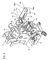
- Hinge 78 includes a bracket 80 that is fixedly secured to frame 22 of printing unit 12. Hinge 78 further includes an arm 82 that is fixedly attached to ink fixing device 70.
- Bracket 80 includes a mounting surface 84 that is fixedly securable to frame 22. Bracket mounting surface 84 is spaced by a rigid transition member 86 from a bracket pivot section 88.
- Pivot section 88 includes a pair of spaced flanges 90 having an aperture 92 extending there through. Flange apertures 92 are configured to receive a hollow sleeve 94 extending from a pivot end 96 of arm 82.
- Sleeve 94 includes a circumferentially extending slot 100 extending through the sleeve.
- Arm 82 further includes an elongate portion 98 upon which ink fixing device 70 is secured.
- sleeve 94 rotates within flange apertures 92.
- Slot 100 is disposed between flanges 90 thereby forming a passage through hinge 78 adjacent axis of rotation 101 to accommodate the service lines 71 such as cooling, control and power lines used for operating ink fixing device 70.
- Hinge 78 may include one or more detent positions to maintain ink fixing device 70 in a selected predetermined orientation.
- a detent is formed such that ink fixing device 70 is held in the maintenance position.
- the detent may be formed by cooperating spring-loaded balls 102 and divots 104 in the opposed contacting surfaces of the bracket and arm. It is understood that a variety of different mechanisms can be employed in order to provide the detent feature as is well known in the art.
- a lock-out 81 in the form of a mechanical switch may be employed adjacent hinge axis of rotation 101 such that it will be actuated by arm 82 upon moving ink fixing device 70 out of the operative position.
- Lock-out 81 is operatively connected to the printing press controls such that upon actuation of lock-out 81, printing press 10 including ink fixing device 70 would be shut down. Lock-out 81 may be positioned within the printing unit housing to prevent tampering.
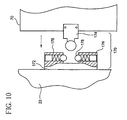
- Ink fixing device 70 may be held in the operative or closed position by a latch 170 that both securely retains ink fixing device 70 in the operative position and provides vertical support for its cantilevered end.
- latch 170 includes a U-shaped catch 172 attached to frame 22 and a strike 174 attached to the cantilevered end of ink fixing device 70.
- Catch 172 includes a pair of spaced arms 176 that each support a spring loaded projections 178.
- Strike 174 is sized to be inserted between arms 176 and engage biased projections 178 such that strike 174 is retained. Arms 176 also provide support against vertical loadings which may be imparted on ink fixing unit.
- latch 170 may be overcome by firmly pulling ink fixing device 70 toward its maintenance position.
- catch which has been found to provide suitable results is a ball-style tension catch P/N 1790A17 marketed by McMaster-Carr of New Jersey. It is also within the contemplation of the present invention that a variety of latches may be used in order to retain ink fixing unit in its operative position.
- ink fixing device may include a handle 180 secured thereto.
- Handle 180 is preferably formed so as to permit engagement by an operator from a variety of approaches. As shown in Figure 7, handle 180 has a side portion 180a that at one end is attached to ink fixing device 70 and extends upwardly above ink fixing device 70. Handle 180 then extends substantially parallel to a side of ink fixing device 70 and then over ink fixing device 70 form a top portion 180b. One end of top portion 180b is secured to the top of ink fixing device 70.
- Such a handle 180 permits ink fixing device 70 to be easily grabbed from either the top or side in order to accommodate an operator who may be positioned either to the side or in front of ink fixing device 70.
- printing unit 12 further includes an exit station 109 where printed sheets exit printing unit 12.
- Exit station 109 includes an output table 110 for receiving printed sheets exiting off of multi-purpose drum 38 and transporting them out of printing unit 12 to delivery table 14 where the printed material is collected.
- Output table 110 includes a conveying surface 112 for supporting and transporting the printed sheets to delivery table 14.
- output table 110 includes a first 114 and second 116 end each having a laterally extending roller 118a and 118b, respectively, rotatably supported on delivery table 110.
- Conveying surface 112 includes a plurality of spaced elastic bands 120, such as o-rings, that extend about rollers 118a and 118b and move in unison therewith.
- Rollers 118 and bands 120 extending thereabout are driven by a transmission element 122, such as a belt, extending between front roller 118a and a gear 124 that may be mechanically connected to the rotation of the multi-purpose drum 38. Accordingly, the rotational speed of multi-purpose drum 38 and conveying surface 112 are directly linked. This is advantageous since as the speed of multi-purpose drum 38 changes so does the discharge frequency of the sheets which must be accommodated by output table 110.
- the mechanical connection provides for a linear speed of conveying surface 112 so that printed sheets 11 will be transported without overlapping in order to prevent smearing of the reverse side printed image.
- Output table 110 may be connected to printing unit 12 such that it is both pivotally adjustable and easily removable from printing unit 12.
- output table may include a frame 126 having two spaced forks 128 adapted to engage pins 130 extending from frame 22. Pins 130 sit within forks 128 thereby providing a rotational coupling of the output table to the printing unit.
- a slotted attachment device 132 may be attached to one side of output table second end 116 to provide an adjustable attachment to frame 22.
- a second attachment device (not shown) may also be provided on the other side of output table second end 116. Accordingly, the angle of output table 110 can be adjusted to properly align with delivery table 14.
- Output table 110 may easily be removed by disconnecting the transmission element 122 and attachment device 132 and uncoupling forks 128 from pins 130. The ability to remove the output table permits access to the printing unit at a point adjacent to multi-purpose cylinder 36 and corresponding plate and blanket cylinders 42 and 40.
- Print sheets 11 are transported out of printing unit 12 onto delivery table 14 which is positioned adjacent output table second end 116.
- Delivery table 14 includes a conveyer 134 for moving printed sheets to a collection point where the sheets may be removed from printing press 10.
- Delivery tables of the prior art were typically fixed to the floor or some immovable base. Therefore, access to the exit station of the press adjacent the front end of the delivery table was obstructed by the table.
- the present invention overcomes the prior art limitations by permitting delivery table to translate.
- delivery table 14 may be translatable between an extended operative position adjacent exit station 109 for receiving sheets coming off of output table 110, and a retracted maintenance position for permitting access to printing unit 12. Accordingly, when an operator requires access to the section of printing unit 12 adjacent the area of output table 110 and perfecting unit, delivery table 14 may be moved into the retracted position such that there is room to stand directly in front of this portion of printing unit 12.
- the delivery table in order to permit delivery table 14 to be extended and retracted, the delivery table includes an elongate support 136 translatably fixed to a base 138.
- Base 138 may provide a housing for an electrical controller 139 operatively connected to ink fixing device 70 used to operate ink fixing device 70. This results in a significant reduction in floor space needed to accommodate printing press 10.
- Table elongate support 136 may include a plurality of longitudinally spaced rollers 140 extending outwardly therefrom.
- Delivery table further includes a translatable portion 142 longitudinally aligned with elongate support 136.
- Translatable portion 142 may include a pair of spaced downwardly extending side walls 144 extending along a length of translatable portion 142.
- Each side wall includes a track 146 extending therefrom configured to ride on rollers 140.
- This arrangement permits table translatable portion to move between the extended and retracted positions. It is also within the contemplation of the present invention that the linear translatable feature delivery table 14 may be accommodated by a variety of mechanical devices including linear bearings, slides and various roller configurations.
- rollers 140 may be rotatably fixed to translatable portion 142 and ride on a track or surface of the elongate support 136 ( Figure 2).
- Conveyer 134 is disposed on table translatable portion 142 and moves therewith.
- Table translatable portion 142 includes a front and rear wheel 148a and 148b rotatably secured to each end of thereof.
- a plurality of spaced fabric reinforced belts 150 (Figure 1) extend around table translatable portion 142 and in operative engagement with wheels 148a and 148b.
- Wheel 148a disposed at the back of translatable portion 142 is preferably operatively connected to a drive unit 152, such as a motor, to move belts 150 along the table.
- the moving belts 150 move along table 14 and carrying the printed sheets I 1 to the back end of the table where they engage a stacking ramp 152 and begin to form a stack of printed sheets. At this point, the sheets may be collected and removed from printing press 10.
- a locking device 154 may be employed.
- the locking device may include a threaded device supported by delivery table elongate support 136. Advancement of the thread causes the engagement of the working end 156 of the threaded device with the surface of the opposed translatable portion side walls 144.
- the height of delivery table 14 may be adjusted so that delivery table front end 14a, disposed adjacent to output table 110, may be positioned to receive sheets coming off of output table 110.
- elongate support 136 may be pivotally attached to base 138 at a first pivot point 158 and pivotally attached to a height adjuster 160 at a second pivot point 162 disposed closer to table front end then first pivot point 158.
- Height adjuster 160 may include a member 164 that may be selectively moved up or down thereby raising or lowering table leading end 14a. The movement may be provided by a jack screw device secured to base 138 wherein a turn of a wheel 166 causes member 164 to move up or down. The member 164 may then be held in the desired position when the proper height has been reached.
- the delivery table of the present invention permits the table to be moved out of the way to allow an operator to stand between the printing unit and the delivery table to aid in servicing the press. An operator may also easily adjust the delivery table 14 such that printed sheets exiting the printing unit 16 properly engage delivery table 14.
Landscapes
- Engineering & Computer Science (AREA)
- Mechanical Engineering (AREA)
- Rotary Presses (AREA)
- Feeding Of Articles By Means Other Than Belts Or Rollers (AREA)
- Soil Working Implements (AREA)
- Electrical Discharge Machining, Electrochemical Machining, And Combined Machining (AREA)
- Application Of Or Painting With Fluid Materials (AREA)
Abstract
Description
Claims (18)
- A printing press (10) comprising:a printing unit (12) including;a frame (22);a central impression drum (20) rotatably supported on said frame adapted to transport a sheet (11);a plurality of first side printing stations (24) circumferentially spaced about said central impression drum (20) and in communication therewith, said first side printing stations (24) adapted to impart an image to a first side of the sheet being transported by said central impression drum (20);a perfecting printing station (36) disposed about said central impression drum (20) sequentially after said plurality of first side printing stations (24) for imparting an image to a second side of the sheet (11), said perfecting printing station (36) including a multi-purpose drum (38), said multi-purpose drum (38) forming an impression cylinder and being in rolling communication with an image transfer cylinder (40) for printing an image on the second side of the sheet (11), characterised in that said multi-purpose drum (38) has a first sheet retainer (44) attached thereto for securing the sheet to said multi-purpose drum (38).
- The printing press (10) as claimed in Claim 1, wherein said first sheet retainer (44) is integral with said multi-purpose drum (38) and remains on said multi-purpose drum (38) throughout a rotation thereof.
- The printing press (10) as claimed in Claim 1, wherein said first sheet retainer (44) includes a plurality of first ports (46) spaced along a portion of a length of said multi-purpose drum (38) and being selectively in communication with a vacuum source for providing vacuum to said plurality of first ports (46).
- The printing press (10) as claimed in Claim 3, further including a positive pressure source and wherein said plurality of first ports (46) are selectively in communication with said positive pressure source such that the sheet may be separated from said multi-purpose drum (38).
- The printing press (10) as claimed in Claim 3, wherein said multi-purpose drum (38) includes a second sheet retainer diametrically opposed from said first retainer (44) such that said multi-purpose drum can process a plurality of sheets (11) simultaneously.
- The printing press (10) as claimed in Claim 1, wherein said multi-purpose drum (38) includes a first set of spaced pockets extending along a length thereof, said first set of pockets being sized to receive grippers disposed on said central impression drum.
- The printing press (10) as claimed in Claim 1, wherein said printing unit (12) further includes an ink fixing device (70) disposed between said first side printing stations (24) and said perfecting station (36) for fixing the image on the first side of the sheet prior to the image being imparted to the second side of the sheet (11) by said perfecting station (36).
- The printing press (10) as claimed in Claim 7, wherein said ink fixing device (70) is pivotally secured to said frame (22) by a hinge (78) and rotatable between a first position and a second position.
- The printing press (10) as claimed in Claim 8, further including an access opening (74) to permit access to said central impression drum (20), said access opening (74) being disposed adjacent to said ink fixing device (70) such that said ink fixing device (70) covers said access opening (74) when in said first position and exposes said access opening (74) when in said second position thereby permitting access to said central impression drum (20).
- The printing press (10) as claimed in Claim 8, wherein said hinge (78) includes a bracket (80) fixedly secured to said frame (22) and an arm (82) fixedly secured to said ink fixing device (70), said arm (82) including a portion rotatably engaged with said bracket (80) to permit rotation between said bracket (80) and said arm (82).
- The printing press (10) as claimed in any one of claims 8 to 10, wherein said hinge (78) includes an axis of rotation, and a passage therethrough adjacent said axis of rotation to permit ink fixing unit service lines to extend through said hinge (78).
- The printing press (10) as claimed in any one of claims 8 to 11, wherein said hinge (78) includes a detent which maintains said ink fixing device (70) in the second position.
- The printing press (10) as claimed in any one of claims 8 to 12, wherein said ink fixing device (70) includes an ultraviolet transmission device (76) for imparting ultraviolet light on the sheet (11).
- The printing press (10) as claimed in Claim 3, further including a valve disposed between said plurality of first ports (46) and said vacuum source such that vacuum may be selectively applied to said plurality of first ports (46) to retain the sheet on said multi-purpose drum (38).
- The printing press (10) as claimed in Claim 3, wherein said first ports (46) are in communication with a vacuum source over a first part of the rotation of multi-purpose drum (38) to retain the sheet (11) and said first ports (46) in communication with a positive pressure source over a second part of the rotation of multi-purpose drum (38) to release the sheet (11).
- The printing press (10) as claimed in Claim 1, further including a delivery table (14) positionable adjacent to said printing unit (12) for receiving the printed sheets exiting therefrom, said delivery table (14) transferring the printed sheets to a collection point.
- The printing press (10) as claimed in Claim 16 wherein said delivery table (14) is translatable between an extended and retracted position, such that when said delivery table (14) is in said extended position, said delivery table is positioned adjacent said printing unit (12) to receive the sheet (11) exiting therefrom and when said delivery table (14) is in said retracted position, access is provided to permit an operator to stand between said delivery table (14) and said printing unit (12).
- The printing press (10) as claimed in Claim 16, wherein said printing unit (12) further includes an output table (110) adapted to transport a sheet (11) out of said printing unit (12), said output table (110) being removably secured to said frame (22) and disposed between said multi-purpose drum (38) and said delivery table (14).
Applications Claiming Priority (2)
| Application Number | Priority Date | Filing Date | Title |
|---|---|---|---|
| US565319 | 2000-05-05 | ||
| US09/565,319 US6401608B1 (en) | 2000-05-05 | 2000-05-05 | Printing press with perfecting station |
Publications (3)
| Publication Number | Publication Date |
|---|---|
| EP1151861A2 EP1151861A2 (en) | 2001-11-07 |
| EP1151861A3 EP1151861A3 (en) | 2001-12-12 |
| EP1151861B1 true EP1151861B1 (en) | 2005-07-27 |
Family
ID=24258084
Family Applications (1)
| Application Number | Title | Priority Date | Filing Date |
|---|---|---|---|
| EP01650052A Expired - Lifetime EP1151861B1 (en) | 2000-05-05 | 2001-05-04 | Printing press with perfecting station |
Country Status (4)
| Country | Link |
|---|---|
| US (2) | US6401608B1 (en) |
| EP (1) | EP1151861B1 (en) |
| AT (1) | ATE300427T1 (en) |
| DE (1) | DE60112164T2 (en) |
Families Citing this family (17)
| Publication number | Priority date | Publication date | Assignee | Title |
|---|---|---|---|---|
| US6401608B1 (en) | 2000-05-05 | 2002-06-11 | Halm Industries, Co., Inc. | Printing press with perfecting station |
| US6755518B2 (en) * | 2001-08-30 | 2004-06-29 | L&P Property Management Company | Method and apparatus for ink jet printing on rigid panels |
| JP2003103753A (en) * | 2001-10-01 | 2003-04-09 | Shinohara Tekkosho:Kk | Satellite type printing press |
| US6840174B2 (en) * | 2003-01-31 | 2005-01-11 | R. R. Donnelley & Sons Company | Debris screen for a printing press |
| DE102004022086A1 (en) * | 2004-05-05 | 2005-12-01 | Man Roland Druckmaschinen Ag | press |
| CN101269760B (en) * | 2007-03-23 | 2011-11-16 | 海德堡印刷机械股份公司 | Paper delivery drum and perfecting press |
| JP5398584B2 (en) * | 2010-02-26 | 2014-01-29 | キヤノン株式会社 | Printing control apparatus, method and program |
| US8540441B2 (en) | 2010-03-24 | 2013-09-24 | Canon Kabushiki Kaisha | Printing control apparatus and printing control method |
| JP5340218B2 (en) * | 2010-04-22 | 2013-11-13 | キヤノン株式会社 | Printing apparatus and sheet processing apparatus |
| EP2450191B1 (en) | 2010-11-05 | 2013-01-09 | Neopack, S.L. | Variable format offset printing machine having a central impression cylinder |
| US8573121B2 (en) * | 2011-06-09 | 2013-11-05 | Xerox Corporation | Methods, apparatus, and systems for erasing ink history from ink transfer roll in digital offset systems |
| DE102013101350B4 (en) * | 2013-02-12 | 2018-11-08 | Windmöller & Hölscher Kg | Drying device, system with a drying device and method for operating a drying device for the intermediate inking unit drying of a printing machine |
| DE102016102565A1 (en) | 2016-02-15 | 2017-08-17 | Bundesdruckerei Gmbh | Method and device for producing a singulated sheet in a printing device |
| DE102016102566B4 (en) | 2016-02-15 | 2019-08-01 | Bundesdruckerei Gmbh | Method and apparatus for printing a singulated sheet in a printing device |
| TWI675754B (en) * | 2018-12-20 | 2019-11-01 | 嚴甘章 | Wave board topcoat painting device |
| CN113524820B (en) * | 2021-06-24 | 2023-05-05 | 南京玻璃纤维研究设计院有限公司 | Wave-absorbing composite material and preparation method thereof |
| US12594755B1 (en) | 2022-10-12 | 2026-04-07 | Thomas Charles Gray | Industrial printing apparatus |
Family Cites Families (49)
| Publication number | Priority date | Publication date | Assignee | Title |
|---|---|---|---|---|
| DE271645C (en) | ||||
| US1106472A (en) | 1904-12-03 | 1914-08-11 | American Lithographic Co | Printing mechanism. |
| US1065228A (en) | 1913-04-30 | 1913-06-17 | Thomas Frank Elsworth | Rotary printing-machine. |
| US1470344A (en) | 1922-02-20 | 1923-10-09 | Cottrell C B & Sons Co | Means for and method of applying antioffset material to freshlyprinted sheets |
| US1709575A (en) | 1923-10-31 | 1929-04-16 | Horn Rudolf | Printing press |
| US2540690A (en) * | 1945-07-13 | 1951-02-06 | Harris Seybold Co | Rotary offset sheet perfecting press |
| US2546793A (en) * | 1946-02-16 | 1951-03-27 | Joseph E Sodomka | Moisture removing means for the inker of lithographic presses and the like |
| US2650291A (en) | 1946-10-04 | 1953-08-25 | Westinghouse Electric Corp | Microwave heating |
| US2789499A (en) | 1954-05-22 | 1957-04-23 | Maschf Augsburg Nuernberg Ag | Rotary perfecting printing presses |
| US2865288A (en) | 1954-07-13 | 1958-12-23 | Druchmaschinenwerk Victoria Ve | Rotary perfecting machine for letterpress work |
| DE1235953B (en) | 1965-03-17 | 1967-03-09 | Koenig & Bauer Schnellpressfab | Sheet-fed offset rotary printing machine for optional double-sided printing or double-sided printing |
| US3446142A (en) | 1966-06-09 | 1969-05-27 | Edward Vandenberg | Drying device for a printing press |
| US3661079A (en) | 1968-12-23 | 1972-05-09 | Baker Perkins Ltd | Rotary offset printer with damping roller selectively engageable with print cylinder or blanket cylinder |
| DE2014070C3 (en) | 1970-03-24 | 1974-01-10 | Roland Offsetmaschinenfabrik Faber & Schleicher Ag, 6050 Offenbach | Drive of a rotary printing press |
| US3848320A (en) | 1970-09-17 | 1974-11-19 | Vlaanderen Machine Co Van | Printing press method of assembly |
| US3690253A (en) | 1971-06-10 | 1972-09-12 | Paul E Dreyer | Sheet feed press for printing small size sheets on both sides simultaneously |
| DE2237567A1 (en) | 1972-07-31 | 1974-02-14 | Mailaender Fa J G | MULTICOLOR ROTARY SHEET METAL PRINTING MACHINE |
| US4137844A (en) | 1976-12-09 | 1979-02-06 | Paulson Harold E | Perfector printer press |
| DE2829026C2 (en) * | 1978-07-01 | 1981-10-08 | Heidelberger Druckmaschinen Ag, 6900 Heidelberg | Device for driving or synchronizing cylinders in offset printing machines |
| US4616564A (en) | 1978-12-14 | 1986-10-14 | Didde-Glaser, Inc. | Modular offset lithographic printing tower |
| DD141807A1 (en) | 1979-02-01 | 1980-05-21 | Hans Johne | DRYING DEVICE ON A BOW ROTARY PRINTING MACHINE |
| JPS5825961A (en) | 1981-08-07 | 1983-02-16 | Ryobi Ltd | Both-surface printer |
| DE3220919C2 (en) * | 1982-06-03 | 1984-12-20 | M.A.N.- Roland Druckmaschinen AG, 6050 Offenbach | Printing unit for a sheet-fed rotary offset printing machine that can be switched from perfect to perfect |
| EP0133328B1 (en) | 1983-07-26 | 1988-08-31 | De La Rue Giori S.A. | Perfecting rotary multicolour printing machine |
| DE3468195D1 (en) | 1983-07-26 | 1988-02-04 | De La Rue Giori Sa | Combined rotary sheet printing press |
| DE3403065A1 (en) | 1984-01-30 | 1985-08-08 | M.A.N.- Roland Druckmaschinen AG, 6050 Offenbach | METHOD AND DEVICE ON A SHEET PRINTING MACHINE FOR SHEET PRINTING AND REPRINTING |
| US4967658A (en) | 1986-12-09 | 1990-11-06 | Townsend Industries, Inc. | Swing apparatus for an offset press auxiliary print unit and method of using the same |
| JPH0210939U (en) | 1988-07-06 | 1990-01-24 | ||
| US4976197A (en) | 1988-07-27 | 1990-12-11 | Ryobi, Ltd. | Reverse side printing device employing sheet feed cylinder in sheet-fed printer |
| US4986522A (en) | 1989-09-27 | 1991-01-22 | Paulson Harold E | Printing press feed mechanism |
| US5471924A (en) | 1992-08-25 | 1995-12-05 | Werner Kammann Maschinenfabrik Gmbh | Method and apparatus for drying an object during transportation |
| DE4229352A1 (en) | 1992-09-07 | 1994-04-14 | Bhs Bayerische Berg | Printing press |
| DE4303797C2 (en) | 1993-02-10 | 2001-09-20 | Heidelberger Druckmasch Ag | Rotary printing machine for printing sheets |
| JP3074105B2 (en) * | 1993-05-13 | 2000-08-07 | 株式会社桜井グラフィックシステムズ | Sheet reversing mechanism of sheet-fed printing press |
| US5535673A (en) | 1993-11-03 | 1996-07-16 | Corning Incorporated | Method of printing a color filter |
| US5544582A (en) | 1993-11-03 | 1996-08-13 | Corning Incorporated | Method for printing a color filter |
| EP0652104B1 (en) | 1993-11-05 | 2002-04-10 | MAN Roland Druckmaschinen AG | Printing unit for waterless offset printing |
| US5447566A (en) | 1993-12-27 | 1995-09-05 | Autographic Business Forms, Inc. | Paper coating and drying machine |
| DE9405223U1 (en) * | 1994-03-28 | 1994-06-09 | Man Roland Druckmaschinen Ag, 63069 Offenbach | Dryer device for a sheet-fed rotary printing machine |
| DE4415711A1 (en) | 1994-05-04 | 1995-11-09 | Roland Man Druckmasch | Printing unit for rubber-rubber printing |
| DE19505877C2 (en) | 1995-02-21 | 2003-05-28 | Heidelberger Druckmasch Ag | Sheetfed |
| DE19523378A1 (en) * | 1995-06-30 | 1997-01-02 | Koenig & Bauer Albert Ag | Sheet offset rotary printing machine |
| US5727472A (en) * | 1995-07-25 | 1998-03-17 | Burgio; Joseph Thomas | Apparatus and method for drying sheets printed on a multi-stand press |
| US5595118A (en) | 1995-10-16 | 1997-01-21 | F & L Machinery Design, Inc. | Drying apparatus for a dry off-set printing press having an ultra-violet lamp assembly |
| DE19651406C1 (en) | 1996-12-11 | 1998-06-10 | Roland Man Druckmasch | Dryer unit in a printing press |
| US5778781A (en) | 1997-04-04 | 1998-07-14 | F. L. Smithe Machine Company, Inc. | Method and apparatus for printing on opposite sides of a web |
| DE19822894B4 (en) | 1998-05-22 | 2006-03-30 | Koenig & Bauer Ag | press |
| DE19839875B4 (en) | 1998-09-02 | 2005-03-03 | Koenig & Bauer Ag | Method and device for generating a multicolor print |
| US6401608B1 (en) | 2000-05-05 | 2002-06-11 | Halm Industries, Co., Inc. | Printing press with perfecting station |
-
2000
- 2000-05-05 US US09/565,319 patent/US6401608B1/en not_active Expired - Lifetime
-
2001
- 2001-05-04 EP EP01650052A patent/EP1151861B1/en not_active Expired - Lifetime
- 2001-05-04 AT AT01650052T patent/ATE300427T1/en not_active IP Right Cessation
- 2001-05-04 DE DE60112164T patent/DE60112164T2/en not_active Expired - Lifetime
-
2002
- 2002-02-26 US US10/084,775 patent/US20020104451A1/en not_active Abandoned
Also Published As
| Publication number | Publication date |
|---|---|
| ATE300427T1 (en) | 2005-08-15 |
| DE60112164D1 (en) | 2005-09-01 |
| DE60112164T2 (en) | 2006-06-01 |
| US20020104451A1 (en) | 2002-08-08 |
| EP1151861A2 (en) | 2001-11-07 |
| EP1151861A3 (en) | 2001-12-12 |
| US6401608B1 (en) | 2002-06-11 |
Similar Documents
| Publication | Publication Date | Title |
|---|---|---|
| US6401608B1 (en) | Printing press with perfecting station | |
| JP3363234B2 (en) | Sheet-fed rotary printing press | |
| JP4275211B2 (en) | Sheet-fed rotary press | |
| JPH05254095A (en) | Apparatus for exchanging printing plate | |
| EP0634975B1 (en) | Gripper conveyor for multiple color offset presses | |
| JP3884279B2 (en) | Printing unit and sheet-fed rotary printing press | |
| US5271323A (en) | Sheet reversing assembly for rotary press | |
| JP4334073B2 (en) | Sheet paper printing machine | |
| JPH1110833A5 (en) | ||
| US5590598A (en) | Horizontal sheet transfer multiple color offset rotary printing press with horizontal slide access | |
| RU2616908C2 (en) | Printing machine for intaglio print | |
| JP2000053303A5 (en) | ||
| US6684774B2 (en) | Sheet-fed rotary printing press | |
| US7464644B2 (en) | Devices and methods for raising and/or lowering a printing form | |
| EP1500502B1 (en) | Rotary press | |
| WO2007097263A1 (en) | Printer | |
| US6354203B2 (en) | Belt drive for a machine for processing flat printing materials | |
| CN100526073C (en) | Apparatus for conveying a sheet through a printing machine | |
| US6352027B1 (en) | Printing machine with a finger protector | |
| EP0949076A1 (en) | Rotary press with horizontal slide mechanism | |
| US6089158A (en) | Printing press with delivery including independently mounted sprockets | |
| JP2000006359A (en) | Sheet-feed rotary press | |
| US6490973B1 (en) | Locking device in a printing machine | |
| CN120897849A (en) | A machine for handling single sheets of paper, equipped with an inspection device and a pivotable lighting device. | |
| US6264190B1 (en) | Suction unit in sheet-fed rotary printing press |
Legal Events
| Date | Code | Title | Description |
|---|---|---|---|
| PUAI | Public reference made under article 153(3) epc to a published international application that has entered the european phase |
Free format text: ORIGINAL CODE: 0009012 |
|
| PUAL | Search report despatched |
Free format text: ORIGINAL CODE: 0009013 |
|
| AK | Designated contracting states |
Kind code of ref document: A2 Designated state(s): AT BE CH CY DE DK ES FI FR GB GR IE IT LI LU MC NL PT SE TR |
|
| AX | Request for extension of the european patent |
Free format text: AL;LT;LV;MK;RO;SI |
|
| AK | Designated contracting states |
Kind code of ref document: A3 Designated state(s): AT BE CH CY DE DK ES FI FR GB GR IE IT LI LU MC NL PT SE TR |
|
| AX | Request for extension of the european patent |
Free format text: AL;LT;LV;MK;RO;SI |
|
| 17P | Request for examination filed |
Effective date: 20020610 |
|
| AKX | Designation fees paid |
Free format text: AT BE CH CY DE DK ES FI FR GB GR IE IT LI LU MC NL PT SE TR |
|
| 17Q | First examination report despatched |
Effective date: 20040518 |
|
| GRAP | Despatch of communication of intention to grant a patent |
Free format text: ORIGINAL CODE: EPIDOSNIGR1 |
|
| RIN1 | Information on inventor provided before grant (corrected) |
Inventor name: HANSEN, KARL Inventor name: DIROSA, SALVATORE Inventor name: LYON, DONALD F Inventor name: STAR, ROGER D. Inventor name: TILMAN, MICHAEL I. |
|
| GRAS | Grant fee paid |
Free format text: ORIGINAL CODE: EPIDOSNIGR3 |
|
| GRAA | (expected) grant |
Free format text: ORIGINAL CODE: 0009210 |
|
| AK | Designated contracting states |
Kind code of ref document: B1 Designated state(s): AT BE CH CY DE DK ES FI FR GB GR IE IT LI LU MC NL PT SE TR |
|
| PG25 | Lapsed in a contracting state [announced via postgrant information from national office to epo] |
Ref country code: IT Free format text: LAPSE BECAUSE OF FAILURE TO SUBMIT A TRANSLATION OF THE DESCRIPTION OR TO PAY THE FEE WITHIN THE PRESCRIBED TIME-LIMIT;WARNING: LAPSES OF ITALIAN PATENTS WITH EFFECTIVE DATE BEFORE 2007 MAY HAVE OCCURRED AT ANY TIME BEFORE 2007. THE CORRECT EFFECTIVE DATE MAY BE DIFFERENT FROM THE ONE RECORDED. Effective date: 20050727 Ref country code: AT Free format text: LAPSE BECAUSE OF FAILURE TO SUBMIT A TRANSLATION OF THE DESCRIPTION OR TO PAY THE FEE WITHIN THE PRESCRIBED TIME-LIMIT Effective date: 20050727 Ref country code: BE Free format text: LAPSE BECAUSE OF FAILURE TO SUBMIT A TRANSLATION OF THE DESCRIPTION OR TO PAY THE FEE WITHIN THE PRESCRIBED TIME-LIMIT Effective date: 20050727 Ref country code: TR Free format text: LAPSE BECAUSE OF FAILURE TO SUBMIT A TRANSLATION OF THE DESCRIPTION OR TO PAY THE FEE WITHIN THE PRESCRIBED TIME-LIMIT Effective date: 20050727 Ref country code: LI Free format text: LAPSE BECAUSE OF FAILURE TO SUBMIT A TRANSLATION OF THE DESCRIPTION OR TO PAY THE FEE WITHIN THE PRESCRIBED TIME-LIMIT Effective date: 20050727 Ref country code: FI Free format text: LAPSE BECAUSE OF FAILURE TO SUBMIT A TRANSLATION OF THE DESCRIPTION OR TO PAY THE FEE WITHIN THE PRESCRIBED TIME-LIMIT Effective date: 20050727 Ref country code: CH Free format text: LAPSE BECAUSE OF FAILURE TO SUBMIT A TRANSLATION OF THE DESCRIPTION OR TO PAY THE FEE WITHIN THE PRESCRIBED TIME-LIMIT Effective date: 20050727 |
|
| REG | Reference to a national code |
Ref country code: GB Ref legal event code: FG4D |
|
| REG | Reference to a national code |
Ref country code: CH Ref legal event code: EP |
|
| REG | Reference to a national code |
Ref country code: IE Ref legal event code: FG4D |
|
| REF | Corresponds to: |
Ref document number: 60112164 Country of ref document: DE Date of ref document: 20050901 Kind code of ref document: P |
|
| PG25 | Lapsed in a contracting state [announced via postgrant information from national office to epo] |
Ref country code: DK Free format text: LAPSE BECAUSE OF FAILURE TO SUBMIT A TRANSLATION OF THE DESCRIPTION OR TO PAY THE FEE WITHIN THE PRESCRIBED TIME-LIMIT Effective date: 20051027 Ref country code: GR Free format text: LAPSE BECAUSE OF FAILURE TO SUBMIT A TRANSLATION OF THE DESCRIPTION OR TO PAY THE FEE WITHIN THE PRESCRIBED TIME-LIMIT Effective date: 20051027 |
|
| REG | Reference to a national code |
Ref country code: SE Ref legal event code: TRGR |
|
| PG25 | Lapsed in a contracting state [announced via postgrant information from national office to epo] |
Ref country code: PT Free format text: LAPSE BECAUSE OF FAILURE TO SUBMIT A TRANSLATION OF THE DESCRIPTION OR TO PAY THE FEE WITHIN THE PRESCRIBED TIME-LIMIT Effective date: 20051227 |
|
| REG | Reference to a national code |
Ref country code: CH Ref legal event code: PL |
|
| ET | Fr: translation filed | ||
| PG25 | Lapsed in a contracting state [announced via postgrant information from national office to epo] |
Ref country code: IE Free format text: LAPSE BECAUSE OF NON-PAYMENT OF DUE FEES Effective date: 20060504 |
|
| PG25 | Lapsed in a contracting state [announced via postgrant information from national office to epo] |
Ref country code: MC Free format text: LAPSE BECAUSE OF NON-PAYMENT OF DUE FEES Effective date: 20060531 |
|
| PLBE | No opposition filed within time limit |
Free format text: ORIGINAL CODE: 0009261 |
|
| STAA | Information on the status of an ep patent application or granted ep patent |
Free format text: STATUS: NO OPPOSITION FILED WITHIN TIME LIMIT |
|
| 26N | No opposition filed |
Effective date: 20060428 |
|
| REG | Reference to a national code |
Ref country code: IE Ref legal event code: MM4A |
|
| PG25 | Lapsed in a contracting state [announced via postgrant information from national office to epo] |
Ref country code: LU Free format text: LAPSE BECAUSE OF NON-PAYMENT OF DUE FEES Effective date: 20060504 |
|
| PG25 | Lapsed in a contracting state [announced via postgrant information from national office to epo] |
Ref country code: CY Free format text: LAPSE BECAUSE OF FAILURE TO SUBMIT A TRANSLATION OF THE DESCRIPTION OR TO PAY THE FEE WITHIN THE PRESCRIBED TIME-LIMIT Effective date: 20050727 |
|
| PG25 | Lapsed in a contracting state [announced via postgrant information from national office to epo] |
Ref country code: ES Free format text: LAPSE BECAUSE OF NON-PAYMENT OF DUE FEES Effective date: 20060531 |
|
| REG | Reference to a national code |
Ref country code: FR Ref legal event code: PLFP Year of fee payment: 15 |
|
| PGFP | Annual fee paid to national office [announced via postgrant information from national office to epo] |
Ref country code: GB Payment date: 20150429 Year of fee payment: 15 Ref country code: DE Payment date: 20150622 Year of fee payment: 15 Ref country code: SE Payment date: 20150522 Year of fee payment: 15 |
|
| PGFP | Annual fee paid to national office [announced via postgrant information from national office to epo] |
Ref country code: NL Payment date: 20150515 Year of fee payment: 15 Ref country code: FR Payment date: 20150521 Year of fee payment: 15 |
|
| REG | Reference to a national code |
Ref country code: DE Ref legal event code: R119 Ref document number: 60112164 Country of ref document: DE |
|
| REG | Reference to a national code |
Ref country code: NL Ref legal event code: MM Effective date: 20160601 |
|
| GBPC | Gb: european patent ceased through non-payment of renewal fee |
Effective date: 20160504 |
|
| PG25 | Lapsed in a contracting state [announced via postgrant information from national office to epo] |
Ref country code: NL Free format text: LAPSE BECAUSE OF NON-PAYMENT OF DUE FEES Effective date: 20160601 Ref country code: SE Free format text: LAPSE BECAUSE OF NON-PAYMENT OF DUE FEES Effective date: 20160505 |
|
| REG | Reference to a national code |
Ref country code: FR Ref legal event code: ST Effective date: 20170131 |
|
| PG25 | Lapsed in a contracting state [announced via postgrant information from national office to epo] |
Ref country code: DE Free format text: LAPSE BECAUSE OF NON-PAYMENT OF DUE FEES Effective date: 20161201 Ref country code: FR Free format text: LAPSE BECAUSE OF NON-PAYMENT OF DUE FEES Effective date: 20160531 |
|
| PG25 | Lapsed in a contracting state [announced via postgrant information from national office to epo] |
Ref country code: GB Free format text: LAPSE BECAUSE OF NON-PAYMENT OF DUE FEES Effective date: 20160504 |