EP1151652B2 - Erntemaschine, insbesondere selbstfahrender Feldhäcksler - Google Patents
Erntemaschine, insbesondere selbstfahrender Feldhäcksler Download PDFInfo
- Publication number
- EP1151652B2 EP1151652B2 EP01108273A EP01108273A EP1151652B2 EP 1151652 B2 EP1151652 B2 EP 1151652B2 EP 01108273 A EP01108273 A EP 01108273A EP 01108273 A EP01108273 A EP 01108273A EP 1151652 B2 EP1151652 B2 EP 1151652B2
- Authority
- EP
- European Patent Office
- Prior art keywords
- harvester
- discharge chute
- travel
- change
- harvester according
- Prior art date
- Legal status (The legal status is an assumption and is not a legal conclusion. Google has not performed a legal analysis and makes no representation as to the accuracy of the status listed.)
- Expired - Lifetime
Links
- 239000004459 forage Substances 0.000 title claims abstract description 19
- 238000003306 harvesting Methods 0.000 claims description 10
- 240000008042 Zea mays Species 0.000 claims description 3
- 235000002017 Zea mays subsp mays Nutrition 0.000 claims description 3
- 230000007246 mechanism Effects 0.000 claims description 3
- 235000016383 Zea mays subsp huehuetenangensis Nutrition 0.000 claims description 2
- 235000009973 maize Nutrition 0.000 claims description 2
- 244000025254 Cannabis sativa Species 0.000 claims 1
- 239000003550 marker Substances 0.000 claims 1
- 238000012544 monitoring process Methods 0.000 claims 1
- 238000005259 measurement Methods 0.000 description 3
- 238000010586 diagram Methods 0.000 description 2
- 230000003287 optical effect Effects 0.000 description 2
- 235000005824 Zea mays ssp. parviglumis Nutrition 0.000 description 1
- 230000005540 biological transmission Effects 0.000 description 1
- 235000005822 corn Nutrition 0.000 description 1
- 239000000463 material Substances 0.000 description 1
Images




Classifications
-
- A—HUMAN NECESSITIES
- A01—AGRICULTURE; FORESTRY; ANIMAL HUSBANDRY; HUNTING; TRAPPING; FISHING
- A01D—HARVESTING; MOWING
- A01D43/00—Mowers combined with apparatus performing additional operations while mowing
- A01D43/08—Mowers combined with apparatus performing additional operations while mowing with means for cutting up the mown crop, e.g. forage harvesters
- A01D43/086—Mowers combined with apparatus performing additional operations while mowing with means for cutting up the mown crop, e.g. forage harvesters and means for collecting, gathering or loading mown material
- A01D43/087—Mowers combined with apparatus performing additional operations while mowing with means for cutting up the mown crop, e.g. forage harvesters and means for collecting, gathering or loading mown material with controllable discharge spout
Definitions
- the invention relates to a harvester, in particular enen self-propelled forage harvester for picking and shredding maize, Anwelkgras, green fodder and the like crop, downstream with a collection and chaffing, motor 29wenbaren chute for transferring the crop in a hold of a support vehicle.
- Harvesting machines of the aforementioned type are known. Are they designed as a forage harvester, they pass the crop over the chute into the hold of a traveling next to the forage harvester accompanying the harvesting machine, which has to occupy a distance and positioning to the forage harvester to safely positioned crop chute as possible with no loss of crop in the ejected to hand over the hold.
- time-consuming repositioning work for the exact adjustment of the discharge elbow, since in opposite direction the escort vehicle has to drive on the already harvested areas of the field and thus the chute in the this harvested area of the field facing operating position convict is.
- a controlled pivoting of the discharge elbow about a horizontal and / or vertical pivot axis or a pivoting of the discharge flap of the discharge elbow takes place with the aim of achieving a feed losses avoiding loading of the transport vehicle.
- this is an exact repositioning of the discharge elbow after changing the direction of travel on a headland not to perform.
- the harvester it is possible, when the direction of travel is changed, to automatically transfer the discharge chute to a pre-programmable, mirror-image position via the control device so that, when the accompanying vehicle and forage harvester are arranged, after a change of direction, e.g. exactly to take the positioning of the discharge elbow, which was present before the change of direction.
- This requires no manual time-consuming repositioning of the discharge chute by the operator of the forage harvester.
- the associated time advantage is considerable during harvesting on a field.
- positioning errors are effectively reduced, so that the operator after harvesting the harvester can very quickly resume his harvesting.
- the motor pivoting can be done by known drives such as actuators, hydraulic units, ratchet mechanisms and the like mechanical drives.
- a mark for a zero point position can first be provided on a turntable of the chute, which can be recognized by an optical sensor which forwards a signal to the control device.
- the angle of the first operating position out to determine the zero point position with simple structural parts, so that to take the mirrored first operating position (2nd operating position) then from the control unit only the angle that has been traversed until reaching the zero point position, to add is to position the spout in the second operating position.
- the angle measurement does not necessarily have to be digital.
- analog sensors can be used.
- the angle measurement can also be incremental. Further automatic functions can be realized via the parts for angle measurement.
- the generally numbered 1 in the drawing harvester is designed as a self-propelled forage harvester and has a corn header 2, a chassis 3, covered by a housing 4 typical forage harvester units such as engine and transmission units, intake and chaffing equipment, a cab 5 and a motorized pivot Chimney 6.
- a motorized pivot drive of the discharge chute 6 is connected to a control unit which controls the chute 6 from the in Fig. 1 marked with solid lines first operating position, in which the vertical longitudinal center plane of the forage harvester 1 mirrored first operating position transferred, which corresponds to the second operating position, as shown in dashed lines in Fig. 1 is shown.
- the positioning after a change of direction of both the forage harvester 1 and the agricultural tractor 7 can be greatly simplified by the tractor operator only has to take the agreed position to forage harvester back, but the discharge elbow 6 automatically via the motor drive and coupled to it control device the envisaged at the last harvest trip angular ejection position occupies.
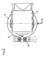
- the embodiment according to Fig. 2 in which the discharge elbow 6 is driven via a turntable 9 and a spindle drive 10, a proximity switch 11, and an optical sensor 12.
- the sensor 12 controls the turntable 9 on the provided on the turntable 9 Nullagemark réelle so that the control unit receives a control signal as soon as in the course of a pivoting movement the Nullage is reached. Thereafter, the distance traveled until the reception of the zero-crossing signal path is determined on the basis of the detected number of teeth and added by the control unit for the still after the zero position slewing angle. After reaching this added adjustment angle of the motor drive is stopped.
- the chute 6 has reached the second operating position, which corresponds to the mirrored at the vertical longitudinal center plane of the harvester 1 first operating position.
- a unit 13 which includes a gear 14 which meshes with the turntable 9.
- the number of revolutions or the partial revolution of the gear 14 is determined by the unit 15 and forwarded to the control unit.
- the rotation or partial rotation of the gear 14 until reaching the determined by the sensor 12 zero point position otherwise corresponds to the operation, as for the embodiment of Fig. 2 was explained.
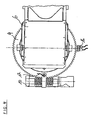
- Fig. 4 is in otherwise substantially the same design of the proximity switch 11 is replaced by a double proximity switch 16, with the addition of the direction of rotation can be detected.
- Fig. 5 illustrates once again in a perspective view of the embodiment Fig. 4
- Fig. 6 is illustrated by a block diagram, which describes the content of the individual functions, once again illustrates the operation of an embodiment of a control unit for a harvester according to the invention.
Landscapes
- Life Sciences & Earth Sciences (AREA)
- Environmental Sciences (AREA)
- Harvesting Machines For Specific Crops (AREA)
- Guiding Agricultural Machines (AREA)
- Combines (AREA)
- Harvester Elements (AREA)
- Fertilizing (AREA)
- Agricultural Machines (AREA)
- Harvesting Machines For Root Crops (AREA)
Description
- Die Erfindung bezieht sich auf eine Erntemaschine, insbesondere enen selbstfahrenden Feldhäcksler zum Aufnehmen und Häckseln von Mais, Anwelkgras, Grünfutter und dergleichen Erntegut, mit einem Einzugs- und Häckseleinrichtungen nachgeordneten, motorisch verschwenbaren Auswurfkrümmer zur Übergabe des Erntegutes in einen Laderaum eines Begleitfahrzeuges.
- Erntemaschinen der vorgenannten Art sind bekannt. Sind sie als Feldhäcksler ausgebildet, übergeben sie während der Erntefahrt das Erntegut über den Auswurfkrümmer in den Laderaum eines neben dem Feldhäcksler fahrenden Begleitfahrzeuges, das einen Abstand und eine Positionierung zum Feldhäcksler einzunehmen hat, um bei positioniertem Auswurfkrümmer möglichst ohne Verlust von Erntegut das Erntegut sicher in den Laderaum zu übergeben. Beim Wechsel der Fahrtrichtung des Feldhäckslers auf einem Vorgewende ergeben sich jedoch zeitaufwendige Neupositionierungsarbeiten zur exakten Einstellung des Auswurfkrümmers, da bei entgegengesetzter Fahrtrichtung das Begleitfahrzeug auf den schon abgeernteten Bereichen des Feldes zu fahren hat und somit der Auswurfkrümmer in die diesem abgeernteten Bereich des Feldes zugewandte Betriebsstellung zu überführen ist.
- Aus der
US-A-5,575,316 ist eine Anordnung offenbart, bei der über einen Entfernungsmesser beim Beladen eines Transportfahrzeuges durch einen Auswurfkrümmer eines Feldhäckslers die Abmessungen des Transportfahrzeuges ermittelt werden. Aus diesen Werten wird die Position des Auswurfkrümmers von einer Regeleinrichtung gesteuert. Die entsprechenden Entfernungsmesser sind dazu an geeigneten Stellen des Auswurfkrümmers angebracht und erkennen in Längs- und Querrichtung z.B. die Höhe von Begrenzungswänden des Transportfahrzeuges, so daß dann durch einen Vergleich der aktuellen Füllhöhen des eingefüllten Gutes mit der Höhe der Begrenzungswände des Ladebehälters des Transportfahrzeuges der Füllgrad ermittelt werden kann. In Abhängigkeit vom Füllgrad erfolgt eine gesteuerte Verschwenkung des Auswurfkrümmers um eine horizontale und/oder vertikale Schwenkachse oder auch eine Verschwenkung der Auswurfklappe des Auswurfkrümmers mit dem Ziel, eine Futterverluste vermeidende Beladung des Transportfahrzeuges zu erzielen. Damit ist jedoch eine exakte Neupositionierung des Auswurfkrümmers nach einem Wechsel der Fahrtrichtung auf einem Vorgewende nicht zu vollziehen. - Es ist Aufgabe der vorliegenden Erfindung, eine Erntemaschine der eingangs genannten Art zu schaffen, bei der zeitaufwendige Positionierarbeiten nach einem Fahrtrichtungswechsel zu vereinfachen sind.
- Zur Lösung dieser Aufgabe zeichnet sich die Erntemaschine der eingangs genannten Art durch die im Patentanspruch 1 angegebenen Merkmale aus. Hinsichtlich wesentlicher weiterer Ausgestaltungen wird auf die Ansprüche 2 bis 6 verwiesen.
- Damit ist es bei der Erntemaschine nach der Erfindung ermöglicht, bei Fahrtrichtungswechsel den Auswurfkrümmer automatisch in eine vorprogrammierbare, spiegelbildliche Position über die Steuervorrichtung zu überführen, so daß bei abgesprochener Positionierung des Begleitfahrzeuges und des Feldhäckslers nach einem Fahrtrichtungswechsel z.B. exakt die Positionierung des Auswurfkrümmers einzunehmen ist, die vor dem Fahrtrichtungswechsel vorgelegen hat. Dazu bedarf es keiner manuellen zeitaufwendigen Neupositionierung des Auswurfkrümmers durch die Bedienperson des Feldhäckslers. Der damit einhergehende Zeitvorteil ist während der Erntefahrt auf einem Feld erheblich. Darüber hinaus werden Positionierungsfehler wirksam verringert, so daß die Bedienperson nach Wenden der Erntemaschine sehr schnell seine Erntefahrt wiederaufnehmen kann. Die motorische Verschwenkung kann durch bekannte Antriebe wie Stellmotoren, Hydraulikeinheiten, Klinkenschaltwerke und dergleichen mechanische Antriebe erfolgen.
- Die zur Steuerung notwendigen Teile der Steuervorrichtung bauen relativ einfach. So kann auf einem Drehkranz des Auswurfkrümmers zunächst eine Markierung für eine Nullpunktlage vorgesehen sein, die von einem optischen Sensor zu erkennen ist, der ein Signal an die Steuerungseinrichtung weiterleitet. Über einen Näherungsschalter, aber auch zum Beispiel über ein mit dem Drehkranz des Auswurfkrümmer kämmendes Zahnrad, ist das Winkelmaß von der ersten Betriebsstellung heraus bishin zur Nullpunktlage mit einfachen baulichen Teilen zu ermitteln, so daß zur Einnahme der gespiegelten ersten Betriebsstellung (2. Betriebsstellung) dann von der Steuereinheit nur noch das Winkelmaß, das durchfahren wurde bis zum Erreichen der Nullpunktstellung, zu addieren ist, um den Auswurfkrümmer in der zweiten Betriebsstellung zu positionieren. Die Winkelmessung muß allerdings nicht zwingend digital erfolgen. Darüber hinaus können auch analoge Sensoren Einsatz finden. Auch inkremental kann die Winkelmessung erfolgen. Weitere Automatikfunktionen können über die Teile zur Winkelmessung realisiert werden.
- Weitere Einzelheiten und Vorteile der Erfindung ergeben sich aus weiteren Unteransprüchen, der nachfolgenden Beschreibung und der Zeichnung.
- In der Zeichnung zeigen:
- Fig. 1
- eine schematische Draufsicht auf einen Feldhäcksler mit Begleitfahrzeug während der Erntearbeit,
- Fig. 2
- ausschnittsweise in schematischer Draufsicht den sich an einen Drehkranzantrieb anschließenden Bereich eines Auswurfkrümmers,
- Fig. 3
- ausschnittsweise ein alternatives Ausführungsbeispiel zu dem Ausführungsbeispiel nach
Fig. 2 in einer schematischen perspektivischen Darstellung schräg von oben auf den Antriebsbereich des Auswurfkrümmers; - Fig. 4
- eine zu
Fig. 2 analoge Darstellung eines alternativen Ausführungsbeispiels, - Fig. 5
- eine zu
Fig. 3 analoge Darstellung eines alternativen Ausführungsbeispiels und - Fig. 6
- ein beschriftetes Blockschaltbild für die Steuerung eines Ausführungsbeispiels einer Steuereinheit für eine Erntemaschine nach der Erfindung.
- Die in der Zeichnung allgemein mit 1 bezifferte Erntemaschine ist als selbstfahrender Feldhäcksler ausgebildet und hat als Vorsatzgerät ein Maisgebiß 2, ein Fahrgestell 3, von einem Gehäuse 4 abgedeckte feldhäckslertypische Einheiten wie Motor- und Getriebeeinheiten, Einzugsorgane und Häckseleinrichtungen, eine Fahrerkabine 5 sowie einen motorisch verschwenkbaren Auswurfkrümmer 6. In der
Fig. 1 dargestellt ist noch ein landwirtschaftlicher Schlepper 7, der einen Hänger 8 zieht, in dessen Laderaum 9 der Auswurfkrümmer das Erntegut zu übergeben hat. Um auch bei Wechsel der Fahrtrichtung des Feldhäckslers 1 und des Gespanns aus landwirtschaftlichem Schlepper 7 und Hänger 8 den Auswurfkrümmer 6 wieder exakt positionieren zu können, ist der motorische Schwenkantrieb des Auswurfkrümmers 6 mit einer Steuereinheit verbunden, die den Auswurfkrümmer 6 aus der inFig. 1 mit Volllinien markierten ersten Betriebsstellung, in die der vertikalen Längsmittelebene des Feldhäckslers 1 gespiegelte ersten Betriebsstellung überführt, die der zweiten Betriebsstellung entspricht, wie sie gestrichelt inFig. 1 dargestellt ist. - Damit lassen sich die Positionierarbeiten nach einem Fahrtrichtungswechsel sowohl des Feldhäckslers 1 als auch des landwirtschaftlichen Schleppers 7 sehr vereinfachen, indem der Schlepperfahrer nur noch die abgesprochene Position zum Feldhäcksler hin einnehmen muß, der Auswurfkrümmer 6 jedoch automatisch über den motorischen Antrieb und die mit ihm gekoppelte Steuereinrichtung die bei der letzten Erntefahrt vorgesehene Winkelauswurfstellung einnimmt.
- Dazu weist das Ausführungsbeispiel nach
Fig. 2 , bei dem der Auswurfkrümmer 6 über einen Drehkranz 9 und einen Spindelantrieb 10 angetrieben ist, einen Näherungsschalter 11, sowie einen optischen Sensor 12 auf. Der Näherungsschalter 11 ermittelt die im Verlaufe einer Schwenkbewegung des Drehkranzes 9 an ihm vorbeifahrenden Zähne des Drehkranzes 9. Der Sensor 12 kontrolliert den Drehkranz 9 auf die auf dem Drehkranz 9 vorgesehene Nullagemarkierung, so daß die Steuereinheit ein Steuersignal erhält, sobald im Verlaufe einer Verschwenkbewegung die Nullage erreicht ist. Danach wird die bis zum Empfang des Nullagensignals zurückgelegte Wegstrecke aufgrund der erfaßten Zähnezahl bestimmt und von der Steuereinheit für den nach der Nullage noch zurücklegenden Schwenkwinkel hinzuaddiert. Nach Erreichen dieses hinzuaddierten Verstellwinkels wird der motorische Antrieb gestoppt. Der Auswurfkrümmer 6 hat die zweite Betriebsstellung erreicht, die der an der vertikalen Längsmittelebene der Erntemaschine 1 gespiegelten ersten Betriebsstellung entspricht. - In dem Ausführungsbeispiel nach
Fig. 3 ist anstelle des Näherungsschalters 11 eine Einheit 13 vorgesehen, die ein Zahnrad 14 umfaßt, das mit dem Drehkranz 9 kämmt. Die Umdrehungszahl beziehungsweise die Teilumdrehung des Zahnrades 14 wird über die Einheit 15 ermittelt und an die Steuereinheit weitergeleitet. Die Umdrehung beziehungsweise Teilumdrehung des Zahnrades 14 bis zum Erreichen der durch den Sensor 12 ermittelten Nullpunktlage entspricht ansonsten der Arbeitsweise, wie sie für das Ausführungsbeispiel nachFig. 2 erläutert wurde. InFig. 4 ist bei ansonsten im wesentlichen gleicher Gestaltung der Näherungsschalter 11 durch einen Doppelnäherungsschalter 16 ersetzt, mit dem zusätzlich die Drehrichtung erfaßt werden kann. -
Fig. 5 verdeutlicht noch einmal in einer perspektivischen Ansicht das Ausführungsbeispiel nachFig. 4 . InFig. 6 ist anhand eines Blockschaltbildes, das die einzelnen Funktionen inhaltlich beschreibt, noch einmal die Wirkungsweise eines Ausführungsbeispiels einer Steuereinheit für eine Erntemaschine nach der Erfindung veranschaulicht.
Claims (6)
- Erntemaschine (1), insbesondere selbstfahrender Feldhäcksler zum Aufnehmen und Häckseln von Mais, Anwelkgras, Grünfutter und dergleichen Erntegut, mit einem Einzugs- und Häckseleinrichtungen nachgeordneten, von einem motorischen Antrieb verschwenkbaren Auswurfkrümer (6) zur Übergabe des Erntegutes in einen Laderaum eines Begleitfahrzeugs, dadurch gekennzeichnet, daß der Auswurfkrümmer (6) über den motorischen Antrieb und eine mit diesem gekoppelte Steuervorrichtung bei einem Fahrtrichtungswechsel aus der letzten Betriebsstellung des Auswurfkrümmers (6) vor dem Fahrtrichtungswechsel nach Betätigung einer Starttaste "Bogenspiegeln" der Steuervorrichtung automatisch in eine vorprogrammierbare Betriebsstellung nach dem Fahrtrichtungswechsel verschwenkbar ist, die der an der vertikalen Längsmittelebene der Erntemaschine (1) gespiegelten Betriebsstellung vor dem Fahrtrichtungswechsel entspricht.
- Erntemaschine nach Anspruch 1, dadurch gekennzeichnet, daß die Steuervorrichtung einen Nullage-Sensor (12), einen Winkelmeßzähler (11, 13, 14, 15, 16) sowie eine Soll-/Istwert-Vergleich-Kontrolleinheit umfaßt.
- Erntemaschine nach Anspruch 1 oder 2 mit einem über einen Drehkranz (9) verschwenkbaren Auswurfkrümmer (6), dadurch gekennzeichnet, daß der Winkelmeßzähler (11, 16) als die Zähne des Drehkranzes (9) zählender Näherungsschalter ausgebildet ist.
- Erntemaschine nach Anspruch 3, dadurch gekennzeichnet, daß auf dem Drehkranz (9) des Auswurfkrümmers (6) eine Nullagemarkierung angebracht ist, die über einen Näherungssensor (12) gelesen wird.
- Erntemaschine nach einem der Ansprüche 2 bis 4, dadurch gekennzeichnet, daß der Winkelmeßzähler als ein mit dem Antrieb des Auswurfkrümmers (6) bewegbares Zählwerk (13) ausgebildet ist.
- Erntemaschine nach Anspruch 5, dadurch gekennzeichnet, daß das Zählwerk (13) ein mit dem Drehkranz (9) des Auswurfkrümmers (6) kämmendes Zahnrad (14) aufweist.
Applications Claiming Priority (2)
| Application Number | Priority Date | Filing Date | Title |
|---|---|---|---|
| DE10021664 | 2000-05-04 | ||
| DE10021664A DE10021664B4 (de) | 2000-05-04 | 2000-05-04 | Erntemaschine, insbesondere selbstfahrender Feldhäcksler |
Publications (3)
| Publication Number | Publication Date |
|---|---|
| EP1151652A1 EP1151652A1 (de) | 2001-11-07 |
| EP1151652B1 EP1151652B1 (de) | 2007-06-13 |
| EP1151652B2 true EP1151652B2 (de) | 2012-06-20 |
Family
ID=7640726
Family Applications (1)
| Application Number | Title | Priority Date | Filing Date |
|---|---|---|---|
| EP01108273A Expired - Lifetime EP1151652B2 (de) | 2000-05-04 | 2001-04-02 | Erntemaschine, insbesondere selbstfahrender Feldhäcksler |
Country Status (4)
| Country | Link |
|---|---|
| US (1) | US6638159B2 (de) |
| EP (1) | EP1151652B2 (de) |
| AT (1) | ATE364310T1 (de) |
| DE (2) | DE10021664B4 (de) |
Families Citing this family (29)
| Publication number | Priority date | Publication date | Assignee | Title |
|---|---|---|---|---|
| DE10119279A1 (de) * | 2001-04-20 | 2002-10-24 | Deere & Co | Einrichtung zur Steuerung der Position einer Austrageinrichtung einer landwirtschaftlichen Erntemaschine |
| DE10134137B4 (de) * | 2001-07-13 | 2006-02-23 | Maschinenfabrik Bernard Krone Gmbh | Selbstfahrende landwirtschaftliche Erntemaschine |
| DE10207479A1 (de) | 2002-02-22 | 2003-10-16 | Deere & Co | Verteilvorrichtung für aus einer Erntemaschine austretendes Häckselgut |
| DE10240219A1 (de) * | 2002-08-28 | 2004-03-11 | Claas Selbstfahrende Erntemaschinen Gmbh | Vorrichtung zur Steuerung einer Überladeeinrichtung |
| DE10242164A1 (de) * | 2002-09-10 | 2004-04-01 | Claas Selbstfahrende Erntemaschinen Gmbh | Verfahren zur Steuerung einer Überladeeinrichtung |
| DE10309700B4 (de) | 2003-03-06 | 2012-07-12 | Deere & Company | Austrageinrichtung einer landwirtschaftlichen Erntemaschine |
| DE10317816A1 (de) * | 2003-04-16 | 2004-11-04 | Claas Selbstfahrende Erntemaschinen Gmbh | Feldhäcksler mit positionierbarer Fahrerkabine |
| DE102004020127A1 (de) * | 2004-04-24 | 2005-11-24 | Deere & Company, Moline | Erntemaschine mit einer Austrageinrichtung |
| DE102004035158A1 (de) * | 2004-07-20 | 2006-02-16 | Deere & Company, Moline | Austrageinrichtung einer landwirtschaftlichen Erntemaschine |
| DE102008014001A1 (de) † | 2008-03-13 | 2009-09-17 | Claas Selbstfahrende Erntemaschinen Gmbh | Landwirtschaftliche Erntemaschine mit einer Überladeeinrichtung |
| US8398469B2 (en) * | 2008-07-09 | 2013-03-19 | Deere & Company | Agricultural work machine having an unloading system for unloading an agricultural product |
| US7806757B2 (en) * | 2008-07-16 | 2010-10-05 | Deere & Company | Dual sided belted unloader |
| US20100016046A1 (en) * | 2008-07-16 | 2010-01-21 | Coers Bruce A | Flexible unloading tube |
| US7938613B2 (en) * | 2009-04-15 | 2011-05-10 | Cnh America Llc | Grain unloading conveyor with directable spout and closure apparatus and system |
| DE102009042371A1 (de) * | 2009-09-23 | 2011-03-24 | Claas Selbstfahrende Erntemaschinen Gmbh | Vorrichtung zur Positionserfassung einer gegenüber einem Maschinengehäuse einer Erntemaschine um eine Schwenkachse schwenkbaren Überladeeinrichtung |
| US8186497B2 (en) | 2009-10-13 | 2012-05-29 | Deere & Company | Unloading conveyor suspension system |
| US8010262B2 (en) * | 2009-10-21 | 2011-08-30 | Cnh America Llc | Apparatus and method for automatically controlling the settings of an adjustable crop residue spreader of an agricultural combine |
| US8197312B2 (en) * | 2009-12-04 | 2012-06-12 | Cnh America Llc | Extension for an agricultural combine unloader tube |
| US20110164952A1 (en) * | 2010-01-06 | 2011-07-07 | Hollenberg David H | Grain cart with directional discharge |
| CA2810188A1 (en) | 2010-03-11 | 2011-09-15 | Partners In Innovation Limited, Llc | Multi-functional and modular tree removal and maintenance apparatus and related methods |
| US8739843B2 (en) | 2010-03-11 | 2014-06-03 | Partners In Innovation Limited, Llc | Multi-functional and modular tree removal and maintenance apparatus and related methods |
| DE102011050629A1 (de) * | 2011-05-25 | 2012-11-29 | Claas Selbstfahrende Erntemaschinen Gmbh | Erntevorrichtung |
| US20130019580A1 (en) * | 2011-07-20 | 2013-01-24 | Anderson Noel W | Bidirectional harvesting system |
| US10299433B2 (en) | 2014-11-19 | 2019-05-28 | Agco Corporation | Unloading conveyor swing control system |
| DE102015103923A1 (de) * | 2015-03-17 | 2016-09-22 | Claas Selbstfahrende Erntemaschinen Gmbh | Feldhäcksler |
| US9675008B1 (en) | 2016-02-29 | 2017-06-13 | Cnh Industrial America Llc | Unloading arrangement for agricultural harvesting vehicles |
| DE102019203539A1 (de) | 2019-03-15 | 2020-09-17 | Deere & Company | System zur Kontrolle eines mit einem Fahrzeug verbundenen Arbeitsgeräts |
| US10750668B1 (en) | 2019-07-10 | 2020-08-25 | Cnh Industrial America Llc | Self-cleaning unloader assembly |
| US12234099B2 (en) | 2021-12-16 | 2025-02-25 | Cnh Industrial America Llc | Crop unloader drive with tensioner |
Citations (1)
| Publication number | Priority date | Publication date | Assignee | Title |
|---|---|---|---|---|
| DE4403893A1 (de) † | 1994-02-08 | 1995-08-10 | Claas Ohg | Vorrichtung zur automatischen Befüllung von Ladebehältern mit einem Gutstrom |
Family Cites Families (12)
| Publication number | Priority date | Publication date | Assignee | Title |
|---|---|---|---|---|
| US3786945A (en) * | 1973-01-15 | 1974-01-22 | Deere & Co | Spout control system |
| US4042132A (en) * | 1976-06-01 | 1977-08-16 | Sperry Rand Corporation | Spout control apparatus for agricultural machines |
| DE3011822A1 (de) * | 1980-03-27 | 1981-10-01 | Robert Bosch Gmbh, 7000 Stuttgart | Sensoranordnung |
| US4376609A (en) * | 1980-03-31 | 1983-03-15 | Sperry Corporation | Automatic spout control for agricultural machines |
| US4529348A (en) * | 1983-04-06 | 1985-07-16 | Deere & Company | Spout aimer |
| US5359838A (en) * | 1994-01-27 | 1994-11-01 | Madsen William H | Apparatus for controlling the direction of a crop discharge spout on agricultural machinery with respect to an associated collector |
| GB2287633A (en) * | 1994-03-16 | 1995-09-27 | New Holland Belguim Nv | Forage harvester |
| DE4427220C2 (de) * | 1994-08-01 | 1997-12-04 | Siemens Ag | Magnetischer Näherungsdetektor |
| DE19531662A1 (de) * | 1995-08-29 | 1997-03-06 | Claas Ohg | Vorrichtung zum automatischen Befüllen von Ladebehältern |
| JPH1015A (ja) | 1996-06-13 | 1998-01-06 | Kubota Corp | コンバイン |
| DE19647522A1 (de) * | 1996-11-16 | 1998-05-20 | Claas Ohg | Vorrichtung zur Überwachung der Überladung von Gütern von einer Arbeitsmaschine auf ein Transportfahrzeug |
| DE19848127A1 (de) * | 1998-10-19 | 2000-04-20 | Claas Selbstfahr Erntemasch | Vorrichtung zur Steuerung einer Überladeeinrichtung |
-
2000
- 2000-05-04 DE DE10021664A patent/DE10021664B4/de not_active Expired - Fee Related
-
2001
- 2001-04-02 DE DE50112617T patent/DE50112617D1/de not_active Expired - Lifetime
- 2001-04-02 AT AT01108273T patent/ATE364310T1/de not_active IP Right Cessation
- 2001-04-02 EP EP01108273A patent/EP1151652B2/de not_active Expired - Lifetime
- 2001-05-02 US US09/847,541 patent/US6638159B2/en not_active Expired - Lifetime
Patent Citations (1)
| Publication number | Priority date | Publication date | Assignee | Title |
|---|---|---|---|---|
| DE4403893A1 (de) † | 1994-02-08 | 1995-08-10 | Claas Ohg | Vorrichtung zur automatischen Befüllung von Ladebehältern mit einem Gutstrom |
Also Published As
| Publication number | Publication date |
|---|---|
| DE50112617D1 (de) | 2007-07-26 |
| EP1151652A1 (de) | 2001-11-07 |
| ATE364310T1 (de) | 2007-07-15 |
| EP1151652B1 (de) | 2007-06-13 |
| US6638159B2 (en) | 2003-10-28 |
| DE10021664B4 (de) | 2004-05-06 |
| US20020095923A1 (en) | 2002-07-25 |
| DE10021664A1 (de) | 2001-11-15 |
Similar Documents
| Publication | Publication Date | Title |
|---|---|---|
| EP1151652B1 (de) | Erntemaschine, insbesondere selbstfahrender Feldhäcksler | |
| BE1020387A5 (de) | Anordnung und verfahren zur selbsttätigen überladung von erntegut von einer erntemaschine auf ein transportfahrzeug. | |
| EP1219159A1 (de) | Vorrichtung und Verfahren zur automatischen Steuerung einer Überladeeinrichtung an landwirtschaftlichen Erntemaschinen | |
| EP0995351A1 (de) | Vorrichtung zur Steuerung einer Überladeeinrichtung | |
| DE102008002006A1 (de) | Steueranordnung zur Kontrolle des Überladens landwirtschaftlichen Ernteguts von einer Erntemaschine auf ein Transportfahrzeug | |
| EP3646701B1 (de) | Mähdrescher mit einer anordnung zur steuerung des betriebs eines bandschneidwerks | |
| EP1362504A1 (de) | Maschine zum Mähen von stängelartigem Erntegut | |
| EP3915353B1 (de) | Verfahren zur bestimmung der position einer an einer überladevorrichtung einer selbstfahrenden erntemaschine angeordneten kamera | |
| EP2564683B1 (de) | System zur Steuerung einer Überladeeinrichtung | |
| EP1093708A1 (de) | Mähgerät | |
| DE102008001779B4 (de) | Erntevorsatz mit einem Gutaufnehmer und einer Querförderschnecke | |
| DE102012004045A1 (de) | "Erntemaschine mit wenigstens einem Querförderer" | |
| EP1796454B1 (de) | Erntegerät, insbesondere erntevorsatz für landwirtschaftliche erntemaschinen zum aufnehmen und weiterfördern von halmfrüchten | |
| EP1736043B1 (de) | Steuerung für Kreiselschwader und Mähwerke als landwirtschaftliche Arbeitsmaschinen | |
| EP1523872B1 (de) | Landwirtschaftliche Arbeitsmaschine | |
| EP3791707A1 (de) | Vorrichtung zum bodennahen bearbeiten von pflanzlichem material und verfahren zum bodennahen bearbeiten von pflanzlichem material | |
| DE102019005662A1 (de) | Auswurfkrümmer für einen Feldhäcksler | |
| EP1588601B1 (de) | Erntemaschine mit einer Austrageinrichtung | |
| DE19934882B4 (de) | Meßeinrichtung | |
| DE102008040217B4 (de) | Zwischen einer Betriebsstellung und einer kompakten Transportstellung verstellbarer Erntevorsatz | |
| DE20108319U1 (de) | Arbeitsaggregatekombination | |
| EP3791706B1 (de) | Landwirtschaftliche arbeitsmaschine mit höhenveränderbarem arbeitswerkzeug | |
| BE1029116B1 (de) | Steuersystem zur Steuerung eines beweglichen Elements einer Erntemaschine | |
| EP2865259B1 (de) | Verbesserter Antriebsstrang für einen Großschwader | |
| EP4129036A1 (de) | Landwirtschaftliche maschine mit kameraüberwachter komponente |
Legal Events
| Date | Code | Title | Description |
|---|---|---|---|
| PUAI | Public reference made under article 153(3) epc to a published international application that has entered the european phase |
Free format text: ORIGINAL CODE: 0009012 |
|
| AK | Designated contracting states |
Kind code of ref document: A1 Designated state(s): AT BE CH CY DE DK ES FI FR GB GR IE IT LI LU MC NL PT SE TR |
|
| AX | Request for extension of the european patent |
Free format text: AL;LT;LV;MK;RO;SI |
|
| 17P | Request for examination filed |
Effective date: 20020405 |
|
| AKX | Designation fees paid |
Free format text: AT BE CH CY DE DK ES FI FR GB GR IE IT LI LU MC NL PT SE TR |
|
| 17Q | First examination report despatched |
Effective date: 20050310 |
|
| 17Q | First examination report despatched |
Effective date: 20050310 |
|
| GRAP | Despatch of communication of intention to grant a patent |
Free format text: ORIGINAL CODE: EPIDOSNIGR1 |
|
| GRAS | Grant fee paid |
Free format text: ORIGINAL CODE: EPIDOSNIGR3 |
|
| GRAA | (expected) grant |
Free format text: ORIGINAL CODE: 0009210 |
|
| AK | Designated contracting states |
Kind code of ref document: B1 Designated state(s): AT BE CH CY DE DK ES FI FR GB GR IE IT LI LU MC NL PT SE TR |
|
| REG | Reference to a national code |
Ref country code: GB Ref legal event code: FG4D Free format text: NOT ENGLISH |
|
| REG | Reference to a national code |
Ref country code: CH Ref legal event code: EP |
|
| REG | Reference to a national code |
Ref country code: IE Ref legal event code: FG4D Free format text: LANGUAGE OF EP DOCUMENT: GERMAN |
|
| REF | Corresponds to: |
Ref document number: 50112617 Country of ref document: DE Date of ref document: 20070726 Kind code of ref document: P |
|
| PG25 | Lapsed in a contracting state [announced via postgrant information from national office to epo] |
Ref country code: SE Free format text: LAPSE BECAUSE OF FAILURE TO SUBMIT A TRANSLATION OF THE DESCRIPTION OR TO PAY THE FEE WITHIN THE PRESCRIBED TIME-LIMIT Effective date: 20070913 |
|
| ET | Fr: translation filed | ||
| NLV1 | Nl: lapsed or annulled due to failure to fulfill the requirements of art. 29p and 29m of the patents act | ||
| GBV | Gb: ep patent (uk) treated as always having been void in accordance with gb section 77(7)/1977 [no translation filed] |
Effective date: 20070613 |
|
| REG | Reference to a national code |
Ref country code: IE Ref legal event code: FD4D |
|
| PG25 | Lapsed in a contracting state [announced via postgrant information from national office to epo] |
Ref country code: ES Free format text: LAPSE BECAUSE OF FAILURE TO SUBMIT A TRANSLATION OF THE DESCRIPTION OR TO PAY THE FEE WITHIN THE PRESCRIBED TIME-LIMIT Effective date: 20070924 Ref country code: NL Free format text: LAPSE BECAUSE OF FAILURE TO SUBMIT A TRANSLATION OF THE DESCRIPTION OR TO PAY THE FEE WITHIN THE PRESCRIBED TIME-LIMIT Effective date: 20070613 Ref country code: IE Free format text: LAPSE BECAUSE OF FAILURE TO SUBMIT A TRANSLATION OF THE DESCRIPTION OR TO PAY THE FEE WITHIN THE PRESCRIBED TIME-LIMIT Effective date: 20070613 Ref country code: PT Free format text: LAPSE BECAUSE OF FAILURE TO SUBMIT A TRANSLATION OF THE DESCRIPTION OR TO PAY THE FEE WITHIN THE PRESCRIBED TIME-LIMIT Effective date: 20071113 |
|
| PLBI | Opposition filed |
Free format text: ORIGINAL CODE: 0009260 |
|
| PLAX | Notice of opposition and request to file observation + time limit sent |
Free format text: ORIGINAL CODE: EPIDOSNOBS2 |
|
| 26 | Opposition filed |
Opponent name: CNH BELGIUM N.V. Effective date: 20080313 |
|
| PG25 | Lapsed in a contracting state [announced via postgrant information from national office to epo] |
Ref country code: DK Free format text: LAPSE BECAUSE OF FAILURE TO SUBMIT A TRANSLATION OF THE DESCRIPTION OR TO PAY THE FEE WITHIN THE PRESCRIBED TIME-LIMIT Effective date: 20070613 Ref country code: GB Free format text: LAPSE BECAUSE OF FAILURE TO SUBMIT A TRANSLATION OF THE DESCRIPTION OR TO PAY THE FEE WITHIN THE PRESCRIBED TIME-LIMIT Effective date: 20070613 Ref country code: GR Free format text: LAPSE BECAUSE OF FAILURE TO SUBMIT A TRANSLATION OF THE DESCRIPTION OR TO PAY THE FEE WITHIN THE PRESCRIBED TIME-LIMIT Effective date: 20070914 |
|
| PLAF | Information modified related to communication of a notice of opposition and request to file observations + time limit |
Free format text: ORIGINAL CODE: EPIDOSCOBS2 |
|
| PLBB | Reply of patent proprietor to notice(s) of opposition received |
Free format text: ORIGINAL CODE: EPIDOSNOBS3 |
|
| PG25 | Lapsed in a contracting state [announced via postgrant information from national office to epo] |
Ref country code: MC Free format text: LAPSE BECAUSE OF NON-PAYMENT OF DUE FEES Effective date: 20080430 |
|
| REG | Reference to a national code |
Ref country code: CH Ref legal event code: PL |
|
| PG25 | Lapsed in a contracting state [announced via postgrant information from national office to epo] |
Ref country code: CH Free format text: LAPSE BECAUSE OF NON-PAYMENT OF DUE FEES Effective date: 20080430 Ref country code: LI Free format text: LAPSE BECAUSE OF NON-PAYMENT OF DUE FEES Effective date: 20080430 |
|
| PG25 | Lapsed in a contracting state [announced via postgrant information from national office to epo] |
Ref country code: FI Free format text: LAPSE BECAUSE OF FAILURE TO SUBMIT A TRANSLATION OF THE DESCRIPTION OR TO PAY THE FEE WITHIN THE PRESCRIBED TIME-LIMIT Effective date: 20070613 |
|
| PG25 | Lapsed in a contracting state [announced via postgrant information from national office to epo] |
Ref country code: CY Free format text: LAPSE BECAUSE OF FAILURE TO SUBMIT A TRANSLATION OF THE DESCRIPTION OR TO PAY THE FEE WITHIN THE PRESCRIBED TIME-LIMIT Effective date: 20070613 |
|
| PGFP | Annual fee paid to national office [announced via postgrant information from national office to epo] |
Ref country code: AT Payment date: 20090424 Year of fee payment: 9 |
|
| PG25 | Lapsed in a contracting state [announced via postgrant information from national office to epo] |
Ref country code: LU Free format text: LAPSE BECAUSE OF NON-PAYMENT OF DUE FEES Effective date: 20080402 |
|
| PGFP | Annual fee paid to national office [announced via postgrant information from national office to epo] |
Ref country code: FR Payment date: 20100519 Year of fee payment: 10 |
|
| PG25 | Lapsed in a contracting state [announced via postgrant information from national office to epo] |
Ref country code: TR Free format text: LAPSE BECAUSE OF FAILURE TO SUBMIT A TRANSLATION OF THE DESCRIPTION OR TO PAY THE FEE WITHIN THE PRESCRIBED TIME-LIMIT Effective date: 20070613 |
|
| PG25 | Lapsed in a contracting state [announced via postgrant information from national office to epo] |
Ref country code: AT Free format text: LAPSE BECAUSE OF NON-PAYMENT OF DUE FEES Effective date: 20100402 |
|
| REG | Reference to a national code |
Ref country code: FR Ref legal event code: ST Effective date: 20111230 |
|
| PG25 | Lapsed in a contracting state [announced via postgrant information from national office to epo] |
Ref country code: FR Free format text: LAPSE BECAUSE OF NON-PAYMENT OF DUE FEES Effective date: 20110502 |
|
| PUAH | Patent maintained in amended form |
Free format text: ORIGINAL CODE: 0009272 |
|
| STAA | Information on the status of an ep patent application or granted ep patent |
Free format text: STATUS: PATENT MAINTAINED AS AMENDED |
|
| 27A | Patent maintained in amended form |
Effective date: 20120620 |
|
| AK | Designated contracting states |
Kind code of ref document: B2 Designated state(s): AT BE CH CY DE DK ES FI FR GB GR IE IT LI LU MC NL PT SE TR |
|
| REG | Reference to a national code |
Ref country code: DE Ref legal event code: R102 Ref document number: 50112617 Country of ref document: DE Effective date: 20120620 |
|
| PGFP | Annual fee paid to national office [announced via postgrant information from national office to epo] |
Ref country code: IT Payment date: 20150422 Year of fee payment: 15 |
|
| PG25 | Lapsed in a contracting state [announced via postgrant information from national office to epo] |
Ref country code: IT Free format text: LAPSE BECAUSE OF NON-PAYMENT OF DUE FEES Effective date: 20160402 |
|
| REG | Reference to a national code |
Ref country code: DE Ref legal event code: R084 Ref document number: 50112617 Country of ref document: DE |
|
| PGFP | Annual fee paid to national office [announced via postgrant information from national office to epo] |
Ref country code: DE Payment date: 20190418 Year of fee payment: 19 |
|
| PGFP | Annual fee paid to national office [announced via postgrant information from national office to epo] |
Ref country code: BE Payment date: 20200428 Year of fee payment: 20 |
|
| REG | Reference to a national code |
Ref country code: DE Ref legal event code: R119 Ref document number: 50112617 Country of ref document: DE |
|
| PG25 | Lapsed in a contracting state [announced via postgrant information from national office to epo] |
Ref country code: DE Free format text: LAPSE BECAUSE OF NON-PAYMENT OF DUE FEES Effective date: 20201103 |
|
| REG | Reference to a national code |
Ref country code: BE Ref legal event code: MK Effective date: 20210402 |