EP1150863B1 - Bicycle carrier - Google Patents
Bicycle carrier Download PDFInfo
- Publication number
- EP1150863B1 EP1150863B1 EP99961256A EP99961256A EP1150863B1 EP 1150863 B1 EP1150863 B1 EP 1150863B1 EP 99961256 A EP99961256 A EP 99961256A EP 99961256 A EP99961256 A EP 99961256A EP 1150863 B1 EP1150863 B1 EP 1150863B1
- Authority
- EP
- European Patent Office
- Prior art keywords
- gripping unit
- bicycle
- carrier system
- gripping
- bicycle carrier
- Prior art date
- Legal status (The legal status is an assumption and is not a legal conclusion. Google has not performed a legal analysis and makes no representation as to the accuracy of the status listed.)
- Expired - Lifetime
Links
- 238000010168 coupling process Methods 0.000 claims abstract description 74
- 238000005859 coupling reaction Methods 0.000 claims abstract description 74
- 230000008878 coupling Effects 0.000 claims abstract description 71
- 230000000295 complement effect Effects 0.000 claims description 12
- 230000035939 shock Effects 0.000 claims description 6
- 238000003780 insertion Methods 0.000 claims description 3
- 230000037431 insertion Effects 0.000 claims description 3
- 239000000969 carrier Substances 0.000 description 13
- 239000000463 material Substances 0.000 description 7
- 239000010985 leather Substances 0.000 description 3
- 239000004033 plastic Substances 0.000 description 3
- 238000002835 absorbance Methods 0.000 description 2
- 239000000446 fuel Substances 0.000 description 2
- 239000002184 metal Substances 0.000 description 2
- 238000003466 welding Methods 0.000 description 2
- OKTJSMMVPCPJKN-UHFFFAOYSA-N Carbon Chemical compound [C] OKTJSMMVPCPJKN-UHFFFAOYSA-N 0.000 description 1
- 238000010521 absorption reaction Methods 0.000 description 1
- 230000006978 adaptation Effects 0.000 description 1
- 229910052799 carbon Inorganic materials 0.000 description 1
- 239000002131 composite material Substances 0.000 description 1
- 239000012050 conventional carrier Substances 0.000 description 1
- 238000006073 displacement reaction Methods 0.000 description 1
- 239000000835 fiber Substances 0.000 description 1
- 238000009434 installation Methods 0.000 description 1
- 238000012856 packing Methods 0.000 description 1
- 239000003973 paint Substances 0.000 description 1
- 238000000926 separation method Methods 0.000 description 1
- 230000003068 static effect Effects 0.000 description 1
- 238000005728 strengthening Methods 0.000 description 1
Images








Classifications
-
- B—PERFORMING OPERATIONS; TRANSPORTING
- B60—VEHICLES IN GENERAL
- B60R—VEHICLES, VEHICLE FITTINGS, OR VEHICLE PARTS, NOT OTHERWISE PROVIDED FOR
- B60R9/00—Supplementary fittings on vehicle exterior for carrying loads, e.g. luggage, sports gear or the like
- B60R9/08—Supplementary fittings on vehicle exterior for carrying loads, e.g. luggage, sports gear or the like specially adapted for sports gear
- B60R9/10—Supplementary fittings on vehicle exterior for carrying loads, e.g. luggage, sports gear or the like specially adapted for sports gear for cycles
Definitions
- the present invention relates to a bicycle carrier capable of being mounted on the top of a vehicle.
- the present invention relates to a carrier on top of a vehicle for carrying one or more bicycles, individually or in clamped pairs or clusters, each in a vertically inverted configuration.
- bicycle carriers for vehicles are known. Some of these carriers are attached to the frame of the roof rack of the vehicle. For example, bicycle carriers for a top of a vehicle are disclosed, in US 3,848,784, US 4,088,253, and in US 5,360,151.
- US 4,219,142 discloses a bicycle carrier for carrying a bicycle in an upside down configuration on a roof of a vehicle, which comprises suction cups. This carrier requires the removal of the bicycle seat.
- Some conventional bicycle carriers hold the bicycle in a prone configuration. This configuration suffers from the drawback that the bicycle occupies a large space, and therefore no more than one or two bicycles can be simultaneously carried.
- Other conventional carriers hold the bicycle in a standing configuration. In this case, the bicycle stands on its wheels and is coupled to the carrier. In the standing configuration, the bicycle occupies less space and therefore, more bicycles, up to four; can be carried side by side, possibly in a staggered arrangement.
- US 3,848,784 discloses a bicycle carrier which holds the bicycle in a standing configuration, and which requires the disassembling of the front wheel of the bicycle.
- the carrying of bicycles by the conventional standing configuration type carriers suffers from one or more of the following drawbacks.
- the drag contribution of the bicycle due to the air flow, particularly when the vehicle moves fast, is significant.
- the carriers of the standing configuration type couple each bicycle in two locations to the roof rack, one at the bicycle's front wheel, and a second at the bicycle back wheel. Therefore, these carriers are relatively complicated in structure.
- These prior art type carriers generally comprise strong elongated levers for supporting the bicycle at its upper portion, in order to overcome the forces on the bicycle.
- the mounting of the bicycle on the rooftop by this type of carrier is complicated, requires significant effort, and is time consuming to mount.
- the existing bicycle carriers cause a significant drag even when they are not in use, and when bicycles are not connected to them, as they generally comprise some high, and/or large surface parts. The significant drag generally results in an increase in fuel consumption, with accompanying high levels of noise.
- US 3,931,919 represents an improvement on the above systems in that a bicycle carrier is provided for carrying a single bicycle in upside-down configuration on the roof of a vehicle, without the need to dismantle any part of the bicycle.
- the carrier disclosed by this patent has a number of drawbacks. For example, three clamps are used for securing a bicycle onto two parallel bars on the roof of a vehicle, and each of the clamps requires some time and expertise to operate.
- no details are disclosed on how more than one bicycle is actually secured on the vehicle.
- the clamps are each adapted for securing a single bicycle only onto the roof, and therefore in order to secure more bicycles, further sets of three clamps each would be required, spaced on the parallel bars from the clamps of the first bicycle, thereby severely limiting the number of bicycles that may be secured on a given vehicle roof.
- a carrier for carrying on the trunk of a vehicle a number of bicycles in upside configuration and staggered longitudinal relationship.
- two seating members are used for seating the handlebars thereof, and straps are used around the steering column and around the rear wheel to secure the bicycle onto the carrier. Staggering between adjacent bicycles is made possible by offsetting the longitudinal position of each adjacent pair of cups.
- the carrier is thus awkward to use, relying on a multitude of straps for securing each bicycle, which gets more difficult as more bicycles are added onto the carrier.
- the pairs of cups are adapted for seating only a single bicycle onto the trunk, and therefor in order to seat more bicycles, further sets of cups are required.
- the system is in not versatile, and is in any case not meant for use on the roof of a vehicle, but rather restricted to the trunk thereof only.
- DE-A-2 635 825 showing the features of the preamble of claim 1 relates to a cumbersome assembly comprising a clamping system wherein a plurality of individual gripping units, each for gripping a different part of different bicycles, are secured to a lower transverse bar of a roof-rack.
- An upper transverse member is selectively openable and closable with respect to the lower transverse bar to enclose the plurality of gripping units.
- CH-A-637 580 shows an arrangement for clamping different bicycles individually to a roof-rack of a vehicle.
- FR-A-2 251 461, FR-A-2 421 761, FR-A-2 270 472 clamping units of different forms, for clamping the front or rear parts of a bicycle, are shown.
- a bicycle carrier system according to the preamble of claim 1 is thus known from the prior art discussed herein.
- the present invention relates to a modular bicycle carrier system for releasably clamping at least one bicycle onto a predetermined structure, comprising:
- At least one of said first gripping unit or said second gripping unit or said third gripping unit is a "geometrical lock" type unit.
- the said structure comprises longitudinally spaced first and second transverse members comprising mounting means for mounting said transverse members onto an upper portion of a vehicle, typically the roof of a vehicle, and said at least first gripping unit and said second gripping unit are adapted for clamping at least one bicycle in vertically inverted configuration.
- the said at least one first gripping unit is mountable onto said first transverse member via said first securing means
- the said second gripping means is mountable onto said second transverse member via said second securing means.
- the said first gripping unit is adapted for clamping a front portion of a bicycle, preferably a side of a bicycle handlebar
- said second gripping unit is adapted for clamping a rear portion of a bicycle, preferably the seat or the seat post of a bicycle.
- the said first gripping unit may be adapted for coupling with at least one third gripping unit, and wherein said third gripping unit is adapted for clamping the front portion of another bicycle, such as a side of a bicycle handlebar. Additionally or alternatively, said first gripping unit may also be adapted for coupling with at least one third gripping unit, and wherein said third gripping unit is adapted for clamping the rear portion of another bicycle such as a seat of a bicycle.
- the second gripping unit comprises an essentially horizontal support for the bicycle seat, said support being attached to the said second transverse member, and a belt with a buckle connected to said support for gripping and coupling the seat of the bicycle to said horizontal support.
- the said support is preferably padded.
- the second gripping unit comprises a gripping portion, and supporting means connecting the gripping portion to the said second transverse member.
- the supporting means are preferably flexible, for absorbing shocks resulting from the movement of the vehicle carrying the bicycle.
- the gripping portion preferably comprises a first clamping element having an essentially U-shaped cross-section for containing a portion of the perimeter of the bicycle seat post, a second clamping element for completing containment of substantially the whole perimeter of the seat post, and a handle for tensioning, securing and locking the said clamping elements around the seat post, or releasing the same;
- the supporting means preferably comprises at least one supporting bar connected at its first end to said second transverse member, and at its second end to the seat post gripping portion.
- the said first gripping unit is adapted for coupling to said third gripping unit by means of a first portion of a longitudinal extension member, wherein said longitudinal extension member is mounted onto said first transverse member via suitable mounting means, said first gripping unit being secured to said first transverse bar by being mounted to said first portion of said longitudinal extension member in longitudinal spaced relationship with said first transverse member.
- the longitudinal extension member comprises a second portion extending from said first transverse member in a direction away from said first gripping unit and wherein said third gripping unit is secured to said first transverse bar by being mounted to said second portion of said longitudinal extension member in longitudinal spaced relationship with said first transverse member.
- the said first portion of said longitudinal extension member and said second portion of said longitudinal extension member are integral.
- the longitudinal extension member is mounted onto said first transverse member typically via suitable U-shaped retainer.
- said first gripping unit comprises a vertical rod which is vertically attached at its first end to said first longitudinal extension member, a first supporting element for containing a portion of the perimeter of the bicycle handlebar, a third clamping element for completing containment of the whole perimeter of the handlebar, and a handle hingedly attached to the second end of the said rod, for tensioning, securing and locking the said supporting element with said third clamping element around the bicycle handlebar, or releasing the same.
- the said first gripping unit comprises a first supporting element attached to the said first longitudinal extension member, for containing a portion of the perimeter of the bicycle handlebar, a fourth clamping element for completing containment of the whole perimeter of the handlebar, and a handle hingedly attached to the said longitudinal extension member and to said fourth clamping element, for tensioning, securing and locking the said supporting element with said fourth clamping element around the bicycle handlebar, or releasing the same.
- the fourth clamping element of each first gripping unit is a belt having buckles at its two ends, the first buckle being connected to the said longitudinal extension member, and the second buckle connected to the handle, wherein turning the handle in one direction tensions the belt for securing and locking the said supporting element with said belt around the bicycle handlebar, and turning the handle in the other direction releases the tension of the belt, thereby allowing the dismounting of the handlebar from the first gripping unit.
- each first gripping unit is a rectangular ring having two ends, the first end being connected to the said longitudinal extension member, and the second end being connected to the handle, wherein turning the handle in one direction tensions the ring for securing and locking the said supporting element with said ring around the bicycle handlebar, and turning the handle in the other direction releases the tension of the ring, thereby allowing the disassembling of the handlebar from the said first gripping unit.
- the third gripping unit constitutes a second said first gripping unit.
- said first gripping unit is joined to one of said first or second transverse members by means of a suitable U-shaped clamp adapted for releasably mounting said bicycle clamp to said transverse member.
- the said first gripping unit typically comprises a lower arm and an upper arm hingedly connected to said lower arm, at corresponding first ends thereof such as to enable said upper arm to be rotated from a closed position, wherein said first arm and said second arm are in substantially parallel arrangement, to an open position, wherein said upper arm and said lower arm comprise opposed recesses adapted to grippingly hold therebetween a portion of a handlebar of a bicycle when said upper arm and said lower arm are in said closed position, wherein in said open position corresponding free second ends of said upper arm and said lower arm are sufficiently spaced to enable said portion of said handlebar to be inserted into said recesses, said first gripping unit further comprising locking means for releasably locking said upper arm with respect to said lower arm.
- the upper arm is hingedly connected to said lower arm at corresponding first ends thereof by means of a suitable hinge arrangement adapted for enabling said upper arm to be detached from said lower arm when said bicycle clamp is not in clamping mode.
- said closed position said free ends of said upper arm and said lower arm substantially overlap and comprise aligned apertures
- said locking means comprising a fast removal pin insertable via a first end thereof through said aligned apertures, said pin comprising a stop at a second end thereof to limit extent of insertion of said through said apertures, said pin further comprising a longitudinal slit at said first end thereof and comprising a wedge-shaped stop associated with each half of the said pin divided by said slit, said slit and wedge-shaped stops adapted such as to enable said halves of said first end of the pin to be urged together to reduce the transverse cross-section thereof to less than that of said apertures and thus enable said first end of said pin to pass through said aligned apertures, said halves being resilient and springing back to enable the said wedge
- said locking means comprises a U-shaped bar having a base joined to a pair of arms, said U-shaped bar being hingedly joined at the free arms thereof to the free end of said upper arm, said U-shaped bar adapted for reversibly swinging from a locking position in which the said base is superposed with respect to the underside of said free end of said lower bar, to an unlocked position wherein the base of the U is spaced from said free end of said lower arm, said base comprising a bolt arrangement capable of being received in a complementary socket disposed on the underside of said lower arm, for locking said U-shaped bar onto said lower arm.
- said locking means comprises a ratchet arrangement comprising a U-shaped bar hinged at the free arms thereof to the free end of said upper arm and having a stop on the base thereof complementary to any one of a plurality of teeth comprised on the free end of said lower arm, said U-shaped bar capable of swinging from a locking position in which the stop of the U-shaped bar is engaged with any one of said teeth of said lower bar, to an unlocked position wherein the base of the U is spaced from said free end of said lower arm.
- said recesses are suitably padded.
- said third gripping unit comprises a belt for releasably securing said rear portion of a bicycle, said belt having a suitable buckle arrangement for engaging and securely holding together the two ends of said belt, the said belt being securably coupled to said upper arm of said first gripping unit via a suitable notch comprised therein, and said belt further comprising suitable tensioning means capable of selectively tensioning said belt for securing and locking the said rear portion of a bicycle and for releasing the tension of the belt, thereby allowing the dismounting of the said rear portion of a bicycle from the second gripping unit.
- the said third gripping unit comprises a belt for releasably securing said rear portion of a bicycle, said belt having a suitable buckle arrangement for engaging and securely holding together the two ends of said belt, the said belt being securably attached to a top arm via a suitable notch therein, said third gripping unit being coupled to said first gripping unit whereby said top arm is hingedly attached to said upper arm of said first gripping unit, said belt further comprising suitable tensioning means capable of selectively tensioning said belt for securing and locking the said rear portion of a bicycle and for releasing the tension of the belt, thereby allowing the dismounting of the said rear portion of a bicycle from the third gripping unit.
- said upper arm and said lower arm each comprise a substantially U-shaped transverse cross-section.
- the modular bicycle carrier system according to the second embodiment may be used for releasably clamping at least one pair of bicycles comprising a first and a second bicycle to a predetermined structure, said system comprising for each said pair of bicycles at least two said first gripping units each coupled to a third gripping unit, wherein one said first gripping unit coupled to a third gripping unit is mounted onto said first transverse member and wherein the other said first gripping unit coupled to a third gripping unit is mounted onto said second transverse member, wherein the said first gripping units on said first and second transverse member respectively secure the front portions of said first and second bicycles, and wherein the said third gripping units on said second and first transverse members are the corresponding said second gripping units for respectively securing the rear portions of said first and second bicycles.
- said first gripping unit comprises an upper articulated longitudinal member hingedly joined to a lower longitudinal member via a locking member, such as to enable the said upper longitudinal member to be selectively pivoted away from said lower longitudinal member to receive therebetween a side of handlebar of a bicycle, and towards said lower longitudinal member such as to enable a free end of said upper longitudinal member to releasably engage with a corresponding end of said lower longitudinal member, and wherein said locking member is adapted for locking together said upper longitudinal member with said lower longitudinal member when said free end of said upper longitudinal member is engaged with a corresponding end of said lower longitudinal member.
- said articulated member comprises a hooked recess for engaging with a complementary pin comprised in said corresponding end of said lower longitudinal member.
- the said first gripping unit comprises an upper flexible member hingedly joined to a lower longitudinal member via a locking member, such as to enable the said upper longitudinal member to be selectively pivoted away from said lower longitudinal member to receive therebetween a side of handlebar of a bicycle, and towards said lower longitudinal member such as to enable a free end of said upper flexible member to releasably engage with a corresponding end of said lower longitudinal member, and wherein said locking member is adapted for locking together said upper flexible member with said lower longitudinal member when said free end of said upper flexible member is engaged with a corresponding end of said lower longitudinal member, and preferably said flexible member comprises a pin for engaging with a complementary recess comprised in said corresponding end of said lower longitudinal member.
- said first gripping unit is secured to one of said first or second transverse members by means of a suitable U-shaped retainer arrangement.
- the said second gripping unit comprises a base member for seating thereon a seat of a bicycle, and further comprises a belt for releasably securing said rear portion of a bicycle, said belt having a suitable buckle arrangement for engaging and securely holding together the two ends of said belt, the said belt being securably coupled to said base member via a suitable notch comprised therein, and said belt further comprising suitable tensioning means capable of selectively tensioning said belt for securing and locking the said rear portion of a bicycle and for releasing the tension of the belt, thereby allowing the dismounting of the said rear portion of a bicycle from the second gripping unit.
- said base member comprises a bottom bracket adapted for seating said second gripping unit on said second transverse member, and two dihedral wing elements joined to said bottom brackets via transversely spaced corresponding vertical flanges, and the said second gripping unit is secured to one of said first or second transverse members by means of a suitable U-shaped retainer arrangement.
- said second gripping unit may be secured to one of said first or second transverse members within a range of longitudinal positions relative thereto by means of a plurality of slots adapted for cooperating with said U-shaped retainer.
- the said first gripping unit preferably comprises fore and aft pins for enabling said first gripping unit to be coupled to a third gripping unit, said first gripping unit being adapted for coupling to said third gripping unit, said third gripping unit constituting a second gripping unit, wherein said third gripping unit further comprises fore and aft apertures for enabling said third gripping unit to be coupled to a said first gripping unit.
- a coupling bracket enables coupling of said first gripping unit to said third gripping unit.
- the coupling bracket is mountable onto said third gripping unit via said apertures, and is engageable onto said fore and aft pins of said first gripping unit.
- said first gripping unit comprises a suitable notch at one longitudinal end thereof said belt being securably coupled to said first gripping unit instead of said base member for locking together said first gripping unit and said third gripping unit to the rear portion of a bicycle.
- the lower longitudinal member of said first gripping unit comprises a longitudinal extension having securing means for securing said first gripping means to one of said first or said second transverse members in a longitudinally distanced relationship.
- said longitudinal extension enables said first gripping unit to be selectively mounted to one of said first or said second transverse member in either a forwardly or an rearwardly longitudinal spaced relationship, and the first gripping unit is secured to one of said first or second transverse members by means of a suitable U-shaped retainer arrangement.
- a modular bicycle carrier system is provided for releasably clamping at least one pair of bicycles comprising a first and a.
- said system comprising at least two said first gripping units, wherein at least one said first gripping unit is mounted onto said first transverse member for respectively securing the front portion of said first bicycle in a forwardly spaced relationship, and wherein the other said at least one first gripping unit is mounted onto said first transverse member in a rearwardly spaced relationship for securing the front portion of said second bicycle, and further comprising corresponding said second gripping units for securing the rear portion of said first and said second bicycles to said second transverse member.
- the first gripping unit is adapted for coupling to said third gripping unit by means of a longitudinal bridging member, wherein said longitudinal bridging member is mounted onto said first transverse member via suitable mounting means, said first gripping unit being joined to said first transverse bar at one longitudinal end thereof, and said third gripping unit being joined to said bridging member at the other end thereof, said third gripping unit constituting another such first gripping unit.
- said longitudinal bridging member is integral with said longitudinal lower members of said first gripping unit and said third gripping unit, and the longitudinal bridging member is secured to one of said first or second transverse members by means of a suitable U-shaped retainer arrangement.
- At least one of said third gripping unit or said first gripping unit is further adapted for coupling to a fourth gripping unit, and at least one of said first gripping unit or said third gripping unit comprises fore and aft pins for enabling said first gripping unit to be coupled to said fourth gripping unit.
- at least one of said first gripping unit or said third gripping unit is adapted for coupling to said fourth gripping unit, said fourth gripping unit constituting a second gripping unit adapted for securing the rear part of a bicycle, wherein said fourth gripping unit further comprises fore and aft apertures for enabling said fourth gripping unit to be coupled to a said first gripping unit.
- a coupling bracket is further comprised for coupling at least one of said first gripping unit or said third gripping unit to said fourth gripping unit, and the coupling bracket is mountable onto said fourth gripping unit via said apertures, and said coupling bracket being engageable onto said fore and aft pins of at least one of said first gripping unit or said third gripping unit.
- at least one of said first gripping unit or said third gripping unit a suitable notch at one longitudinal end thereof said belt being securably coupled to said first gripping unit or said third gripping unit, respectively, instead of the base member of the second gripping unit for locking together said first gripping unit or said third gripping unit, respectively, and said fourth gripping unit to the rear portion of a bicycle.
- the modular bicycle carrier system of the present invention is characterised in that it enables a plurality of bicycles to be releasably clamped or mounted onto a predetermined structure in pairs or clusters in a space-saving manner.
- the modular bicycle carrier system provides highly versatile and easily usable clamping or gripping units for clamping an upper portion such as the handle bar or seat of a bicycle to the structure.
- a bicycle may be clamped onto the structure via one or preferably two first gripping units for clamping the front portion of the bicycle, typically at either end of the handlebars, plus a second gripping unit for clamping the rear portion of the bicycle, typically the seat, seat post or seat stay.
- the gripping units of the present invention are particularly advantageous when it is desired to clamp a number of bicycles onto a particular structure in that at least one of the two or three gripping units that are used to clamp the first bicycle is also adapted for coupling to another gripping unit that is used for clamping a portion of the second bicycle.
- one mounting point on the structure is used for securing portions of the two bicycles, and in fact such a system may be extended to a plurality of bicycles clamped together in a cluster or clusters, thereby enabling the bicycles to be mounted in a transversely compact manner, resulting in considerable space saving and enabling a greater number of bicycles to be carried by a carrier of a given transverse width.
- the modular bicycle carrier system of the present invention provides highly versatile and easily usable clamping or gripping units for clamping an upper portion such as the handle bar or seat of one bicycle to the structure.
- a structure may be used in a horizontal position and is thus particularly suitable for carrying a bicycle in upside-down or inverted configuration on the roof of a car for example, as illustrated in Figure 1, though such a configuration is also suitable for other upper surfaces such as the floor of an open trailer that is pulled by a motor vehicle, or the deck or floor of a platform of an articulated truck or lorry, or the cargo bay of van, lorry or trailer, or the like, or in fact in static situations such as the floor of a warehouse, for example.
- a structure may be easily modified, still in the horizontal position, for storing or parking a bicycle in hanging configuration, i.e. in a non-inverted manner, from a ceiling or other overhead support.
- a bicycle may be clamped onto a wall, pillar or the like in the vertically oriented configuration, i.e., with the front wheel and handlebars above the rear wheel and seat (or vice versa).
- Such a configuration is particularly suitable for clamping the bicycle onto a vertical surface such as the wall of a showroom or garage.
- modular clamping system of the present invention is herein described with respect to a mounting structure on the roof of a vehicle for mounting one or more bicycles in inverted configuration, it also applies to similar mounting structures for mounting one or more bicycles in inverted configuration on any suitable horizontal upper surface of a vehicle such as the trunk or deck of a van or truck, mutatis mutandis, and to mounting structures for mounting one or more bicycles in hanging configuration onto a ceiling or other overhead support, mutatis mutandis, and to mounting structures for mounting one or more bicycles in vertical orientation, i.e.
- a suitable vertical surface such as a pillar or wall, for example, mutatis mutandis, or indeed for mounting one or more bicycles at any desired angle to the horizontal, where the predetermined mounting structure is adapted for providing this angle, mutatis mutandis .
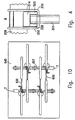
- the said predetermined structure typically comprises a pair of parallel transversely spaced bars (7) and (107) mounted onto the roof (640) of a vehicle via mounting brackets (71) at each end thereof.
- the mounting brackets (71) are typically mounted to the rain gutters of the vehicle, or where the vehicle lacks rain gutters to suitable mounting points on the roof, in a similar manner, for example, as currently known for mounting roof racks, ski carriers and the like.
- the modular bicycle carrier system enables several bicycles 600 to be simultaneously carried on a vehicle roof top (640), in a staggered longitudinal configuration.
- each bicycle handlebar (209) is gripped at its two ends by a pair of first gripping units (15) which are connected to longitudinal bar extensions (500), which are in turn attached to one of the transversal bars (7).
- the corresponding seat or seat post is attached to a second gripping unit (25) which is connected to the other transversal bar (107).
- the first gripping units (15) of a bicycle are adapted for coupling to a third gripping unit, wherein the third gripping unit is in fact a first gripping unit used for gripping a front portion of an adjacent bicycle, the third gripping unit thus being adapted for gripping one end of the handle bar of the adjacent bicycle.
- the first gripping units (15) are adapted for coupling with the third gripping unit by being mounted onto the transverse bar (7) by means of longitudinal bar extension (500), which longitudinally displaces the clamping position of the first clamping unit with respect to transverse bar (7), but at the same time enables a third gripping unit to be coupled thereto, the third coupling unit being longitudinally displaced with respect to the bar (7) in the opposite direction.
- the first gripping means (15) of this embodiment comprises coupling means in the form of said extension (500), for coupling to a first gripping means (15) of an adjacent bicycle.
- the rear gripping unit (25) may also be adapted to be mounted onto the rear transverse bar (107) in a correspondingly staggered manner in order to enable the rear portions of adjacent bicycles to be secured thereon.
- the degree of fore- or aft- staggering of such rear gripping units (25) will depend on the wheelbase of the bicycles themselves.
- One such rear gripping unit (25) is described below with respect to figure 9
- the said bicycle carrier system is modular, and thus in this embodiment a user may decide to mount two said first gripping means (15) to all inboard extensions (500), while only mounting one first gripping means (15) to the outboard extensions (500).
- some or all the extensions (500) may be used for mounting only a single first gripping unit (15).
- the first gripping units need not all be of the same type, but only adapted in pairs to be mutually coupled via corresponding said extension (500).
- one form of said first gripping means (15) used in conjunction with extension (500) comprises a handlebar gripping unit (350), which is mountable at one longitudinal end of the extension (500).
- the handlebar gripping unit (350) comprises a support (314), preferably with padding (309), for seating the bicycle handlebar (209) in it.
- Handle (301) has a transversal hinge (328) for selectively placing it in one of the notches (392) or (393) of extension (500).
- the fourth clamping member (310) in this case a curved or flexible rectangular ring, is attached at its first end (370) to handle (301), and its second end (365) is selectively placed in one of the notches (362) or (372) of extension (500).
- handle (301) is first turned clockwise (referring to the left-hand handlebar gripping unit (350) of Figure 3) until hinge (328) is released from the notch (392) or (393) in which it was placed, and then separated in a clockwise direction from bar 200 for allowing the placement of the handlebar on support (314).
- a U-shaped screw (260), and nuts (240) attach said extension (500) to the transversal roof top bar (7), shown in cross-section.
- the handlebar gripping unit (250) is attached to the extension (500) in two locations, by a transversal hinge (203), and by a vertical rod (206), which is in turn attached to the extension (500) by a rotating nut (248) and by two screws (247).
- Hinge (203) secures the third clamping member (210) of gripping unit (250) to the extension (500), but still allows it to rotate to some degree about hinge (203).
- the third clamping member (210) which may be at least partially flexible, covers the upper portion of the handlebar (209) that is not covered by the internal surface of support (214).
- the third clamping member (210), further has a notch (not shown) at its end (219), for containing rod (206).
- the handle (201) is hingedly connected to rod (206) by hinge (221), and its surface (222) is eccentric with respect to hinge (221). Therefore, the handle (201) essentially has two positions. In order to grip a bicycle handlebar (209), the handle (201) is turned fully counterclockwise, thereby releasing any pressure from member (210), and allowing its separation from rod (206), and its turning clockwise.
- handlebar (209) is placed on the support (214), the third clamping member (210) is turned counterclockwise, merging with rod 206 by the notch at end (219), and handle (201) is fully turned clockwise, actuating a pressure on the third clamping member (210), and locking the handlebar (209) by the gripping unit (250).
- the rod (206) is preferably threaded at its attachment with nut (248), for enabling the adjustment of the pressure that handle (201) acts on the third clamping member (210).
- the handle gripping units (350) or (250) can have several variations in ways well known to those skilled in the art.
- parts of it can be made of, or include, different materials such as plastic, metal, or leather.
- the flexible ring (310) can be replaced by a leather belt with a buckle at its end (365). Those variations are within the scope of the invention.
- each bicycle is also secured by means of a second gripping unit (25), which clamps the corresponding seat, seat stay or seat post of the bicycle to the other transversal bar (107).
- a second gripping unit 25
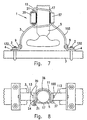
- said second gripping unit (25) comprises a seat post gripping unit (1).
- Said seat post gripping unit (1) is attached to a transversal bar (107) of the roof rack by two U-shaped screws and nuts (2) and (132) respectively, similar to the screw (260) which is shown in Figure 5, for example.
- the L-shaped members (4) are attached to the left supporting bar (3) and to the right supporting bar (103) by hinge pins (9), thereby providing an arrangement having some flexibility and the capability to absorb shocks, and the adaptation of the unit to different sizes of bicycles, when necessary.
- the gripping of the seat post (5) is provided by the gripping portion (10).
- First clamp (11) which has a generally U-shaped cross-section, is fixed to the left supporting bar (3) by a hinge pin (13) and to the right supporting bar (103) by hinge pin (113). It generally covers at least 50% of the perimeter of the seat post (5), preferably about 60-80%.
- Second clamp (17) is hingedly attached to the clamping handle (20), at the hinge location (24), and it closes the opening of the U-shaped cross-section of the first clamp (11), thereby covering essentially the rest of the perimeter of the post which is not covered by the first clamp (11).
- At least one pad (36) is also provided, at the internal surface of either the first clamp, the second clamp, or both, for enabling a flexible grip of the seat post, and for providing shock absorbance, and possibly for eliminating damage to the paint of the seat post (5).
- Handle (20) has two states, an "inoperative state” in which the handle (20) is at least partially turned counterclockwise, and an "operative state” wherein the handle (20) is turned fully clockwise.
- the first clamp has a clasp (37).
- the mounting of the seat post (5) is carried out as follows: the second clamp (17) is separated from the clasp (37) of the first clamp, and is turned clockwise, thereby producing an opening through which the seat post is entered, gripped by the internal surface of the first clamp (11).
- the second clamp (17) is turned counterclockwise, placed beyond the clasp (37), as shown in Figure 8.
- the handle (20) is fully turned clockwise, resulting in a strong, "geometrical” locked grip of the seat post (5) by the term “geometrical” it is meant here that the device includes a part, such as a handle, that when rotated about a hinge in an eccentric location has two states, a "released” state and a “locked” state.
- the seat post gripping unit (1) provides a strong grip of the bicycle seat post, with a flexibility, and shock absorbance, which is needed during the vehicle movement and the bicycle transportation. Furthermore, it also enables a fast and easy coupling and releasing of the bicycle.
- the seat post gripping unit (1) can have several variations, other than the one shown in Figures 7 and 8, which are also within the scope of the invention.
- it may have a "geometric" lock structure similar to the one used in the handlebar gripping unit of Figure 3 which is discussed hereinbefore in detail.
- said second gripping unit (25) may comprise a seat gripping unit (400) for a seat or a seat post of a bicycle as shown in Figure 9, for example.
- the seat gripping unit (400) is attached by a U-shaped retainer (407) and corresponding nuts (401) to a transversal bar (107) of the predetermined structure.
- the unit further comprises a support (402) for the seat, on which the seat of the bicycle is placed, and a belt (403) with buckle (404).
- a soft padding (410) covers the support (402), for providing a protection to the seat and some shock absorption.
- the padding (410) is preferably higher than the nuts (401) and the ends of the retainer (407), for preventing possible damage to the bicycle seat, and has two cylindrical holes for the said screw (407) and nuts (401).
- the seat is placed on the support (401) with padding (410), and is then gripped in a conventional manner by the (403), using the buckle (404) for tightening.
- the seat gripping unit (400) may be adapted for enabling the seat of the bicycle to be mounted onto said transverse bar (107) in a longitudinally staggered manner in a number of ways.
- the seat may be mounted onto the seat gripping unit (400) longitudinally displaced from the centre thereof in a forwardly or rearwardly direction, within limits, while ensuring securement thereto.
- the U-shaped retainer (407) may be secured to said seat gripping unit (400) via pairs of longitudinal slots or via a plurality of pairs of orifices, thereby enabling a degree of relative displacement between the two in a longitudinal direction.
- each of the bicycles carried on said carrier (10) may be clamped at the rear portion thereof by either a said seat post gripping unit (1) or a said seat gripping unit (400), though typically all the bicycles in the carrier (10) are clamped by the same type of said second gripping unit (25).
- a plurality of bicycles may be carried on the roof of a vehicle, wherein pairs of bicycles may be coupled together and secured by said carrier (10) in staggered parallel back-to-front arrangement.
- each bicycle handlebar (209) may be gripped at its two ends by a pair of first gripping units (15) which are mounted to one of the transversal bars (7) or (107).
- the corresponding seat or seat post of each bicycle is secured by a second gripping unit (25) which is coupled to one of the first gripping units (15) that secures one end of the handlebar of the other bicycle of the pair.
- At least one of the first gripping units (15) for gripping a portion of one bicycle is adapted for coupling to a third gripping unit, wherein the third gripping unit is in fact a second gripping unit (25) for gripping a portion of an adjacent bicycle, the third gripping unit being adapted for gripping the rear end, typically the seat or seat post or seat stay of the adjacent bicycle.
- the first gripping units (15) are adapted for coupling with the third gripping unit by having an upper element thereof constitute a part of the corresponding third gripping unit (i.e. the second gripping unit (25) for gripping the rear portion of the adjacent bicycle).
- the first gripping units (15) are adapted for coupling with the third gripping unit by having coupling means for coupling with the corresponding third gripping unit (i.e. the second gripping unit (25) for gripping the rear portion of the adjacent bicycle).
- the said first gripping unit (15) may thus be coupled to a second gripping unit (25), either permanently, semi-permanently, or releasably, to provide a universal clamp that may be used to clamp the front portion and/or the rear portion of a bicycle, for securement to a position on a structure.
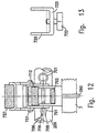
- Figures 10 to 13 illustrate a second embodiment of the present invention in which a universal bicycle clamp, designated by the numeral (100), comprises:
- the universal clamp (100) While such a universal clamp (100) may be used for clamping the front portion only or the rear portion only of a bicycle to said predetermined structure, the universal clamp (100) is typically adapted for simultaneously clamping a front portion of a first bicycle and a rear portion of a second bicycle.
- the first griping unit (15) is adapted for releasably gripping and securing a front portion of the first bicycle; and the second griping unit (25) is adapted for releasably gripping and securing a rear portion of the second bicycle.
- the said universal clamp (100), according to the second embodiment of the present invention, is particularly adapted for clamping the front portion of a bicycle, such as one side of the handlebar (209), and/or the rear portion of another bicycle, such as the seat, seat stay or any other rear portion of the bicycle.
- the said universal clamp (100) may be clamped on an upper surface of a vehicle, in particular a roof top (640) of said vehicle, via either one of said transverse bars (7) or (107), which is in turn mounted onto the vehicle, as hereinbefore described.
- the universal clamp (100) is suitably mounted to the transverse bar (7), say, by means of any suitable fastening mechanism, particularly of the quick-release type, and in the preferred embodiment the fastening mechanism comprises a U-shaped retainer (260) having threaded free ends onto which nuts (240) may be screwed to secure the bar (7) with respect to the universal clamp (100).
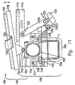
- the first gripping unit (15) comprises a front gripping unit (120) comprising a lower arm (700), typically having a U-shaped transverse section, and the retainer (260) is typically secured thereto.
- An upper arm (710) also typically having a U-shaped transverse section, is hingedly connected to said lower arm (700) by a hinge (711) cooperating with a notch (705) at corresponding first ends of the upper and lower arms.
- the hinge (711) and notch (705) enable the upper arm (710) to be rotated towards and away from the lower arm (700), respectively defining a closed position, wherein the upper arm (710) and the lower arm (700) are in substantially parallel arrangement, and an open position, in which the front portion of a bicycle, typically a side of the handlebar, may be inserted or removed from the first gripping unit.
- the said hinge (711) and notch (705) are adapted for enabling the said upper arm (710) and said lower arm (70)0 to be detached one from the other when desired, when the said universal clamp (100) is not in clamping mode, i.e., is not clamping a bicycle.
- the upper arm (710) and the lower arm (700) comprise opposed recesses, (752) and (742), respectively, adapted to grippingly hold therebetween a portion of a handlebar (209) of a bicycle when said upper arm (710) and said lower arm (700) are in the closed position.
- the recesses (752), (742) typically comprise suitable pads, (712), (702) respectively, to prevent damage to the handlebar and to dampen vibrations.
- the front gripping unit (120) further comprising locking means for releasably locking said upper arm (710) with respect to said lower arm (700).
- Figures 11 to 13 show a number of different locking means simultaneously for locking the upper arm (710) and lower arm (700) together, in practice only one such locking means, or indeed one of any number of suitable locking means including those described with reference to Figures 1 to 9, need be used, mutatis mutandis .
- the free ends of the upper arm (710) and the lower arm (700) substantially overlap and comprise aligned apertures.
- a fast removal pin (701) is insertable via a first end thereof through the aligned apertures, to hold the free ends of the arms together.
- the pin (701) comprises a stop at a second end thereof to limit extent of insertion of said through the apertures, and the pin (701) further comprises a longitudinal slit (709) at said first end thereof and comprising a wedge-shaped stop (708) associated with each half of the said pin (701) divided by the slit, (709).
- This arrangement enables the halves of said first end of the pin (701) to be urged together to reduce the transverse cross-section of the wedges (708) to less than that of the aligned apertures and thus enable first end of the pin (701) to pass through the aligned apertures.
- the halves of the pin end are resilient and spring back to enable the said wedge-shaped stops 708 to lock said pin (701) with respect to the aligned holes.
- the locking means may comprise a U-shaped bar (720) having a base joined to a pair of arms, said U-shaped bar being hingedly joined at the free arms thereof by a hinge (721) to the free end of said upper arm (710).
- the said U-shaped bar (720) is adapted for reversibly swinging from a locking position in which the said base (723) of the U-shaped bar (720) is in juxtaposition with or superposed with respect to the underside of said free end of said lower bar (700), to an unlocked position wherein the base (723) of the U-shaped bar (720) is spaced from said free end of said lower arm (720).
- the base (723) comprises a bolt arrangement (722) capable of being received in a complementary socket (703) disposed on the underside of said lower arm for locking said U-shaped bar onto said lower arm.
- the locking means comprises a ratchet arrangement comprising a U-shaped clamp (725), hinged at the free arms thereof to the free end of said upper arm (710).
- the base of the U-shape clamp (725) in this embodiment comprises a detent, pawl or suitable stop (726) complementary to any one of a plurality of teeth or notches (704) comprised on the free end of said lower arm (700).
- the U-shaped clamp (725) is capable of swinging from a locking position in which the stop (726) of the U-shaped bar is engaged with any one of said teeth (704) of said lower bar (700), to an unlocked position wherein the base (726) of the U-shaped clamp (725) is spaced from said free end of said lower arm (700).
- the upper arm (710) is brought towards the lower arm (700) against the elastic resistance of the pads (712), (702), when a side of the handle bar (209) is clamped therebetween.
- the second gripping unit (25) may be coupled to the first gripping unit (15) in a permanent, semi-permanent or releasable manner.
- the second gripping unit is coupled to the first gripping unit, even if only one of the two is to be used at any one time.
- the second gripping unit (25) comprises rear gripping means (140) for clamping the rear portion of a bicycle to said predetermined structure via said first gripping means (15) coupled thereto.
- the rear gripping means (140) comprises a belt (732) having a suitable buckle arrangement comprising buckles (not shown) at its two ends or at only one end thereof, for securing the rear portion of a bicycle onto the upper arm (710).
- the front gripping unit (120) is adapted for coupling to the rear gripping unit (140) in that the upper arm (710) of the front gripping unit (120) is also part of the rear gripping unit (140) itself, and in that it comprises, means for securing the belt (732) thereto, for example, a notch (714) as described hereinbelow.
- the buckle arrangement is adapted for engaging and securely holding together the two ends of said belt, the said belt (732) being securably attached to said upper arm (710) of said front gripping unit (120), for example by threading the same through notch (714) in upper arm (710).
- the said buckle arrangement comprise suitable tensioning means capable of selectively tensioning said belt for securing and locking the said rear portion of a bicycle, and for releasing the tension of the belt, thereby allowing the dismounting of the said rear portion of a bicycle from the second gripping unit.
- the belt (732) secures the seat of the bicycle, and the upper arm (710) further comprises a soft pad (713) for seating the bicycle seat thereupon.
- said rear gripping unit (140) is independent of the front gripping unit (120), and comprises a belt (732) having a similar buckle arrangement at its two ends(not shown), the said belt being securably attached to a top arm (730).
- the front gripping unit (120) is thus adapted for coupling to the rear gripping unit (140) in that the former enables the top arm (730) to be hingedly attached by means of hinge (731) to said upper arm (710) of said front gripping unit (120).
- the belt (732) is secured to the top arm (730) for example by threading the same through notch (734) in top arm (730).
- the buckle arrangement is adapted for engaging and securely holding together the two ends of said belt, and comprises suitable tensioning means capable of selectively tensioning said belt for securing and locking the said rear portion of a bicycle and for releasing the tension of the belt, thereby allowing the dismounting of the said rear portion of a bicycle from the second gripping unit.
- the said top arm (730) comprises pad (737), and the rear end of a bicycle, preferably the seat thereof, is held securely between the pad (737) and the belt (732).
- the top bar (730) may be rotated over a limited arc about hinge (731) in order to compensate for the range of possible seat-to-seat post angles.
- three said universal clamps (100) may be used for clamping each bicycle onto the desired location, in which one said universal clamp (100) clamps the rear portion of said bicycle via said corresponding second gripping unit (140), and wherein the remaining two said universal clamps (100) clamp the front portion of the said bicycle via said corresponding first gripping units (120) thereof. It is also possible to clamp a bicycle with only two said universal clamps (100), one for clamping at the rear portion of the bicycle via said corresponding second gripping unit (140), and wherein the remaining said universal clamps (100) clamps only one side of the handlebar (209), for example, via said corresponding first gripping units (120) thereof.
- the second embodiment may also be used for simultaneously clamping a first bicycle and a second bicycle onto any suitable surface, in particular an upper surface of a vehicle, wherein four said universal clamps (100) are used for clamping each pair of bicycles onto the desired structure: a first said universal clamp (100) simultaneously clamps a front portion of said first bicycle and a rear portion of said second bicycle, wherein a second said universal clamp (100) simultaneously clamps a rear portion of said first bicycle to a front portion of said second bicycle, and wherein a third and a fourth said universal clamps (100) respectively clamp the front portion of said first bicycle and the front portion of the said second bicycle.
- the last two said universal clamps (100) are optional, and only the first two universal clamps are strictly required to clamp a pair of bicycles together onto said structure.
- the universality of the universal clamp (100) increases simplicity of installation and use, and substantially simplifies the logistics for supplying such universal clamps (100).
- Another major advantage of the universal clamp (100) is that by simply adding a fourth universal clamp (100), a second bicycle may be clamped as a pair together with the first bicycle and secured onto the upper surface of a vehicle, as illustrated in Figure 10. This is accomplished by clamping the rear end of one bicycle and the front end of the other bicycle with one universal clamp (100), and vice versa for a second universal clamp (100), the remaining two universal clamps (100) being used to clamp the free sides of the handlebars of the two bicycles.
- the second embodiment may be modified for enabling a plurality of bicycles to be clamped together in a cluster, rather than just in pairs, and secured to a structure on the roof top of a vehicle, providing a more compact packing of the bicycles.
- the first gripping unit (120) of the universal clamp (100) is mounted onto a said longitudinal extension (500) in a manner similar to that described herein for the first embodiment of the invention, mutatis mutandis, rather than directly to the transverse bars (7) or (107).
- the universal clamp (100) to be coupled to another front gripping unit (120) of an adjacent universal clamp (100) (or indeed to a front gripping unit (250) or (350) of the first embodiment), and thus the front gripping unit (120) is effectively coupled to both a rear gripping unit (140) and to another front gripping unit (120), enabling three bicycles to be secured to the same location on the predetermined structure, i.e., the transverse bar (7) or (107).
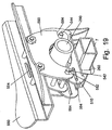
- a first gripping unit (15) comprises a front gripping unit (510) for clamping one end of a handle bar (209) and securing it to the structure, in particular said transverse bar (7) or (107).
- front gripping unit (510) comprises a lower longitudinal member (512) adapted for mounting onto said structure, and thus preferably comprises a U-shaped retainer (260) for mounting onto transverse bar (7) or (107) via bolts (240), in a similar manner as hereinbefore described for the first and second embodiments, mutatis mutandis .
- the lower member (512) has a substantially U-shaped transverse cross-section, and thus comprises a horizontal bracket (508) integrally joined to two vertical flanges (509).
- the horizontal bracket (508) is seatable onto said transverse bars (7) or (107), and comprises a pair of apertures (not shown) for enabling the free ends of the U-shaped retainer (260) to be passed therethough so as to screw the bolts (240) thereto and thus secure the front gripping unit (510) to the transverse bar (7) or (107).
- the front gripping unit (510) further comprises an articulated upper longitudinal member (514), also typically comprising a U-shaped transverse profile.
- the articulated upper longitudinal member (514) comprises an upper clamping member (519) comprising an upper bracket (511) integrally joined to two downwardly depending vertical flanges (513), hingedly joined at a first longitudinal end thereof to an intermediate member (516) via pin (520), which is in turn hingedly joined at the other end thereof to a locking lever (518) via pin (522).
- the locking lever (518) is itself hingedly joined to a first end of the lower member (512) via pins (524).
- the second end (532) of said upper longitudinal member (514) comprises a pair of hook-shaped recesses (515) for hooking onto pin (517) comprised at the second longitudinal end (530) of the lower member (512).
- the said articulated upper longitudinal member (514), and locking member (518) are thus rotatable as a unit about pins (524) with respect to the lower member (512), enabling the second end (532) of the upper member (514) to be selectively brought into proximity with and distanced from the second end (530) of the lower member (512).
- the upper longitudinal member (514), including said pin (520) and the lower member (512) are waisted or recessed in their facing center sections so as to enable a handlebar (209) to be accommodated between them when locked together as shown in Figure 16.
- the said upper member (514) and the lower member (512) comprise cushioning pads (507) for protecting the handle bar (209) against damage from contact with the upper flanges (513) and lower flanges (509), and also help to dampen vibration.
- a strengthening strut (531) may be joined to flanges (513).
- upper longitudinal member (514) including said upper clamping member (519), said pin (520) and said intermediate member (516) may be a unitary flexible member made from a flexible material such as a suitable plastic material, for example, that in the unstressed state assumes a shape similar to that of upper clamping member (519) and said intermediate member (516) when in the closed position shown in Figure 16.
- an upper member (514) is such as to enable it (in the open position shown in Figure 15, for example) to overshoot the second end (530) of the lower member (512) and to engage the same, either in a manner similar to that described above or with the added difference that the pin (517) is comprised in the upper flexible member, and the recesses (515) are comprised in the lower member (512), mutatis mutandis .
- the upper and lower members may be engaged using a suitable quick release engagement mechanism, and such a suitable quick-release engagement mechanism is also preferably adjustable, thereby taking account of a wide range of handlebar diameters, for example.
- the second gripping unit (25) comprises a rear gripping unit (550) for mounting and securing the seat of a bicycle thereto.
- the rear gripping unit (550) comprises a horizontal bracket (558) integrally joined to two vertical flanges (559).
- the horizontal bracket (558) is seatable onto said transverse bars (7) or (107), and comprises one pair or a number of pairs of apertures, (not shown) for enabling the free ends of a U-shaped retainer (260) to be passed therethough so as to enable screwing of the bolts (240) thereto and thus secure the rear gripping unit (550) to the transverse bar (107) or (7).
- a number of longitudinal slots (563) are provided in lieu of the apertures on said horizontal bracket (558), thereby enabling the relative longitudinal position of the rear gripping unit (550) with respect to the transverse bar (107) or (7) onto which it is mounted to be adjusted, to take account of the range of wheelbase dimensions of different bicycles.
- a pair of wings (562) are dihedrally joined, preferably integrally, to the vertical flanges (559), the wings (562) being suitable shaped for providing a seat for the bicycle seat to rest on.
- said wings (562) comprise cushioning pads (not shown) for protecting the bicycle seat and for dampening vibration.
- the rear gripping unit (550) further comprises a belt (not shown) having a suitable buckle arrangement comprising buckles (not shown) at its two ends or at only one end thereof, for securing the rear portion of a bicycle onto the rear gripping unit (550).
- the buckle arrangement is adapted for engaging and securely holding together the two ends of said belt, the said belt being securably attached to said vertical flanges (559) of said rear gripping unit (550), for example by threading the belt through notches (554) formed in said vertical flanges (559).
- the said buckle arrangement preferably comprises suitable tensioning means capable of selectively tensioning said belt for securing and locking the said rear portion of a bicycle, and for releasing the tension of the belt, thereby allowing the dismounting of the said rear portion of a bicycle from the second gripping unit (550).
- the belt secures the seat of the bicycle.
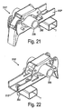
- the said front gripping unit (510) may be coupled to a rear gripping unit (550) by means of a coupling bracket (590)
- the said coupling bracket (590) is in the form of a pair of vertical flanges which may be releasably bolted to the said rear gripping unit (550), enabling the latter to be releasably engaged onto a front gripping unit (510), in which case such a rear gripping unit (550) would of course dispense with the U-shaped retainer (240), since it is not to be mounted directly onto transverse bar (7) or (107).
- the coupling bracket (590) comprises vertically disposed slots (582) at a first end thereof, and horizontally disposed slots at a second end thereof (584).
- the said rear gripping unit (550) is thus adapted for coupling with said front gripping unit (510) in that it comprises apertures (546) on said vertical flanges (559) for enabling bolts (547) to pass therethrough and through the coupling bracket (590) enabling the latter to be securely and releasably locked with respect to the rear gripping unit (550).
- the coupling brackets (590) may be permanently or semi permanently joined to the rear gripping unit (550), say by welding thereto, for example, in which case such a rear gripping unit-coupling unit combination would normally be used solely coupled with the front gripping unit (510), rather than on its own for only coupling a rear portion of a bicycle onto the transverse bars (7) or (107).
- the said front gripping unit (510) is adapted for coupling with said rear gripping unit (550) in that it comprises fore and aft engaging pins (542), (544) for engaging with said coupling bracket (590) via complementary slots (582), (584), respectively.
- the coupling bracket (590) is first mounted onto the rear gripping unit (550) as hereinbefore described. Then, holding the rear gripping unit (550) in orthogonal relationship to the front gripping unit (510), the former is mounted onto the latter by engaging the aft engaging pins (544) into the corresponding complementary slots (584) on said coupling bracket (590), which is then pivoted by about 90° to bring into engagement the fore engaging pins (542) with the slots (582).
- the coupling bracket (590) may be secured and locked in place on the front gripping unit (510) by means of bolts, for example, which are screwable onto the ends of the engaging pins (542) and (544) that protrude from the coupling bracket (590).
- the rear gripping unit (550) is securely locked onto the front gripping unit (510) indirectly by means of the belt and buckle arrangement that is used for securing the rear portion of the bicycle.
- the front gripping unit (510) is also adapted for coupling with the rear gripping unit (550) in that it comprises slots (564) on the vertical flanges (509), similar to said slots (554) on the rear gripping unit (550).
- the belt is securably attached to said vertical flanges (509) of said front gripping unit (510), for example by threading the same through notches (564) in said vertical flanges (509).
- the belt and buckle arrangement is used to secure the rear part of a bicycle to the rear gripping unit-coupling bracket-front gripping unit combination, in a similar manner to that hereinbefore described with reference to the rear gripping unit (550) only, mutatis mutandis .
- This arrangement not only secures the bicycle rear portion onto the rear gripping unit (550), but also results in the rear gripping unit (550) being locked with respect to the front gripping unit (510) via the coupling bracket (590).
- the said front gripping units (510) may be adapted to be secured onto the said transverse bars (7) or (107) in a longitudinally staggered configuration.
- fore- and aft-displaced front gripping units, (510") and (510'), respectively are similar to the said front gripping units (510) as hereinbefore described, except that the said lower longitudinal member (512) is replaced by corresponding extended lower longitudinal members (512") and (512'), respectively, mutatis mutandis, which comprise longitudinal extensions.
- the lower longitudinal member (512") extends from the said second end (530) thereof in an aft direction, and the rearmost portion thereof is adapted for mounting onto said structure, and thus preferably comprises a U-shaped retainer (260) for mounting onto transverse bar (7), say, via bolts (240), in a similar manner as hereinbefore described for the preferred embodiment, mutatis mutandis .
- the lower longitudinal member (512') extends in an forward direction from the said second end (530) thereof, and the foremost portion thereof is adapted for mounting onto said structure, and thus preferably comprises a U-shaped retainer (260) for mounting onto transverse bar (7), say, via bolts (240), in a similar manner as hereinbefore described for the preferred embodiment, mutatis mutandis .
- the said fore- and aft-displaced front gripping units, (510") and (510') may be in fact identical, and differing only in the direction in which they are actually mounted onto the said transverse bars (7) or (107).
- the said fore- and aft-displaced front gripping units, (510") and (510'), may be mounted onto one of said transverse bars, say (7), in spaced pairs, enabling pairs of bicycles to be separately secured onto the transverse bars (7) and (107) in a compact manner, as illustrated in Figure 20, in a staggered but front-to-front parallel configuration.
- the rear portions of bicycles which are secured at their front portions by means of said fore- or aft-front gripping units, (510") or (510'), may be secured, for example, by a said rear gripping unit (550) directly mounted onto transverse bar (107) as hereinbefore described, or alternatively by means of a rear gripping unit (550) coupled to a front gripping unit (510) which is directly mounted onto the transverse bar (107).
- a said rear gripping unit (550) directly mounted onto transverse bar (107) as hereinbefore described, or alternatively by means of a rear gripping unit (550) coupled to a front gripping unit (510) which is directly mounted onto the transverse bar (107).
- Each one of the said fore- or aft-front gripping units, (510") or (510') is adapted for coupling with a said rear gripping unit (550) in a similar manner to said front gripping unit (510), as hereinbefore described mutatis mutandis .
- the said front gripping unit (510) of the preferred embodiment may be alternatively or additionally coupled with another said front gripping unit (510) to provide a double front gripping unit (510"').
- a longitudinal bridging member (599) is joined to two said front gripping units (510) in back-to-back configuration, such that the said second ends (530) of the corresponding lower longitudinal members (512) are joined to the ends of said longitudinal bridging member (599).
- the said adjacent lower longitudinal members are integrally joined to the said longitudinal bridging member (599) in a single element to form a double lower member (512"'), as illustrated in Figure 23, though the adjacent lower longitudinal members may be otherwise joined to the bridging member (599) permanently, for example by welding, or releasably, with the use, for example, or suitable mounting brackets (not shown).
- the double front gripping unit (510"') is adapted for mounting onto said structure, and thus the said bridging member (599) preferably comprises a U-shaped retainer (260) for mounting onto transverse bar (7) or (107) via bolts (240), in a similar manner as hereinbefore described for the single front gripping unit (510) of the preferred embodiment, mutatis mutandis .
- the said double front gripping unit (510"') may be mounted onto one of said transverse bars, say (7), enabling a pair of bicycles to be secured as a pair onto the transverse bars (7) and (107) in a compact manner, in a staggered front-to-front parallel relationship, similar to that shown on Figure 2 for the first embodiment.
- the rear portions of bicycles which are secured at their front portions by means of said double front gripping unit (510"') may be secured, for example, by a said rear gripping unit (550) directly mounted onto the second transverse bar (107) longitudinally staggered if necessary via said slots (563) as hereinbefore described or alternatively by means of a rear gripping unit (550) coupled to a front gripping unit (510).
- a more compact system may be provided by coupling a rear gripping unit (550) to one of said fore- or aft-front gripping units, (510") or (510'), or to another said double front gripping unit (510"') directly mounted onto the transverse bar (107).
- Each said double-front gripping units (510"') may be further adapted for coupling with a said rear gripping unit (550) in a similar manner to said front gripping unit (510), as hereinbefore described mutatis mutandis .
- one said double front gripping unit (510"') with a coupled rear gripping unit (550) secures the seat of bicycle B and the handle bars of adjacent bicycles A and C; another said double front gripping unit (510"') with a coupled rear gripping unit (550) secures the seat of bicycle C and the handle bars of adjacent bicycles B and D; a third said double front gripping unit (510"') with a coupled rear gripping unit (550) secures the seat of bicycle D and the handle bars of adjacent bicycles C and E.
- One said aft-front gripping unit (510") secures one handle bar of bicycle A, and another said aft-front gripping unit (510") secures one handle bar of bicycle E.
- the rear gripping units (550) may also be mounted to the other transverse bar (107) in a staggered manner by bolting the said U-shaped retainer (260) to the rear gripping unit (550) in a suitable point along an appropriate one of the said plurality of slots (563).
- the gripping units of the bicycle carrier of the invention and their parts can be made from different materials, such as metal, plastic, or leather or similar conventional materials known in the art, or indeed advanced materials such as carbon fibre or other composites, for example. Furthermore, the different components comprised in the first and second gripping units may be modified from the precise forms described herein to maximise the advantages arising from using different materials.
Landscapes
- Engineering & Computer Science (AREA)
- Mechanical Engineering (AREA)
- Fittings On The Vehicle Exterior For Carrying Loads, And Devices For Holding Or Mounting Articles (AREA)
- Automatic Cycles, And Cycles In General (AREA)
Abstract
Description
Claims (75)
- A modular bicycle carrier system for releasably clamping at least one bicycle (600) onto a predetermined structure, comprising :characterised in thatat least one first gripping unit (15) adapted for releasably gripping a first portion of a bicycle with respect to said structure;at least one second gripping unit (25) adapted for releasably gripping a second portion of a bicycle with respect to said structure,
at least one of said first gripping unit (15) or said second gripping unit (25) is further adapted for coupling with at least one third gripping unit for releasably gripping a portion of another bicycle (600), such as to enable a said third gripping unit to be releasably secured with respect to said structure via said first gripping unit (15) or via said second gripping unit (25), respectively. - A modular bicycle carrier system as claimed in claim 1, wherein said structure comprises longitudinally spaced first and second transverse members (7, 107) comprising mounting means (71) for mounting said transverse members onto an upper portion of a vehicle.
- A modular bicycle carrier system as claimed in claim 2, wherein said upper portion of a vehicle is the roof (640) of a vehicle.
- A modular bicycle carrier system as claimed in claim 1, wherein said at least first gripping unit (15) and said second gripping unit (25) are adapted for clamping said at least one bicycle in vertically inverted configuration.
- A modular bicycle carrier system as claimed in claim 2, wherein said at least one first gripping unit (15) is mountable onto said first transverse member (7) via first securing means.
- A modular bicycle carrier system as claimed in claim 2, wherein said second gripping unit (25) is mountable onto said second transverse member (107) via second securing means.
- A modular bicycle carrier system as claimed in claim 4, wherein said first gripping unit (15) is adapted for clamping a front portion of a bicycle (600).
- A modular bicycle carrier system as claimed in claim 7 wherein said front portion comprises a side of a bicycle handlebar (209).
- A modular bicycle carrier system as claimed in claim 4, wherein said second gripping unit (25) is adapted for clamping a rear portion of a bicycle (600).
- A modular bicycle carrier system as claimed in claim 9, wherein said rear portion comprises the seat of a bicycle (600).
- A modular bicycle carrier system as claimed in claim 9, wherein said rear portion comprises the seat post of a bicycle (600).
- A modular bicycle carrier system as claimed in claim 8, wherein said first gripping unit (15) is adapted for coupling with at least one third gripping unit, and wherein said third gripping unit is adapted for clamping the front portion of another bicycle.
- A modular bicycle carrier system as claimed in claim 12, wherein said front portion comprises a side of a bicycle handlebar (209).
- A modular bicycle carrier system as claimed in claim 8, wherein said first gripping unit (15) is adapted for coupling with at least one third gripping unit, and wherein said third gripping unit is adapted for clamping the rear portion of another bicycle (600).
- A modular bicycle carrier system as claimed in claim 14, wherein said rear portion comprises a seat of a bicycle (600).
- A modular bicycle carrier system as claimed in claim 9, wherein the second gripping unit (25) comprises an essentially horizontal support for the bicycle seat, said support being attached to the said second transverse member (107), and a belt (403) with a buckle (404) connected to said support for gripping and coupling the seat of the bicycle to said horizontal support.
- A modular bicycle carrier system as claimed in claim 16, wherein said support is padded.
- A modular bicycle carrier system as claimed in claim 9, wherein the second gripping unit (25) comprises a gripping portion, and supporting means connecting the gripping portion to the said second transverse member (107).
- A modular bicycle carrier system as claimed in claim 18, wherein the supporting means are flexible, for absorbing shocks resulting from the movement of the vehicle carrying the bicycle (600).
- A modular bicycle carrier system as claimed in claim 19, wherein the gripping portion (10) comprises a first clamping element (11) having an essentially U-shaped cross-section for containing a portion of the perimeter of the bicycle seat post (5), a second clamping element (17) for completing containment of substantially the whole perimeter of the seat post (5), and a handle (20) for tensioning, securing and locking the said clamping elements around the seat post (5), or releasing the same.
- A modular bicycle carrier system as claimed in claim 20, wherein the supporting means comprises at least one supporting bar (3), (103) connected at its first end to said second transverse member, and at its second end to the seat post gripping portion.
- A modular bicycle carrier system as claimed in claim 12, wherein said first gripping unit (15) is adapted for coupling to said third gripping unit by means of a first portion of a longitudinal extension member (500), wherein said longitudinal extension member (500) is mounted onto said first transverse member (7) via suitable mounting means, said first gripping unit (15) being secured to said first transverse bar (7) by being mounted to said first portion of said longitudinal extension member (500) in longitudinal spaced relationship with said first transverse member (7).
- A modular bicycle carrier system as claimed in claim 22, wherein said longitudinal extension member (500) comprises a second portion extending from said first transverse member (7) in a direction away from said first gripping unit and wherein said third gripping unit (15) is secured to said first transverse bar (7) by being mounted to said second portion of said longitudinal extension member (500) in longitudinal spaced relationship with said first transverse member.
- A modular bicycle carrier system as claimed in claim 23, wherein said first portion of said longitudinal extension member (500) and said second portion of said longitudinal extension member (500) are integral.
- A modular bicycle carrier system as claimed in claim 24, wherein said longitudinal extension member (500) is mounted onto said first transverse member via suitable U-shaped retainer (260).
- A modular bicycle carrier system as claimed in claim 22, wherein said first gripping unit (15) comprises a vertical rod (206) which is vertically attached at its first end to said first longitudinal extension member (500), a first supporting element for containing a portion of the perimeter of the bicycle handlebar (209), a third clamping element for completing containment of the whole perimeter of the handlebar (209), and a handle hingedly attached to the second end of the said rod, for tensioning, securing and locking the said supporting element with said third clamping element around the bicycle handlebar (209), or releasing the same.
- A modular bicycle carrier system as claimed in claim 22, wherein said first gripping unit (15) comprises a first supporting element attached to the said first longitudinal extension member (500), for containing a portion of the perimeter of the bicycle handlebar (209), a fourth clamping element (310) for completing containment of the whole perimeter of the handlebar (209), and a handle hingedly attached to the said longitudinal extension member and to said fourth clamping element (310), for tensioning, securing and locking the said supporting element with said fourth clamping element around the bicycle handlebar (209), or releasing the same.
- A modular bicycle carrier system as claimed in claim 27 wherein the fourth clamping element (310) of each first gripping unit is a belt having buckles at its two ends, the first buckle being connected to the said longitudinal extension member (500), and the second buckle connected to the handle (301), wherein turning the handle (301) in one direction tensions the belt for securing and locking the said supporting element with said belt around the bicycle handlebar (209), and turning the handle in the other direction releases the tension of the belt, thereby allowing the dismounting of the handlebar from the first gripping unit (15).
- A modular bicycle carrier system as claimed in claim 27, wherein the fourth clamping element (310) of each first gripping unit is a rectangular ring having two ends, the first end being connected to the said longitudinal extension member (500), and the second end being connected to the handle (301), wherein turning the handle (301) in one direction tensions the ring for securing and locking the said supporting element with said ring around the bicycle handlebar (209), and turning the handle in the other direction releases the tension of the ring, thereby allowing the disassembling of the handlebar (209) from the said first gripping unit (15).
- A modular bicycle carrier system as claimed in any one of claims 22 to 29, wherein said third gripping unit is of the same type as said first gripping unit (15).
- A modular bicycle carrier system as claimed in claim 14, wherein said first gripping unit (15) is joined to one of said first or second transverse members (7, 107) by means of a suitable U-shaped clamp (260) adapted for releasably mounting said bicycle clamp to said transverse member.
- A modular bicycle carrier system as claimed in claim 31, wherein said first gripping unit comprises a lower arm (700) and an upper arm (710) hingedly connected to said lower arm (700), at corresponding first ends thereof such as to enable said upper arm (710) to be rotated from a closed position, wherein said first arm and said second arm are in substantially parallel arrangement, to an open position, wherein said upper arm and said lower arm comprise opposed recesses adapted to grippingly hold therebetween a portion of a handlebar (209) of a bicycle (600) when said upper arm (710) and said lower arm (700) are in said closed position, wherein in said open position corresponding free second ends of said upper arm (710) and said lower arm (700) are sufficiently spaced to enable said portion of said handlebar (209) to be inserted into said recesses, said first gripping unit further comprising locking means for releasably locking said upper arm with respect to said lower arm (700).
- A modular bicycle carrier system as claimed in claim 32, wherein upper arm (710) is hingedly connected to said lower arm (700) at corresponding first ends thereof by means of a suitable hinge arrangement adapted for enabling said upper arm (710) to be detached from said lower arm when said bicycle clamp is not in clamping mode.
- A modular bicycle carrier system as claimed in claim 32, wherein in said closed position said free ends of said upper arm (710) and said lower arm (700) substantially overlap and comprise aligned apertures, said locking means comprising a fast removal pin (701) insertable via a first end thereof through said aligned apertures, said pin comprising a stop at a second end thereof to limit extent of insertion of said through said apertures, said pin further comprising a longitudinal slit at said first end thereof and comprising a wedge-shaped stop (708) associated with each half of the said pin divided by said slit, said slit and wedge-shaped stops (708) adapted such as to enable said halves of said first end of the pin to be urged together to reduce the transverse cross-section thereof to less than that of said apertures and thus enable said first end of said pin to pass through said aligned apertures, said halves being resilient and springing back to enable the said wedge-shaped stops to lock said pin with respect to said aligned holes.
- A modular bicycle carrier system as claimed in claim 32, wherein said locking means comprises a U-shaped bar (720) having a base joined to a pair of arms, said U-shaped bar being hingedly joined at the free arms thereof to the free end of said upper arm (710), said U-shaped bar adapted for reversibly swinging from a locking position in which the said base is superposed with respect to the underside of said free end of said lower bar, to an unlocked position wherein the base of the U is spaced from said free end of said lower arm, said base comprising a bolt arrangement capable of being received in a complementary socket disposed on the underside of said lower arm, for locking said U-shaped bar onto said lower arm (700).
- A modular bicycle carrier system as claimed in claim 32, wherein said locking means comprises a ratchet arrangement comprising a U-shaped bar (725) hinged at the free arms thereof to the free end of said upper arm (710) and having a stop on the base thereof complementary to any one of a plurality of teeth (704) comprised on the free end of said lower arm, said U-shaped bar (725) capable of swinging from a locking position in which the stop of the U-shaped bar (725) is engaged with any one of said teeth (704) of said lower bar, to an unlocked position wherein the base of the U is spaced from said free end of said lower arm.
- A modular bicycle carrier system as claimed in claim 32, wherein said recesses (742, 752) are suitably padded.
- A modular bicycle carrier system as claimed in any one of claims 31 to 37, wherein said third gripping unit comprises a belt (732) for releasably securing said rear portion of a bicycle (600), said belt (732) having a suitable buckle arrangement for engaging and securely holding together the two ends of said belt, the said belt being securably coupled to said upper arm (710) of said first gripping unit via a suitable notch (714) comprised therein, and said belt (732) further comprising suitable tensioning means capable of selectively tensioning said belt for securing and locking the said rear portion of a bicycle and for releasing the tension of the belt (732), thereby allowing the dismounting of the said rear portion of a bicycle from the second gripping unit (25).
- A modular bicycle carrier system as claimed in any one of claims 31 to 37, wherein said third gripping unit comprises a belt (732) for releasably securing said rear portion of a bicycle (600), said belt having a suitable buckle arrangement for engaging and securely holding together the two ends of said belt (732), the said belt (732) being securably attached to a top arm via a suitable notch (714) therein, said third gripping unit being coupled to said first gripping unit whereby said top arm is hingedly attached to said upper arm (710) of said first gripping unit, said belt (732) further comprising suitable tensioning means capable of selectively tensioning said belt (732) for securing and locking the said rear portion of a bicycle (600) and for releasing the tension of the belt (732), thereby allowing the dismounting of the said rear portion of a bicycle (600) from the third gripping unit.
- A modular bicycle carrier system as claimed in claim 38, wherein said upper arm (710) comprises a substantially U-shaped transverse cross-section.
- A modular bicycle carrier system as claimed in claim 38, wherein said lower arm (700) comprises a substantially U-shaped transverse cross-section.
- A modular bicycle carrier system as claimed in claim 39, wherein said upper arm (710) comprises a substantially U-shaped transverse cross-section.
- A modular bicycle carrier system as claimed in claim 39, wherein said lower arm (700) comprises a substantially U-shaped transverse cross-section.
- A modular bicycle carrier system as claimed in claims 38 or 40 or 41, for releasably clamping at least one pair of bicycles comprising a first and a second bicycle to a predetermined structure, characterized in that said system comprises, for each said pair of bicycles (600), at least two said first gripping units (15) each coupled to a third gripping unit, wherein one said first gripping unit (15) that is coupled to a third gripping unit is mounted onto said first transverse member (7) and wherein the other said first gripping unit (15) that is coupled to a third gripping unit is mounted onto said second transverse member (107), wherein the said first gripping units on said first and second transverse member (107) respectively secure the front portions of said first and second bicycles (600), and wherein the said third gripping units on said second and first transverse members (7, 107) are the corresponding said second gripping units for respectively securing the rear portions of said first and second bicycles.
- A modular bicycle carrier system as claimed in claims 39 or 42 or 43 for releasably clamping at least one pair of bicycles comprising a first and a second bicycle to a predetermined structure, characterized in that said system comprises providing at least two said first gripping units (15) each coupled to a third gripping unit, wherein one said first gripping unit (15) that is coupled to a third gripping unit is mounted onto said first transverse member (7) and wherein the other said first gripping unit that is coupled to a third gripping unit is mounted onto said second transverse member (107), wherein the said first gripping units on said first and second transverse member respectively secure the front portions of said first and second bicycles (600), and wherein the said third gripping units on said second and first transverse members are the corresponding said second gripping units for respectively securing the rear portions of said first and second bicycles (600).
- A modular bicycle carrier system as claimed in claim 8, wherein said first gripping (15) unit comprises an upper articulated longitudinal member (514) hingedly joined to a lower longitudinal member (512) via a locking member (518), such as to enable the said upper longitudinal member (514) to be selectively pivoted away from said lower longitudinal member (512) to receive therebetween a side of handlebar (209) of a bicycle (600), and towards said lower longitudinal member such as to enable a free end of said upper longitudinal member (514) to releasably engage with a corresponding end of said lower longitudinal member, and wherein said locking member (518) is adapted for locking together said upper longitudinal member with said lower longitudinal member when said free end of said upper longitudinal member is engaged with a corresponding end of said lower longitudinal member (514).
- A modular bicycle carrier system as claimed in claim 46, wherein said articulated member (514) comprises a hooked recess (515) for engaging with a complementary pin (517) comprised in said corresponding end of said lower longitudinal member.
- A modular bicycle carrier system as claimed in claim 8, wherein said first gripping (15) unit comprises an upper flexible member hingedly joined to a lower longitudinal member (512) via a locking member (518), such as to enable the said upper longitudinal member (514) to be selectively pivoted away from said lower longitudinal member (512) to receive therebetween a side of handlebar (209) of a bicycle (600), and towards said lower longitudinal member (512) such as to enable a free end of said upper flexible member to releasably engage with a corresponding end of said lower longitudinal member (512), and wherein said locking member is adapted for locking together said upper flexible member with said lower longitudinal member when said free end of said upper flexible member is engaged with a corresponding end of said lower longitudinal member.
- A modular bicycle carrier system as claimed in claim 48, wherein said flexible member comprises a pin (520) for engaging with a complementary recess comprised in said corresponding end of said lower longitudinal member.
- A modular bicycle carrier system as claimed in claim 47, wherein said first gripping unit (15) is secured to one of said first or second transverse members (7, 107) by means of a suitable U-shaped retainer arrangement (260).
- A modular bicycle carrier system as claimed in claim 49, wherein said first gripping unit is secured to one of said first or second transverse members (7, 107) by means of a suitable U-shaped retainer arrangement (260).
- A modular bicycle carrier system as claimed in claim 9, wherein said second gripping unit (25) comprises a base member for seating thereon a seat of a bicycle and further comprises a belt for releasably securing said rear portion of a bicycle (600), said belt having a suitable buckle arrangement for engaging and securely holding together the two ends of said belt, the said belt being securably coupled to said base member via a suitable notch comprised therein, and said belt further comprising suitable tensioning means capable of selectively tensioning said belt for securing and locking the said rear portion of a bicycle (600) and for releasing the tension of the belt, thereby allowing the dismounting of the said rear portion of a bicycle from the second gripping unit.
- A modular bicycle carrier system as claimed in claim 52, wherein said base member comprises a bottom bracket adapted for seating said second gripping unit on said second transverse member, and two dihedral wing elements (562) joined to said bottom brackets via transversely spaced corresponding vertical flanges.
- A modular bicycle carrier system as claimed in claim 53, wherein said second gripping unit (25) is secured to one of said first or second transverse (7, 107) members by means of a suitable U-shaped retainer arrangement (260).
- A modular bicycle carrier as claimed in claim 54, wherein, said second gripping unit (25) may be secured to one of said first or second transverse members (7, 107) within a range of longitudinal positions relative thereto by means of a plurality of slots adapted for cooperating with said U-shaped retainer arrangement.
- A modular bicycle carrier system as claimed in claim 47 to 55, wherein said first gripping unit comprises fore and aft pins (542, 544) for enabling said first gripping unit to be coupled to a third gripping unit.
- A modular bicycle carrier system as claimed in claim 53 and in claim 56, wherein said first gripping unit (15) is adapted for coupling to said third gripping unit, said third gripping unit constituting a second gripping unit, wherein said third gripping unit further comprises fore and aft apertures for enabling said third gripping unit to be coupled to a said first gripping unit (15).
- A modular bicycle carrier system as claimed in claim 57, further comprising a coupling bracket (590) for coupling said first gripping unit to said third gripping unit.
- A modular bicycle carrier system as claimed in claim 58, wherein said coupling bracket (590) is mountable onto said third gripping unit via said apertures, and wherein said coupling bracket (590) is engageable onto said fore and aft pins (542, 544) of said first gripping unit.
- A modular bicycle carrier system as claimed in claim 59, wherein said first gripping unit comprises a suitable notch (554) at one longitudinal end thereof said belt being securably coupled to said first gripping unit instead of said base member for locking together said first gripping unit and said third gripping unit to the rear portion of a bicycle (600).
- A modular bicycle carrier system as claimed in claim 47, wherein said lower longitudinal member (512', 512") of said first gripping unit comprises a longitudinal extension having securing means for securing said first gripping unit to one of said first or said second transverse members (7, 107) in a longitudinally distanced relationship.
- A modular bicycle carrier system as claimed in claim 61, wherein said longitudinal extension enables said first gripping unit to be selectively mounted to one of said first or said second transverse member (7, 107) in either a forwardly or an rearwardly longitudinal spaced relationship.
- A modular bicycle carrier system as claimed in claim 62, wherein said first gripping unit is secured to one of said first or second transverse members (7, 107) by means of a suitable U-shaped retainer arrangement (260).
- A modular bicycle carrier system as claimed in claims 53 and 63 for releasably clamping at least one pair of bicycles comprising a first and a second bicycle to a predetermined structure in staggered parallel arrangement, characterized in that said system comprises providing at least two said first gripping unit (15), wherein one said first gripping unit (15) is mounted onto said first transverse member (7) for respectively securing the front portion of said first bicycle (600) in a forwardly spaced relationship, and wherein the other said first gripping unit (15) is mounted onto said first transverse member (7) in a rearwardly spaced relationship for securing the front portion of said second bicycle, and further comprises said second gripping units (25) for securing the rear portion of said first and said second bicycles to said second transverse member (107).
- A modular bicycle carrier system for releasably clamping as claimed in claims 54 and 63 at least one pair of bicycles comprising a first and a second bicycle to a predetermined structure in staggered parallel arrangement, characterized in that system comprises providing at least two said first gripping (15), wherein one said first gripping unit (15) is mounted onto said first transverse member for respectively securing the front portion of said first bicycle (600) in a forwardly spaced relationship, and wherein the other said first gripping unit is mounted onto said first transverse member (7) in a rearwardly spaced relationship for securing the front portion of said second bicycle (600), and further comprising providing corresponding said second gripping units (25) for securing the rear portion of said first and said second bicycles to said second transverse member (107).
- A modular bicycle carrier system as claimed in claim 47, wherein said first gripping unit is adapted for coupling to said third gripping unit by means of a longitudinal bridging member (599), wherein said longitudinal bridging member is mounted onto said first transverse member (7) via suitable mounting means, said first gripping (15) unit being joined to said first transverse bar at one longitudinal end thereof, and said third gripping unit being joined to said bridging member at the other end thereof, said third gripping unit constituting another said first gripping unit.
- A modular bicycle carrier system as claimed in claim 66, wherein said longitudinal bridging member (599) is integral with said longitudinal lower members of said first gripping unit and said third gripping unit.
- A modular bicycle carrier system as claimed in claim 67, wherein said longitudinal bridging member (599) is secured to one of said first or second transverse members (7, 107) by means of a suitable U-shaped retainer arrangement (260).
- A modular bicycle carrier system as claimed in claim 66, wherein at least one of said third gripping unit or said first gripping unit is further adapted for coupling to a fourth gripping unit.
- A modular bicycle carrier system as claimed in claim 69, wherein at least one of said first gripping unit or said third gripping unit comprises fore and aft pins (542, 544) for enabling said first gripping unit to be coupled to said fourth gripping unit.
- A modular bicycle carrier system as claimed in claim 53 and in claim 70, wherein at least one of said first gripping unit (15) or said third gripping unit is adapted for coupling to said fourth gripping unit, said fourth gripping unit being of the same type as said second gripping unit, wherein said fourth gripping unit further comprises fore and aft apertures for enabling said fourth gripping unit to be coupled to a said first gripping unit (15).
- A modular bicycle carrier system as claimed in claim 71, further comprising a coupling bracket (590) for coupling at least one of said first gripping unit or said third gripping unit to said fourth gripping unit
- A modular bicycle carrier system as claimed in claim 72, wherein said coupling bracket (590) is mountable onto said fourth gripping unit via said apertures, and wherein said coupling bracket is engageable onto said fore and aft pins (542, 544) of at least one of said first gripping unit or said third gripping unit.
- A modular bicycle carrier system as claimed in claim 73, wherein at least one of said first gripping unit or said third gripping unit comprises a suitable notch at one longitudinal end thereof said belt being securably coupled to said first gripping unit or said third gripping unit, respectively, instead of said base member for locking together said first gripping unit or said third gripping unit, respectively, and said fourth gripping unit to the rear portion of a bicycle (600).
- A modular bicycle carrier system as claimed in any one of claims 1 to 74, wherein at least one of said first gripping unit or said second gripping unit or said third gripping unit is a "geometrical lock" type unit.
Applications Claiming Priority (5)
| Application Number | Priority Date | Filing Date | Title |
|---|---|---|---|
| IL12850299 | 1999-02-11 | ||
| IL12850299 | 1999-02-11 | ||
| IL13180499 | 1999-09-08 | ||
| IL13180499A IL131804A0 (en) | 1999-02-11 | 1999-09-08 | Improved bicycle carrier for top of vehicle |
| PCT/IL1999/000697 WO2000047450A1 (en) | 1999-02-11 | 1999-12-23 | Bicycle carrier |
Publications (2)
| Publication Number | Publication Date |
|---|---|
| EP1150863A1 EP1150863A1 (en) | 2001-11-07 |
| EP1150863B1 true EP1150863B1 (en) | 2003-03-05 |
Family
ID=26323791
Family Applications (1)
| Application Number | Title | Priority Date | Filing Date |
|---|---|---|---|
| EP99961256A Expired - Lifetime EP1150863B1 (en) | 1999-02-11 | 1999-12-23 | Bicycle carrier |
Country Status (7)
| Country | Link |
|---|---|
| EP (1) | EP1150863B1 (en) |
| AT (1) | ATE233677T1 (en) |
| AU (1) | AU765842B2 (en) |
| CA (1) | CA2362310C (en) |
| DE (1) | DE69905769D1 (en) |
| IL (1) | IL131804A0 (en) |
| WO (1) | WO2000047450A1 (en) |
Cited By (1)
| Publication number | Priority date | Publication date | Assignee | Title |
|---|---|---|---|---|
| US12420719B2 (en) | 2021-07-15 | 2025-09-23 | Yakima Products, Inc. | Vertical bicycle rack |
Families Citing this family (2)
| Publication number | Priority date | Publication date | Assignee | Title |
|---|---|---|---|---|
| DE10335677A1 (en) * | 2003-08-02 | 2005-09-08 | Christian Evesque | Fixing device for keeping bike stationary during transport on a vehicle, comprises a support with lock and locating space which receives the pedal or footrest |
| KR101652647B1 (en) * | 2015-11-19 | 2016-08-31 | 윤일식 | Multipurpose Carriers for a Vehicle |
Family Cites Families (11)
| Publication number | Priority date | Publication date | Assignee | Title |
|---|---|---|---|---|
| US3752375A (en) | 1971-02-16 | 1973-08-14 | W Weigl | Vehicle-mounted bicycle carrier |
| JPS5131579B1 (en) | 1971-06-26 | 1976-09-07 | ||
| US3972456A (en) | 1973-09-17 | 1976-08-03 | Robert Saffold | Rack for bicycles |
| CH583108A5 (en) * | 1973-11-16 | 1976-12-31 | Prealpina Sas | |
| IT7853152V0 (en) * | 1978-04-07 | 1978-04-07 | Prealpina Sas | DEVICE FOR ATTACHING BICYCLE RACKS TO THE CROSSBARS OF LUGGAGE RACKS AND SIMILAR VEHICLES |
| FR2270472A1 (en) * | 1974-02-12 | 1975-12-05 | Cros Jacques | Automobile roof-rack clamp for bicycles - has pivotal upper half held by locking lever on lower half |
| US3931919A (en) | 1974-03-12 | 1976-01-13 | Gerber Gary A | Bicycle carrier for automobiles |
| DE2635825A1 (en) * | 1976-08-09 | 1978-02-16 | Rudolf Dipl Ing Basner | Vehicle roof rack for cycles - has longitudinal bearers supporting tensioning frames with channel section struts |
| CH637580A5 (en) * | 1979-01-30 | 1983-08-15 | Josef Kaufmann | Holder for detachably mounting a bicycle on the roof rack of a car |
| US4219142A (en) | 1979-04-27 | 1980-08-26 | Roger Macpherson | Bicycle rack for autos |
| US5360151A (en) | 1993-07-16 | 1994-11-01 | Fine Richard A | Easy to load vehicle-top carrier for bicycles |
-
1999
- 1999-09-08 IL IL13180499A patent/IL131804A0/en unknown
- 1999-12-23 EP EP99961256A patent/EP1150863B1/en not_active Expired - Lifetime
- 1999-12-23 AT AT99961256T patent/ATE233677T1/en not_active IP Right Cessation
- 1999-12-23 DE DE69905769T patent/DE69905769D1/en not_active Expired - Lifetime
- 1999-12-23 CA CA002362310A patent/CA2362310C/en not_active Expired - Fee Related
- 1999-12-23 AU AU17949/00A patent/AU765842B2/en not_active Ceased
- 1999-12-23 WO PCT/IL1999/000697 patent/WO2000047450A1/en not_active Ceased
Cited By (1)
| Publication number | Priority date | Publication date | Assignee | Title |
|---|---|---|---|---|
| US12420719B2 (en) | 2021-07-15 | 2025-09-23 | Yakima Products, Inc. | Vertical bicycle rack |
Also Published As
| Publication number | Publication date |
|---|---|
| CA2362310C (en) | 2008-09-23 |
| WO2000047450A1 (en) | 2000-08-17 |
| AU765842B2 (en) | 2003-10-02 |
| DE69905769D1 (en) | 2003-04-10 |
| IL131804A0 (en) | 2001-03-19 |
| AU1794900A (en) | 2000-08-29 |
| EP1150863A1 (en) | 2001-11-07 |
| ATE233677T1 (en) | 2003-03-15 |
| CA2362310A1 (en) | 2000-08-17 |
Similar Documents
| Publication | Publication Date | Title |
|---|---|---|
| US5833074A (en) | Fast-loading, protective bicycle rack | |
| US5549231A (en) | Bicycle carrier for motor vehicles | |
| US5516020A (en) | Truck mount bicycle rack | |
| US5476203A (en) | Bicycle crank shaft support carrier | |
| US3931919A (en) | Bicycle carrier for automobiles | |
| CA2169574C (en) | Single arm holder and bracket for bicycle rack | |
| US10124740B2 (en) | Bike carrier with automatic tray position lock | |
| US9358933B2 (en) | Trunk mounted bike carrier | |
| US5690259A (en) | Modular bicycle rack system | |
| JPH1128983A (en) | Road carrier, and bicycle carrying method | |
| US6439397B1 (en) | Retention arm for gear racks | |
| US7857177B2 (en) | Bicycle rack for a vehicle bed | |
| US5476201A (en) | Vehicle attached bicycle carrying assembly | |
| US20100072237A1 (en) | Disassemblable Rack Having Dual Mounting Crossbars for Use with Pickup Trucks and SUVs | |
| US5850959A (en) | Multifarious, vehicle cargo carrier system | |
| US20020011745A1 (en) | Adjustable back rest and cargo carrier for a motorcycle | |
| US4709840A (en) | Universal folding carrier | |
| US20020053581A1 (en) | Vehicle roof mounted bicycle carrier | |
| US7404504B2 (en) | Adjustable rear-mounted cargo carriers | |
| US10894514B2 (en) | Wheel mounted cargo carrier | |
| US5215232A (en) | Tire mounted article carrier assembly | |
| KR101652647B1 (en) | Multipurpose Carriers for a Vehicle | |
| US5826769A (en) | Multi-purpose folding carrier | |
| US5628440A (en) | Bicycle carrier | |
| US20080047994A1 (en) | Holding system for transporting two wheeled vehicles |
Legal Events
| Date | Code | Title | Description |
|---|---|---|---|
| PUAI | Public reference made under article 153(3) epc to a published international application that has entered the european phase |
Free format text: ORIGINAL CODE: 0009012 |
|
| 17P | Request for examination filed |
Effective date: 20010808 |
|
| AK | Designated contracting states |
Kind code of ref document: A1 Designated state(s): AT BE CH CY DE DK ES FI FR GB GR IE IT LI LU MC NL PT SE |
|
| AX | Request for extension of the european patent |
Free format text: AL;LT;LV;MK;RO;SI |
|
| 17Q | First examination report despatched |
Effective date: 20011218 |
|
| GRAH | Despatch of communication of intention to grant a patent |
Free format text: ORIGINAL CODE: EPIDOS IGRA |
|
| GRAH | Despatch of communication of intention to grant a patent |
Free format text: ORIGINAL CODE: EPIDOS IGRA |
|
| GRAA | (expected) grant |
Free format text: ORIGINAL CODE: 0009210 |
|
| AK | Designated contracting states |
Designated state(s): AT BE CH CY DE DK ES FI FR GB GR IE IT LI LU MC NL PT SE |
|
| PG25 | Lapsed in a contracting state [announced via postgrant information from national office to epo] |
Ref country code: NL Free format text: LAPSE BECAUSE OF FAILURE TO SUBMIT A TRANSLATION OF THE DESCRIPTION OR TO PAY THE FEE WITHIN THE PRESCRIBED TIME-LIMIT Effective date: 20030305 Ref country code: LI Free format text: LAPSE BECAUSE OF FAILURE TO SUBMIT A TRANSLATION OF THE DESCRIPTION OR TO PAY THE FEE WITHIN THE PRESCRIBED TIME-LIMIT Effective date: 20030305 Ref country code: IT Free format text: LAPSE BECAUSE OF FAILURE TO SUBMIT A TRANSLATION OF THE DESCRIPTION OR TO PAY THE FEE WITHIN THE PRESCRIBED TIME-LIMIT;WARNING: LAPSES OF ITALIAN PATENTS WITH EFFECTIVE DATE BEFORE 2007 MAY HAVE OCCURRED AT ANY TIME BEFORE 2007. THE CORRECT EFFECTIVE DATE MAY BE DIFFERENT FROM THE ONE RECORDED. Effective date: 20030305 Ref country code: GR Free format text: LAPSE BECAUSE OF FAILURE TO SUBMIT A TRANSLATION OF THE DESCRIPTION OR TO PAY THE FEE WITHIN THE PRESCRIBED TIME-LIMIT Effective date: 20030305 Ref country code: FR Free format text: LAPSE BECAUSE OF FAILURE TO SUBMIT A TRANSLATION OF THE DESCRIPTION OR TO PAY THE FEE WITHIN THE PRESCRIBED TIME-LIMIT Effective date: 20030305 Ref country code: FI Free format text: LAPSE BECAUSE OF FAILURE TO SUBMIT A TRANSLATION OF THE DESCRIPTION OR TO PAY THE FEE WITHIN THE PRESCRIBED TIME-LIMIT Effective date: 20030305 Ref country code: CH Free format text: LAPSE BECAUSE OF FAILURE TO SUBMIT A TRANSLATION OF THE DESCRIPTION OR TO PAY THE FEE WITHIN THE PRESCRIBED TIME-LIMIT Effective date: 20030305 Ref country code: BE Free format text: LAPSE BECAUSE OF FAILURE TO SUBMIT A TRANSLATION OF THE DESCRIPTION OR TO PAY THE FEE WITHIN THE PRESCRIBED TIME-LIMIT Effective date: 20030305 Ref country code: AT Free format text: LAPSE BECAUSE OF FAILURE TO SUBMIT A TRANSLATION OF THE DESCRIPTION OR TO PAY THE FEE WITHIN THE PRESCRIBED TIME-LIMIT Effective date: 20030305 |
|
| REG | Reference to a national code |
Ref country code: GB Ref legal event code: FG4D |
|
| REG | Reference to a national code |
Ref country code: CH Ref legal event code: EP |
|
| REG | Reference to a national code |
Ref country code: IE Ref legal event code: FG4D |
|
| REF | Corresponds to: |
Ref document number: 69905769 Country of ref document: DE Date of ref document: 20030410 Kind code of ref document: P |
|
| PG25 | Lapsed in a contracting state [announced via postgrant information from national office to epo] |
Ref country code: SE Free format text: LAPSE BECAUSE OF FAILURE TO SUBMIT A TRANSLATION OF THE DESCRIPTION OR TO PAY THE FEE WITHIN THE PRESCRIBED TIME-LIMIT Effective date: 20030605 Ref country code: DK Free format text: LAPSE BECAUSE OF FAILURE TO SUBMIT A TRANSLATION OF THE DESCRIPTION OR TO PAY THE FEE WITHIN THE PRESCRIBED TIME-LIMIT Effective date: 20030605 |
|
| PG25 | Lapsed in a contracting state [announced via postgrant information from national office to epo] |
Ref country code: PT Free format text: LAPSE BECAUSE OF FAILURE TO SUBMIT A TRANSLATION OF THE DESCRIPTION OR TO PAY THE FEE WITHIN THE PRESCRIBED TIME-LIMIT Effective date: 20030606 Ref country code: DE Free format text: LAPSE BECAUSE OF FAILURE TO SUBMIT A TRANSLATION OF THE DESCRIPTION OR TO PAY THE FEE WITHIN THE PRESCRIBED TIME-LIMIT Effective date: 20030606 |
|
| NLV1 | Nl: lapsed or annulled due to failure to fulfill the requirements of art. 29p and 29m of the patents act | ||
| LTIE | Lt: invalidation of european patent or patent extension |
Effective date: 20030305 |
|
| REG | Reference to a national code |
Ref country code: CH Ref legal event code: PL |
|
| PG25 | Lapsed in a contracting state [announced via postgrant information from national office to epo] |
Ref country code: ES Free format text: LAPSE BECAUSE OF FAILURE TO SUBMIT A TRANSLATION OF THE DESCRIPTION OR TO PAY THE FEE WITHIN THE PRESCRIBED TIME-LIMIT Effective date: 20030930 |
|
| PG25 | Lapsed in a contracting state [announced via postgrant information from national office to epo] |
Ref country code: IE Free format text: LAPSE BECAUSE OF NON-PAYMENT OF DUE FEES Effective date: 20031223 Ref country code: CY Free format text: LAPSE BECAUSE OF FAILURE TO SUBMIT A TRANSLATION OF THE DESCRIPTION OR TO PAY THE FEE WITHIN THE PRESCRIBED TIME-LIMIT Effective date: 20031223 |
|
| PLBE | No opposition filed within time limit |
Free format text: ORIGINAL CODE: 0009261 |
|
| STAA | Information on the status of an ep patent application or granted ep patent |
Free format text: STATUS: NO OPPOSITION FILED WITHIN TIME LIMIT |
|
| EN | Fr: translation not filed | ||
| 26N | No opposition filed |
Effective date: 20031208 |
|
| REG | Reference to a national code |
Ref country code: IE Ref legal event code: MM4A |
|
| PGFP | Annual fee paid to national office [announced via postgrant information from national office to epo] |
Ref country code: MC Payment date: 20080121 Year of fee payment: 9 Ref country code: LU Payment date: 20080125 Year of fee payment: 9 Ref country code: GB Payment date: 20080123 Year of fee payment: 9 |
|
| PG25 | Lapsed in a contracting state [announced via postgrant information from national office to epo] |
Ref country code: MC Free format text: LAPSE BECAUSE OF NON-PAYMENT OF DUE FEES Effective date: 20081231 |
|
| GBPC | Gb: european patent ceased through non-payment of renewal fee |
Effective date: 20081223 |
|
| PG25 | Lapsed in a contracting state [announced via postgrant information from national office to epo] |
Ref country code: GB Free format text: LAPSE BECAUSE OF NON-PAYMENT OF DUE FEES Effective date: 20081223 |
|
| PG25 | Lapsed in a contracting state [announced via postgrant information from national office to epo] |
Ref country code: LU Free format text: LAPSE BECAUSE OF NON-PAYMENT OF DUE FEES Effective date: 20081223 |