EP1150385A2 - Mobile device, stationary device, and electrical connector for them - Google Patents
Mobile device, stationary device, and electrical connector for them Download PDFInfo
- Publication number
- EP1150385A2 EP1150385A2 EP01110495A EP01110495A EP1150385A2 EP 1150385 A2 EP1150385 A2 EP 1150385A2 EP 01110495 A EP01110495 A EP 01110495A EP 01110495 A EP01110495 A EP 01110495A EP 1150385 A2 EP1150385 A2 EP 1150385A2
- Authority
- EP
- European Patent Office
- Prior art keywords
- stationary
- mobile device
- connector
- terminals
- mount
- Prior art date
- Legal status (The legal status is an assumption and is not a legal conclusion. Google has not performed a legal analysis and makes no representation as to the accuracy of the status listed.)
- Withdrawn
Links
Images


Classifications
-
- H—ELECTRICITY
- H01—ELECTRIC ELEMENTS
- H01R—ELECTRICALLY-CONDUCTIVE CONNECTIONS; STRUCTURAL ASSOCIATIONS OF A PLURALITY OF MUTUALLY-INSULATED ELECTRICAL CONNECTING ELEMENTS; COUPLING DEVICES; CURRENT COLLECTORS
- H01R13/00—Details of coupling devices of the kinds covered by groups H01R12/70 or H01R24/00 - H01R33/00
- H01R13/62—Means for facilitating engagement or disengagement of coupling parts or for holding them in engagement
- H01R13/629—Additional means for facilitating engagement or disengagement of coupling parts, e.g. aligning or guiding means, levers, gas pressure electrical locking indicators, manufacturing tolerances
-
- H—ELECTRICITY
- H01—ELECTRIC ELEMENTS
- H01R—ELECTRICALLY-CONDUCTIVE CONNECTIONS; STRUCTURAL ASSOCIATIONS OF A PLURALITY OF MUTUALLY-INSULATED ELECTRICAL CONNECTING ELEMENTS; COUPLING DEVICES; CURRENT COLLECTORS
- H01R13/00—Details of coupling devices of the kinds covered by groups H01R12/70 or H01R24/00 - H01R33/00
- H01R13/62—Means for facilitating engagement or disengagement of coupling parts or for holding them in engagement
- H01R13/629—Additional means for facilitating engagement or disengagement of coupling parts, e.g. aligning or guiding means, levers, gas pressure electrical locking indicators, manufacturing tolerances
- H01R13/631—Additional means for facilitating engagement or disengagement of coupling parts, e.g. aligning or guiding means, levers, gas pressure electrical locking indicators, manufacturing tolerances for engagement only
Definitions
- the present invention relates to a mobile device, a stationary device for the mobile device, and electrical connectors for these devices.
- JP'213 discloses a connector for bringing terminals of a mating device to regular positions for contact.
- a first connector has a guide pin, which is fitted in a slot of a second connector.
- the first and second connectors may be provided on a stationary device and a mobile device, respectively. By placing the mobile device on the stationary device to make an electrical connection between them, power charging and signal exchange are made through the power and signal terminals, respectively.
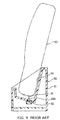
- JP'503 discloses a mobile device that is mounted obliquely on the stationary device.
- a mobile device or phone 60 is mounted on a stationary device or battery charger 50 for charging.
- the battery charger 50 comprises a housing 51 that has an inclined support recess 52 into which the mobile phone 60 is placed.
- a connector 53 is provided on the bottom of the support recess 52 and has a pin terminal 53A that is movable in an up-and-down direction.
- a flat terminal 61 is provided on the bottom of the mobile phone 60 so that when the mobile phone 60 is mounted in the support recess 52, the terminals 53A and 61 are brought into contact with each other for electrical connection. The contact point between the terminals 53A and 61 moves around during the electrical connection, producing the so-called "wiping effect".
- both the devices are connected in a fixed posture so that no wiping effect is obtained.
- a stationary device 10 comprises a case 11 that has an upper opening in which a connector 12 provided and a receiving section 13 that extends obliquely from the side of the upper opening and has an engaging projection 13A.
- the connector 12 comprises a housing 14 of an insulative material and a plurality of terminals 15 and 16 arranged in the housing 14.
- the housing 14 has a horizontal face 14A and an inclined face 14B that extends obliquely downwardly from the horizontal face 14A.
- a pair of mount guiding columns 17 extend obliquely upwardly from the edge between the horizontal and inclined faces 14A and 14B and flank the contact sections 15A and 16A of the terminals 15 and 16.
- a pair of leg sections 18 extend laterally from opposite sides of the housing 14 and have fixing apertures 18A into which screws are inserted to secure the connector 12 to the stationary device 10.
- a terminal support 19 extend upwardly to a half of the height of the mount guiding columns 17 and has a plurality of support slots 19A that support the terminals 15 and 16 and communicate with respective internal spaces 20 of the housing 14.
- the slots 19A and. the internal spaces 20 extend in respective planes parallel to the picture plane of Fig. 2.
- the contact section 16A of a power terminal 16 extends upwardly from the terminal support 19 more than Lhe contact section 15A of a signal terminal 15.
- the power terminals 16 on opposite ends of the terminal row and the signal terminals 15 between them are used to transmit power terminals and signal terminals, respectively. Both the terminals 15 and 16 are identical except for the height of the contact sections 15A and 16A and, therefore, only the power terminal 16 will be described.
- the power terminal 16 has, from above, a contact section 16A, a flexible section 16B, a fixing section 16C, and a connection section 16D.
- the contact section 16A has an inverted U-shape that projects from the support slot 19A.
- the flexible section 16B extends obliquely downwardly from the contact section 16A and then obliquely upwardly to form a U-shaped curve in the internal space 20 so that it is flexed when the contact section 16A is pressed downwardly.
- the fixing section 16C is brought into close contact with and supported by the inner face of the housing 14.
- the connection section 16D extends horizontally through the housing 14 and is connected to a corresponding trace of a circuit board provided in the stationary device 10.
- the mount guiding column 17 has a circular top face 17A and a pair of inclined side faces 17B. Best shown in Fig. 2, the contact sections 15A and 16A are located within the outline of the guiding columns 17.
- a rotation guiding column 21 is provided adjacent to one of the mount, guiding columns 17.
- the rotation guiding column 21 is lower than the mount guiding columns 17 and has a circular top or rotation guiding face 21A.
- the mobile device 30, such as mobile telephone comprises a case 31 and a connector 32 provided on the bottom of the case 31, in which a circuit member (not shown) is accommodated.
- An engaging recess 31A is provided in a side of the case 31 for engagement with the engaging projection 13A to support the mobile device 30 in an obligue posture (Fig. 5).
- the connector 32 comprises a housing block 33 of an insulative material, a plurality of terminals 34 provided in the housing block 33, and a shield tube 35 provided around the terminals 34.
- a receiving cavity 36 is provided in the housing 33 for accommodating the mount guiding columns 17 of the mating connector 12.
- a terminal island 37 is provided in the receiving cavity 36.
- a pair of mount recesses 38 are provided in the receiving cavity 36 on opposite sides of the terminal island 37.
- a plurality of indentations 39 are provided in the terminal island 37 at positions corresponding to the terminals 15 and 16 of the stationary device 10 for accommodating the contact sections 34A of terminals 34.
- the contact section 34A is provided at one end of the terminal 34 and has a flat section on the bottom of the indentation 39.
- the contact, sections 34A of a plurality of terminals 34 are at the same level so that the power terminals 16 of the stationary device 10 make contact with the terminals 34 of the mobile device 30 prior to the signal terminals 15.
- the terminal 34 has at the other end a connection section 34B that is connected to a corresponding circuit (not shown) of the mobile device 30.
- the shield plate or tube 35 extend along the inside wall of the receiving cavity 36 such that the open edge 35A is located at the open edge of the receiving cavity 36.
- a bearing recess 40 is provided in the housing 33 outside the shield tube 35 for accommodating the rotation guiding column 21 of the stationary device 10. It has at the bottom a circular hearing face 40A that matches the rotation guiding face 21A of the guiding column 21 for sliding movement along with rotation of the mobile device 30 to the inclined position.
- the mount guiding columns 17 and the mount recesses 38 are not in contact; i.e., there is a gap between them.
- a rotation guiding section 19B is provided on the terminal support 19. More specifically, the terminal support 19 has circular top faces between adjacent contact sections 15A and 16A.
- a circular bearing face 33A is provided on the housing 33 of the connector 32 at a position corresponding to the rotation guiding face 19B.
- FIG. 7 a modification to the embodiment of Fig. 6 is shown.
- the circular bearing face 33A of Fig. 6 is replaced by a V-shaped bearing face 33B.
- the rotation guiding face may be provided on the mount guiding column by making its top a concave or convex face while the bearing face of a mobile device is made to match the configuration.
- the outline of the mount guiding column may be made of a continuously curved line or a plurality of broken lines joined together. At any rate, it is desired that the mounting and rotation of the mobile device on the stationary device be made smooth and the mounting posture be stable.
- the housing of a connector for each of the devices, especially stationary device may be integrated with the device case.
- the receiving section may be integrated with a side wall of the mount guiding column, which is made tall for stabilizing the stationary device.
- the mount guiding column may stand upright.
- the mount guiding column enables not only guide but also rotate the mobile device along the rotation guiding face so that it is possible to not only provide easy and accurate positioning by the mount guiding column but also smooth rotation by the rotation guiding face to provide the wiping effect, resulting in the clean contact sections of terminals.
Landscapes
- Details Of Connecting Devices For Male And Female Coupling (AREA)
- Telephone Set Structure (AREA)
- Coupling Device And Connection With Printed Circuit (AREA)
Abstract
Description
Claims (12)
- A stationary device for receiving a mobile device therein for electrical connection, said stationary device comprising:a stationary case;a stationary connector supported by said stationary case, said stationary connector including:a connector housing having a terminal support;a plurality of terminals having contact sections projecting from said terminal support;a pair of mount guiding columns provided on said connector housing and has such a shape and size as to allow said mobile device to rotate to an inclined position;a receiving member extending from said stationary case for supporting said mobile device at said inclined position; androtation guiding means for guiding said mobile device for rotation to said inclined position.
- The stationary device according to claim 1, wherein said connector housing is integrated with said stationary case as a unit.
- The stationary device according to claim 1, wherein said mount guiding columns are provided on opposite sides of said terminal support.
- The stationary device according to claim 1, wherein said mount guiding columns are provided on opposite sides of said terminal support: in a direction that said terminals are arranged.
- The stationary device according to claim 1, wherein said rotation guiding means has a circular top face.
- The stationary device according to claim 5, wherein said circular top face is either convex or concave.
- The stationary device according to claim 1, wherein said mount guiding columns are inclined toward said inclined position.
- A stationary connector for a stationary device that receives a mobile device therein for electrical connection, said stationary connector comprising:a connector housing having a terminal support;a plurality of terminals having a contact section projecting from said terminal support;a pair of mount guiding columns provided on opposite sides of said terminal support and having such a shape and size as to allow said mobile device to rotate to an inclined position; androtation guiding means provided on said connector housing for guiding said mobile device to said inclined position.
- The mobile device according to claim 1, which further comprises a bearing face for engagement with said rotation guiding means of said stationary device.
- The mobile device according to claim 9, wherein said bearing face has a curved face that matches a curved face of said rotation guiding means.
- The mobile device according to claim 9, wherein said bearing face has a V-shaped section.
- A mobile connector for said mobile device for connection with said stationary connector according to claim 8, said mobile connector has a bearing recess with a bearing face for engagement with said rotation guiding means.
Applications Claiming Priority (2)
| Application Number | Priority Date | Filing Date | Title |
|---|---|---|---|
| JP2000129354A JP2001313137A (en) | 2000-04-28 | 2000-04-28 | Portable devices, stationary devices therefor and electrical connectors for these devices |
| JP2000129354 | 2000-04-28 |
Publications (2)
| Publication Number | Publication Date |
|---|---|
| EP1150385A2 true EP1150385A2 (en) | 2001-10-31 |
| EP1150385A3 EP1150385A3 (en) | 2001-11-14 |
Family
ID=18638645
Family Applications (1)
| Application Number | Title | Priority Date | Filing Date |
|---|---|---|---|
| EP01110495A Withdrawn EP1150385A3 (en) | 2000-04-28 | 2001-04-27 | Mobile device, stationary device, and electrical connector for them |
Country Status (2)
| Country | Link |
|---|---|
| EP (1) | EP1150385A3 (en) |
| JP (1) | JP2001313137A (en) |
Cited By (4)
| Publication number | Priority date | Publication date | Assignee | Title |
|---|---|---|---|---|
| ES2320611A1 (en) * | 2006-11-06 | 2009-05-25 | Inoitulos, S.L. | "ADAPTER DEVICE FOR CHARGING PORTABLE ELECTRONIC DEVICES". |
| EP2239821A2 (en) * | 2009-04-09 | 2010-10-13 | Peiker acustic GmbH & Co. KG | Adapter for a micro-USB socket or a mini-USB socket and assembly with mobile device, holder and adapter |
| CN106505344A (en) * | 2015-09-04 | 2017-03-15 | 苹果公司 | Electronic device with contacts flush with housing |
| CN118610849A (en) * | 2024-08-08 | 2024-09-06 | 深圳鸿磊五金制品有限公司 | Terminal bending device and bending processing method thereof |
Families Citing this family (4)
| Publication number | Priority date | Publication date | Assignee | Title |
|---|---|---|---|---|
| US9948018B2 (en) | 2015-09-08 | 2018-04-17 | Apple Inc. | Low-profile power and data contacts |
| US10707627B2 (en) | 2017-09-29 | 2020-07-07 | Apple Inc. | Hybrid connector |
| JP7473794B2 (en) | 2020-04-01 | 2024-04-24 | 株式会社デンソーウェーブ | Cradle |
| JP7488777B2 (en) * | 2021-01-27 | 2024-05-22 | 株式会社ヨコオ | Terminal connection structure, vehicle-mounted antenna device, and method for assembling terminal connection structure |
Family Cites Families (2)
| Publication number | Priority date | Publication date | Assignee | Title |
|---|---|---|---|---|
| US4778403A (en) * | 1987-07-15 | 1988-10-18 | Elco Corporation | Zero insertion force connector |
| FR2688350B1 (en) * | 1992-03-09 | 1995-09-29 | Marechal Exploit Procedes | ELECTRICAL CONNECTION DEVICE AND MORE PARTICULARLY CHARGE CONNECTOR. |
-
2000
- 2000-04-28 JP JP2000129354A patent/JP2001313137A/en active Pending
-
2001
- 2001-04-27 EP EP01110495A patent/EP1150385A3/en not_active Withdrawn
Cited By (6)
| Publication number | Priority date | Publication date | Assignee | Title |
|---|---|---|---|---|
| ES2320611A1 (en) * | 2006-11-06 | 2009-05-25 | Inoitulos, S.L. | "ADAPTER DEVICE FOR CHARGING PORTABLE ELECTRONIC DEVICES". |
| ES2320611B1 (en) * | 2006-11-06 | 2010-01-12 | Inoitulos, S.L. | "ADAPTER DEVICE FOR CHARGING PORTABLE ELECTRONIC DEVICES". |
| EP2239821A2 (en) * | 2009-04-09 | 2010-10-13 | Peiker acustic GmbH & Co. KG | Adapter for a micro-USB socket or a mini-USB socket and assembly with mobile device, holder and adapter |
| CN106505344A (en) * | 2015-09-04 | 2017-03-15 | 苹果公司 | Electronic device with contacts flush with housing |
| US10579097B2 (en) | 2015-09-04 | 2020-03-03 | Apple Inc. | Electronic device with contacts flush with housing |
| CN118610849A (en) * | 2024-08-08 | 2024-09-06 | 深圳鸿磊五金制品有限公司 | Terminal bending device and bending processing method thereof |
Also Published As
| Publication number | Publication date |
|---|---|
| JP2001313137A (en) | 2001-11-09 |
| EP1150385A3 (en) | 2001-11-14 |
Similar Documents
| Publication | Publication Date | Title |
|---|---|---|
| US6902411B2 (en) | Connector assembly | |
| US7140896B2 (en) | Connector | |
| CN100448109C (en) | Connector | |
| US7083454B2 (en) | Connector | |
| KR100330863B1 (en) | Coaxial Connector | |
| US7534140B2 (en) | Electrical connector with improved metal spring | |
| US7621768B2 (en) | Space saving miniature connector for electric devices | |
| KR101465826B1 (en) | Electrical connector module | |
| US20010036763A1 (en) | Mobile device, stationary device, and electrical connectors for them | |
| US10601179B2 (en) | Connector | |
| KR20090051259A (en) | Camera socket module | |
| WO2010003100A1 (en) | Board-to-board connector | |
| JP2021153070A (en) | Manufacturing method of electric connector for circuit board | |
| JPH04229965A (en) | Connector for circuit board with latch device | |
| US5883787A (en) | Floating guided connector and method | |
| US6450824B1 (en) | Connector including movable cover | |
| JP2000182696A (en) | Structure of power source connector | |
| US7040907B2 (en) | Electric plug | |
| CN101409410B (en) | Connector | |
| JP6849555B2 (en) | Electrical connector assembly | |
| JP2001313137A (en) | Portable devices, stationary devices therefor and electrical connectors for these devices | |
| US20060281353A1 (en) | Connector | |
| US7077674B2 (en) | Board attachment type electrical connector | |
| US20080045070A1 (en) | Electrical connector with improved locking arms | |
| JP2001126815A (en) | connector |
Legal Events
| Date | Code | Title | Description |
|---|---|---|---|
| PUAI | Public reference made under article 153(3) epc to a published international application that has entered the european phase |
Free format text: ORIGINAL CODE: 0009012 |
|
| PUAL | Search report despatched |
Free format text: ORIGINAL CODE: 0009013 |
|
| AK | Designated contracting states |
Kind code of ref document: A2 Designated state(s): AT BE CH CY DE DK ES FI FR GB GR IE IT LI LU MC NL PT SE TR |
|
| AX | Request for extension of the european patent |
Free format text: AL;LT;LV;MK;RO;SI |
|
| AK | Designated contracting states |
Kind code of ref document: A3 Designated state(s): AT BE CH CY DE DK ES FI FR GB GR IE IT LI LU MC NL PT SE TR |
|
| AX | Request for extension of the european patent |
Free format text: AL;LT;LV;MK;RO;SI |
|
| RIC1 | Information provided on ipc code assigned before grant |
Free format text: 7H 01R 13/22 A, 7H 01R 13/629 B, 7H 01R 13/631 B |
|
| AKX | Designation fees paid | ||
| REG | Reference to a national code |
Ref country code: DE Ref legal event code: 8566 |
|
| STAA | Information on the status of an ep patent application or granted ep patent |
Free format text: STATUS: THE APPLICATION IS DEEMED TO BE WITHDRAWN |
|
| 18D | Application deemed to be withdrawn |
Effective date: 20020515 |