BACKGROUND OF THE INVENTION
1. Field of the Invention
The present invention relates to an optical pickup
servo-control apparatus for use with an optical disc player.
2. Description of the Related Art
Servo control is usually used to control an optical pickup
for reading recorded information at a desired reading position
for the purpose of achieving good reproduction performance in a
player for optical discs, such as compact discs (CD) and digital
versatile discs (DVD). An optical disc, however, usually
contains defects, such as various kinds of flaws and contamination
which occur during, for example, the manufacturing process or the
use of the disc. Such defects impede a stable operation of the
above-mentioned servo control.
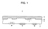
Fig. 1 is a sectional view of an optical disc 1, showing
the kinds of major defects which may occur. The optical disc 1
includes a protection layer 3, a reflective layer 4 which reflects
the light beam emitted from the optical pickup, and a transparent
cover layer 5 made of a transparent material such as a plastic
and the like.
Referring to Fig. 1, a defect I is a flaw called an
"interruption" in the reflective layer 4, caused in the
manufacturing process of the disc. A defect II is a dirt called
a "black dot" on the disc's surface or the transparent cover layer
5. A defect III is a "fingerprint" of human fat on the disc surface
7. A defect IV is a flaw called a "scratch" on the disc surface
7.
The existence of such defects on a disc causes "dropout"
in read signal (RF signal) generated in the optical pickup when
the disc is played, and deteriorates the controllability of servo
control including tracking control, focusing control, tilt
control and the like. A conventional method, for example, for
preventing the adverse influence on servo control caused by such
defect is to continue servo control by holding the control value
of servo control, or the tracking error value, focus error value,
or the like to the value before the defect was detected
(hereinafter, simply referred to as "pre-value hold").
The servo control, however, becomes unstable when the
dropout continues for a relatively long time or the dropout is
of a burst type, because a bias or deviation value indicated by
a value in the pre-value-hold method (hereinafter, simply
referred to as a "hold value") drifts too far from the actual bias
value. For example, the drive signal for the optical pickup
drastically fluctuates during the period when a dropout occurs,
causing servo control instability as shown in Fig. 2. In addition,
as the transient phenomenon arises after termination of the
dropout, servo control becomes unstable because the focus error
signal is delayed in converging into a normal value, for example,
as shown in Fig. 3. Therefore, the performance of servo control
may be deteriorated or a gross deterioration in reproduction
quality may be caused.
The defect such as a fingerprint or a black dot is usually
formed over a plurality of tracks in the radial direction of the
disc (i.e., in a certain range of a rotational angle of the disc).
Servo control also needs to be stabilized effectively against such
defects.
OBJECT AND SUMMARY OF THE INVENTION
Therefore, it is an object of the present invention to
provide a servo control apparatus which is capable of performing
stable high-precision servo control during the period of time when
a dropout occurs and after the termination of the dropout even
if the dropout continues for a long time or the dropout is of a
burst type.
It is another object of the present invention to provide
a servo control apparatus which has a high capability of dealing
with various kinds of defects and of performing stable high-precision
servo control.
To achieve the object, according to the present invention,
there is provided a servo control apparatus of an optical pickup
for reading recorded information from a recording medium to
generate a read signal, which comprises error signal extracting
means for extracting an error signal from the read signal, the
error signal indicating a deviation from a servo target value of
the optical pickup; equalizing means including a phase
compensator for equalizing the error signal by the phase
compensator to generate a drive signal; driving means for changing
the servo position of the optical pickup in response to the drive
signal; dropout detecting means for extracting an envelope signal
from the read signal to detect a dropout of the read signal; and
controlling means for changing an equalization characteristics
of the equalizing means in accordance with an amplitude of the
envelope signal during the period of time when the dropout occurs.
According to the present invention, there is provided a
servo control apparatus of an optical pickup for reading recorded
information from a recording medium to generate a read signal,
which comprises error signal extracting means for extracting an
error signal from the read signal, the error signal indicating
a deviation from a servo target value of the optical pickup;
equalizing means including a phase compensator for equalizing the
error signal by the phase compensator to generate a drive signal;
driving means for changing the servo position of the optical
pickup in response to the drive signal; dropout detecting means
for extracting an envelope signal from the read signal to detect
a dropout of the read signal; and controlling means for changing
an equalization characteristics of the equalizing means in
response to an occurrence of the dropout.
BRIEF DESCRIPTION OF THE DRAWINGS
Fig. 1 is a sectional view of an optical disc schematically
showing the kinds of major defects caused on an optical disc.
Fig. 2 shows changes of the drive signal supplied to the
optical pickup during a dropout period.
Fig. 3 shows changes of the focus error signal due to the
transient phenomenon after a dropout period.
Fig. 4 is a schematic block diagram of the configuration
of a servo control apparatus for an optical disc player according
to the present invention.
Fig. 5 is a schematic block diagram of the configuration
of an equalizer according to a first embodiment of the present
invention.
Fig. 6 is a schematic block diagram of the configuration
for generating an envelope signal and a dropout detection signal.
Figs. 7A-7C are illustrating waveforms when an envelope
signal is extracted from an RF read signal and a dropout detection
signal is generated from the envelope signal.
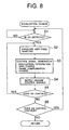
Fig. 8 is a flowchart of the procedure for changing the
differentiation/integration gain characteristics and the phase
compensation characteristics of the equalizer in accordance with
the envelope level.
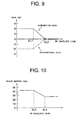
Fig. 9 is a graph of gain values against the envelope level
when the equalizer differentiation/integration gain is changed.
Fig. 10 is a graph of the envelope level phase margin when
the equalizer phase compensation characteristics are changed.
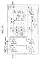
Fig. 11 is a schematic block diagram of the configuration
of the equalizer in a servo control apparatus according to a second
embodiment of the present invention.
Fig. 12 is a diagram of an example in which an error change
generation process is realized with individual circuit blocks.
Fig. 13 is a graph of changes in proportional gain and
integration gain against an error change.
Fig. 14 is a schematic block diagram of the configuration
of the equalizer according to a modification of the second
embodiment of the present invention.
Fig. 15 is a block diagram of an example of the configuration
of a servo control apparatus according to a third embodiment of
the present invention.
Fig. 16 is a block diagram of the major parts of a servo
control apparatus, which is realized with circuit blocks,
according to a fourth embodiment of the present invention.
Fig. 17 is a block diagram of the major parts of a servo
control apparatus according to a modification of the fourth
embodiment of the present invention.
Fig. 18 a flowchart of the focus-error-hold procedure to
be performed by a controller in a fifth embodiment of the present
invention.
Fig. 19 is a flowchart of the equalizer equalization
characteristics change procedure in the fifth embodiment of the
present invention.
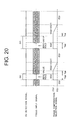
Fig. 20 is a time chart for illustrating an equalizer
equalization change in the fifth embodiment of the present
invention.
DETAILED DESCRIPTION OF THE PREFERRED EMBODIMENT
The embodiments of the present invention will be described
in more detail with reference to the accompanying drawings. The
same reference numerals refer to substantially similar elements
throughout the drawings.
First Embodiment
Fig. 4 is a block diagram of the configuration of a servo
control apparatus 10 of an optical disc player according to the
present invention.
In Fig. 4, the optical disc 1 is rotated by a spindle motor
8. The spindle motor 8 is provided with an FG signal generator
(not shown) for generating one pulse for each predetermined angle
of spindle rotation. A generated FG pulse signal is supplied to
a controller 23.
An optical pickup 11 emits a laser light beam on the optical
disc 1, receives the light beam reflected from the optical disc
1, and generates a signal in response to the amount of the received
light. An optical detector 12 provided in the optical pickup 11
is, for example, a 4-partitioned optical detector consisting of
four light-receiving elements. Each of the four light-receiving
elements receives the light reflected from a beam spot (not shown),
converts it into an electric signal to output as read signals RB1-RB4,
respectively. The optical pickup 11 is further provided with
a driver 19 comprising a tracking actuator for making the
direction of an objective lens (not shown) or the reading point
thereof, biased in the radial direction, and a focusing actuator
for adjusting the focusing point of the beam spot.
With the above-mentioned configuration, the optical pickup
11 reads recorded information from the optical disc 1, and
supplies the read signals RB1- RB4 to a signal processing circuit
15.
An RF amplifier is provided in the signal processing circuit
15. The RF amplifier amplifies the read signals RB1- RB4, and
extracts a tracking error signal TE and a focus error signal FE
based on the amplified read signals. More specifically, the
signal processing circuit 15 generates the focus error signal FE
using the read signals RB1- RB4. The focus error signal FE is a
differential signal between two added signals obtained by adding
read signals from the light-receiving elements diagonally
opposing each other. The signal processing circuit 15 also
generates a tracking error signal TE by the phase difference
method using the read signals RB1- RB4, for example. The tracking
error signal TE and the focus error signal FE generated in the
signal processing circuit 15 are supplied to a servo-equalizer
(hereinafter, simply referred to as an equalizer) 17.
As described in detail below, the equalizer 17 is a circuit
for compensating the amplitude and phase of error signals, such
as the tracking error signal TE and the focus error signal FE
generated in the signal processing circuit 15. More particularly,
the equalizer 17 performs equalization processing on error
signals so as to have frequency characteristics suitable for servo
control, and supplies the equalized signals to the driver 19 for
the optical pickup 11 as drive signals TD and FD, respectively.
The driver 19 generates actuator operating signals TDRV, FDRV
based on the supplied drive signals TD and FD. The servo control
is performed by operating the actuator in the optical pickup 11.
Furthermore, according to the present invention, there is
provided a dropout detector 21 for receiving an RF read signal
from the signal processing circuit 15 and for detecting defects
formed on the optical disc 1, i.e. , dropouts in the RF read signal;
and a controller 23 for controlling the equalizer 17 in accordance
with the dropout detection signal detected by the dropout detector
21, the above-mentioned FG pulse signal, and signals from the
signal processing circuit 15. The controller 23 is provided with
a timer, a memory for storing various data, such as the servo
controlled value, the tracking error value, or the focus error
value, and an operation section for calculating the coefficient
of the equalizer 17 and the like as described below. The
controller 23 is configured with, for example, a microcomputer
or a plurality of circuit blocks.
In the servo control apparatus 10, a control range is
determined in accordance with the transfer function of the
actuator and/or the detection sensitivity of the error detectors
including the optical system such that the servo does not get out
of place even though a disturbance in the servo system such as
wobbling rotation of the disc occurs. Gain characteristics and
phase characteristics are set so that the system operates with
stability within the range. In particular, equalization
characteristics are determined so as to secure a sufficient phase
margin in the required range of the servo system. More
specifically, equalization is performed so as to obtain a
sufficient phase margin in the frequency range where the gain
characteristics of an open-loop transfer function become 0dB.
Equalization for focus servo, for example, is performed so as to
obtain a sufficient phase margin within the frequency range of
several hundred hertz to several kilohertz.
Fig. 5 shows the configuration of the equalizer 17 in the
embodiment. The tracking error signal TE and the focus error
signal FE extracted in the signal processing circuit 15 are
supplied to a proportion/differentiation gain multiplier (APD)
31 to be multiplied by a coefficient bearing a predetermined gain.
The multiplied error signals are supplied to a
proportion/differentiation compensator 32 so as to undergo phase
compensation.
The proportion/differentiation compensator 32 is composed
of a filter which can shift the phase of an input signal. More
specifically, for example, a digital filter of the secondary IIR
(infinite impulse response filter) and secondary FIR (finite
impulse response filter) type can be used as shown in Fig. 5. The
digital filter comprises coefficient multipliers 33A-33E, delay
elements 34A-34D, and adders 35A-35B. The phase compensation
characteristics can be changed by altering each of the
coefficients A0-A4 of the coefficient multipliers 33A-33E.
The error signal from the signal processing circuit 15 is
also supplied to an integration gain multiplier (AI) 37. The
integration gain multiplier (AI) 37 multiplies the supplied error
signal by a set gain, and supplies it to an integrator 38. The
integrator 38 is so called a low-pass filter (LPF) including a
primary IIR filter. In other words, the integrator 38 is an
accumulating circuit for the low-pass components of error signals,
and serves as a holding circuit for holding past low-frequency
component of the error signals. An output signal from the
integrator 38 is added to an output signal from the above-mentioned
proportion/differentiation compensator 32 at an adder
43, and the signal obtained from the adder is supplied to the driver
19 of the optical pickup 11 as drive signals (TD, FD).
Thus, when the integration gain of the integration gain
multiplier (AI) 37 increases, the output signal from the
integrator 38 increases in magnitude, and the component, which
is proportional to the current error, decreases in magnitude
relatively. As a result, the tracking performance to current
disturbances (for example, an unexpected disturbance such as
dropout of an RF signal due to a defect) deteriorates, making it
possible to avoid the influence of the disturbance temporarily.
If this operation is continued, however, the focused state becomes
impossible to be maintained due to a deterioration of the tracking
performance to disturbances (for example, due to wobbling
rotation of the disc) which should essentially be tracked. Thus,
the integration gain and the proportional gain should be
determined in respect to the above-mentioned tracking performance
to current disturbances.
As is shown in Fig. 5, the gains of the
proportion/differentiation gain multiplier (APD) 31 and the
integration gain multiplier (AI) 37 can be changed by a control
signal from the controller 23. Similarly, the phase
characteristics of the proportion/differentiation compensator
32 can be changed by altering a coefficient of the coefficient
multiplier (in the case shown in Fig. 5, coefficient A2, a
secondary coefficient, of the coefficient multiplier 33C) by
using a control signal from the controller 23. In the embodiment,
the controller 23 generates control signals for the
proportion/differentiation gain multiplier (APD) 31, the
integration gain multiplier (AI) 37, and the
proportion/differentiation compensator 32 based on the amplitude
of the envelope signal of the RF read signal.
The generation of the envelope signal and the dropout
detection signal will be described below with reference to Figs.
6, and 7A-7C. As is shown in Fig. 6, the envelope signal (Fig.
7B) is extracted from an RF read signal (Fig. 7A) by an envelope
detector circuit in the signal processing circuit 15, and supplied
to the controller 23. The envelope signal is compared with a
predetermined discrimination level in a comparator circuit in the
dropout detector 21, and a dropout detection signal (Fig. 7C)
having a predetermined voltage level (Vd) is generated. In the
signal processing circuit 15, the generated envelope signal may
be supplied to the controller 23 through a suitable low-pass
filter (LPF).
The operation performed by the controller 23 for
controlling gains and phases will be described with reference to
the flowchart in Fig. 8 and to Figs. 9 and 10. It is determined
whether or not any dropout is detected in the controller 23(step
S1). For example, it is determined whether or not a dropout has
started by a rise (or fall) in the envelope signal. The amplitude
of the envelope signal is then sampled in response to the dropout
detection signal (step S2).
As is shown in Fig. 9, the controller 23 generates a control
signal for changing the gains of the proportional differentiation
gain multiplier (APD) 31 and the integration gain multiplier (AI)
37 in accordance with the sampled amplitude. More particularly,
when the envelope amplitude value (hereinafter referred to as
"envelope level") is below a predetermined value (EL1), a control
signal is generated so as to decrease the proportional gain (-6dB)
and increase the integration gain (+6dB) because the reliability
of the error signal is low. On the other hand, when the envelope
level exceeds another predetermined value EL2 (≥ EL1), the
proportional and integration gains are not changed. In other
words, a control signal indicating the change value of 0dB is
generated. When the envelope level is between EL1 and EL2,
control is performed so as to change the change value of the
proportional gain from -6dB to 0dB as the envelope level increases,
and at the same time gradually change the integration gain from
+6dB to 0dB.
As described above, the controller 23 further generates a
control signal for changing the secondary coefficient (A2) of the
proportion/differentiation compensator 32 in accordance with the
envelope level. More particularly, a control signal is generated
for changing the value of the coefficient so as to control
transient phenomenon by increasing phase margin when the envelope
level is below a first predetermined value (EL3), as is shown in
Fig. 10. On the other hand, a control signal is generated to
indicate that the phase is not to be changed when the envelope
level exceeds a second predetermined value EL4 (≥ EL3). In this
manner, a control signal is supplied to the equalizer 17 so as
to change the gain and phase in accordance with the envelope level
(step S4).
It is then determined whether or not the dropout is
continuing (step S5). When the dropout is continuing, the
procedure goes back to step S2 to sample the envelope amplitude,
and to repeat the steps described above. When the dropout is
terminated (i.e., when the dropout is disappeared), whether or
not the control for changing the gain and phase is to be continued
is determined (step S6). The procedure goes back to step S1 to
repeat the above steps when the changing control is to be continued.
Control exits the process routine when the changing control is
not to be continued. Thus, the gain and phase of the equalizer
17 are controlled in accordance with an amplitude of the envelope
signal during the period of time when dropout occurs as described
above.
Although the embodiment has been described taking an
example where both the proportional gain and integration gain are
changed simultaneously, only one gain can be changed. In that
case, all that needs to be done is to change the integration gain
relative to the proportional gain. The above-described change
value of gains and phase margin is a mere example. It may be set
to a suitable value in accordance with the servo system to be used.
As described above, stable high-precision servo control is
realized by changing the gain characteristics and phase
characteristics of the equalizer 17 in accordance with the
amplitude of the envelope signal during the period when dropout
occurs.
Second Embodiment
Fig. 11 is a schematic diagram of the configuration of an
equalizer in the servo control apparatus 10 according to a second
embodiment of the present invention. The difference between the
embodiment and the first embodiment is that, as is shown in Fig.
11, the equalizer 17 is further provided with a
proportion/differentiation gain multiplier (APD2) 51 and a second
integration gain multiplier (AI2) 53 so that the gains of the
multipliers can be changed by a second control signal from the
controller 23.
The controller 23 controls the equalization
characteristics of the equalizer 17 using a second control signal
for changing the integration gain of the second integration gain
multiplier (AI2) 53 or the proportional gain of the second
proportional differentiation gain multiplier (APD2) 51 in
accordance with the change of an error signal in addition to the
control signal for changing gains in accordance with the envelope
level as described in the first embodiment.
In this embodiment, a change amount or variance of an error
signal (hereinafter, simply referred to as "error change")
defined below is used in order to complement gain control by the
envelope level.
Error change = integral value of error (over an angular
section of rotation where a dropout occurs) - integral value of
error (over the same angular section of rotation before the
dropout occurs).
In more detail, an integrated or integral value is obtained
for an error signal over a range or section of rotational angle
(hereinafter, refereed to as an angular section of rotation) on
a track before a dropout occurs. An integral value is, then,
obtained over the same angular section of rotation on a track where
a dropout occurs. The error change is obtained by subtracting
the integral value for the angular section of rotation where a
dropout occurs from the integral value before the occurrence of
the dropout for the same angular section of rotation.
More specifically, for example, the difference between an
integral value of the error signal in one period of the FG signal
when dropout occurred and an integral value of the error signal
in the same FG signal period, i.e., in the same angular section
on a different track as that of the former can be used. A drive
signal may be used instead of the error signal.
The error change can be generated in the controller 23 as
described above. The generation process of the error change can
be performed in circuit blocks shown in Fig. 12. After an error
signal is converted to a digital signal in an analog/digital (A/D)
converter 56, an integral value is generated by an integration
circuit 57. The integral value is supplied to an input terminal
on the L terminal of a selector 60 and to a subtracter 59. An
output terminal of the selector 60 is connected to an FIFO
(first-in first-out) memory 58. The output from the FIFO memory
58 is supplied to an input H terminal of the selector 60. A dropout
detection signal is supplied to a control terminal of the selector
60. With such configuration, the selector 60 supplies the
integral value supplied from the integration circuit 57
selectively to the FIFO memory 58 when the dropout detection
signal is on the L level, i.e. , when dropout is not detected. Or,
the selector 60 supplies an output signal from the FIFO memory
58 selectively to the FIFO memory 58 when the dropout detection
signal is on the H level, i.e., when a dropout is detected.
The FIFO memory 58 consists of N stages of memories. An
FG pulse signal having N pulses/rotation of the disc is supplied
to the FIFO memory 58 through the gate circuit 60. The content
of the memory 58 is sequentially supplied to the subtracter 59
in response to the FG pulse signal. In other words, the output
from the subtracter 59 is an integral value of the error signal
in the current angular section of rotation minus an integral value
of the error signal in the same angular section of rotation on
a different track. The above configuration is designed so that
the supply of an integral value of the error signal to the FIFO
memory 58 is forbidden and data in the FIFO memory 58 is not updated
when a dropout is detected. Consequently, the latest integral
value before a dropout is detected is stored in the FIFO memory
58.
The procedure of control operation performed by the
controller 23 is similar to that in the first embodiment except
that, in addition to the first control signal for changing gains
in accordance with the envelope level, a second control signal
for changing gains in accordance with the error change is supplied
to the second proportion/differentiation gain multiplier (APD2)
51 and the second integration gain multiplier (AI2) 53 in the
equalizer 17. More particularly, as is shown in Fig. 13, the
controller 23 decreases the change of the proportional gain as
the error change decreases when the error change is below a first
predetermined value (EV1) in the negative region (in the case
shown in Fig. 13, from 0dB to -0.2dB). The controller 23 increases
the change of integration gain (from 0dB to 0.4dB) as well as
decreases the proportional gain, thus increases the integration
gain. Specifically, it is assumed that a normal error signal
cannot be obtained due to the dropout (i.e., the error signal is
assumed to be nearly 0). Therefore, control is maintained so as
not to track the error signal affected by the dropout by increasing
the integration gain as well as by decreasing the proportional
gain. On the other hand, the change of proportional gain is
increased (from 0dB to 0.4dB) as the error change increases when
the error change exceeds a second predetermined value (EV2) in
the positive region. More specifically, the change of
integration gain is decreased (i.e., from 0dB to -0.4dB) at the
same time as the proportional gain is increased, thus the
integration gain is decreased. In other words, control is
considered to be greatly deviated from the target state due to
disturbances caused by the rotation of the disc and the like when
an error change exceeds the second predetermined value (EV2) in
the positive region. Thus, the integration gain is decreased so
as to improve the tracking performance of the servo control
apparatus to the disturbances at the same time as the proportional
gain is increased. No compensation of the proportional gain and
the integration gain is performed (i.e., 0dB) when the error
change is between the first predetermined value (EV1) and the
second predetermined value (EV2). The change of the above gains
can be suitably selected in accordance with the servo system or
the kind of the disc to be used.
As described above, more stable high-precision servo
control can be achieved by adding gain compensation to gain
control by the envelope level. Although a description has been
made of an example where the gains of the second
proportion/differentiation gain multiplier (APD2) and the second
integration gain multiplier (AI2) are adjusted so as to compensate
the gain of the equalizer 17, the present invention is not limited
to the case but applicable to various cases. For example, the
control signal may be determined based on the above error change
for changing the characteristics of the
proportion/differentiation gain multiplier (APD) 31, the
integration gain multiplier (AI) 37, and the
proportion/differentiation compensator 32 in the equalizer 17
in Fig. 5, which is used for illustrating the first embodiment.
Another possible design is, as shown in Fig. 14, to change the
proportional gain or the phase characteristics of an equalizer
having no integration gain multiplier (AI) 37.
As mentioned above, the characteristics of the equalizer
17 are adjusted by comparing the error change at the position on
the track (i.e., angular section of rotation) where a dropout
occurred with that in the same angular section on the track before
the dropout occurred. Accordingly, servo control can be
stabilized while a dropout is occurring even though there is a
defect at a certain region over a plurality of tracks to cause
the dropout of an RF signal. In addition, the transient
phenomenon after the disappearance of the dropout can be
controlled to realize stable high-precision servo control.
Third Embodiment
Fig. 15 is a block diagram illustrating the configuration
of a servo control apparatus 10 according to a third embodiment
of the present invention. In order to simplify the description,
the major part of the configuration of the servo control apparatus
10 is shown in circuit blocks.
In the embodiment, a focus error signal from a focus error
detector 61 is supplied to the equalizer 17 through a switch 62,
and at the same time, the error value indicated by the focus error
signal is supplied to and held in an error value holder 63. The
switch 62 selectively supplies a focus error signal from the focus
error detector 61 or the error value from the error value holder
63 to the equalizer 17 in response to a logical signal from a
logical AND circuit 64. The switch 62 takes the AND of a dropout
detection signal from a comparator 66 and an error change
discrimination signal from a discriminator 68 for discriminating
whether an error change is below a predetermined value. In other
words, the logical AND circuit 64 sends out a signal of H level
when a dropout is detected and the error change is below a
predetermined value, and causes the error value from the holder
63 to be supplied to the equalizer 17. A control signal from the
controller 23 is supplied to a memory 73, and an error value
corresponding to the angular section of rotation where the dropout
occurred is output from the memory 73 to the holder 63 as a "hold
value".
Although a description has been given of an example wherein
the error value held is outputted from the memory 73 only when
the error change is less than a predetermined value. The held
error value may be supplied to the equalizer 17 when a dropout
is detected.
The configuration mentioned above makes it possible to hold
the servo control value for an angular section of rotation on a
track where a dropout occurred to the value for the same angular
section of rotation on a different track before the dropout
occurred so as to realize stable high-precision servo control.
Fourth Embodiment
Fig. 16 is a block diagram illustrating the configuration
of a servo control apparatus 10 according to a fourth embodiment
of the present invention. In the same manner as for the third
embodiment, the major part of the configuration of the servo
control apparatus 10 is shown in individual circuit blocks.
The difference between this embodiment and the above third
embodiment is that the equalization characteristics of the
equalizer 17 are changed in response to a dropout detection signal
and an error change discrimination signal. A logical AND
operation of a dropout detection signal and an error change
discrimination signal are performed in the logic AND circuit 64,
and the logical AND signal is supplied to the switch 62.
Specifically, the gain of an amplifier 71 in the equalizer 17 is
selectively switched to a low gain value during the period when
a dropout is detected and the error change is below a predetermined
value as shown in Fig. 16.
A modification of the embodiment is shown in Fig. 17,
wherein the equalization characteristics of the equalizer 17 are
changed in response to a dropout detection signal and an error
change discrimination signal. The phase compensation value of
the proportion/differentiation compensator 32 in the equalizer
17 is selectively switched to a second phase compensation value
during the period when a dropout is detected and the error change
is less than a predetermined value in the embodiment.
Fifth Embodiment
Referring now to Figs. 18-20, a description is made for the
servo control operation performed by a servo control apparatus
10 according to a fifth embodiment of the present invention. The
configuration of the servo control apparatus 10 and the equalizer
17 is similar to that shown in Figs. 4 and 5.
In the embodiment, the equalization characteristics of the
equalizer 17 including the gain characteristics and phase
compensation characteristics are changed during and after the
occurrence of a dropout in order to control the transient
phenomenon caused in an error signal due to the occurrence of the
dropout. The procedure of the control operation is described in
detail below.
Fig. 18 is a flowchart of a focus-error-hold operation to
be performed by the controller 23. Fig. 19 is a flowchart of a
procedure for changing the equalization characteristics of the
equalizer 17. The procedures shown in the flowcharts are
performed in parallel with each other. A time chart for
illustrating the change of the equalization characteristics of
the equalizer 17 is shown in Fig. 20.
Referring now to Figs. 18 and 20, it is determined whether
or not a dropout is detected by the controller 23 (step S11). For
example, it is determined whether a dropout has started by the
rise (or fall) of an envelope signal. A focus error value FE is
then held to a predetermined value (for example, to 0) in response
to the dropout detection signal. At the same time, the timer
starts time measurement (step S12). During the dropout
generation period, a focus error shows a transient oscillation,
so the focus-error-hold operation controls the drive signal and
stabilizes the operation of the optical pickup.
It is then determined whether or not the duration of a
dropout has reached a predetermined time (Tdd) (step S13). When
the duration of the dropout has reached the predetermined time
(Tdd), the focus-error-hold operation is released (step S15).
This is to prevent servo from becoming unstable because the
focus-error hold time being prolonged more than is required may
cause the servo to become unstable.
In step S13, if the duration has not reached the
predetermined time (Tdd), it is determined whether or not the
dropout has terminated (step S14). If the dropout has not
terminated, the procedure goes back to step S13. On the other
hand, if the dropout has terminated, the procedure goes on to step
S15, and the focus-error-hold operation is released.
The presence of a control signal indicating the termination
of servo control is discriminated (step S16) after the focus-error-hold
operation is released in step S 15. The procedure goes
back to step S11 to repeat the above-mentioned procedures when
servo control is to be continued. On the other hand, the current
routine exits when servo control is to be terminated.
Referring now to Figs. 19 and 20, a procedure for changing
the equalization characteristics of the equalizer 17 is described.
The equalization characteristics of the equalizer 17 are set to
normal gain and phase characteristics, i.e., to the
characteristics when no dropout occurs (EQ1) (step S21) by the
controller 23. It is then determined whether or not a dropout
is detected (step S22).
In response to the dropout detection signal, the
equalization characteristics are changed to the equalization
characteristics to be used in a dropout period (EQ2). At this
time, it is preferable to increase the phase margin, and to change
the phase compensation characteristics so as to obtain the maximum
phase margin. Increased phase margin makes the convergence of
an error signal waveform and also the rise of an RF signal faster
so as to perform stable servo control. The change of phase
compensation characteristics and gains can be performed by
changing the coefficient value of the proportion/differentiation
compensator 32 and an integration gain, for example. The change
of a coefficient value may be performed by table read/write
operation in the controller 23.
It is then determined whether or not the dropout has
terminated (step S24). When the termination of the dropout is
discriminated, it is determined whether or not a predetermined
time (Tde) has passed since the termination of the dropout (step
S25). If the predetermined time (Tde) has passed, a coefficient
value is calculated (step S26) for changing the equalization
characteristics of the equalizer 17, and the characteristics
change is performed based on the calculated coefficient value
(step S27). It is then determined whether or not the change of
the equalization characteristics from EQ2 to EQ1 has been
completed by the change of the coefficient value (step S28). If
it has not been completed, the procedure goes back to step S26.
As is shown in Fig. 20, the characteristics change is gradually
performed from EQ2 to EQ1 by carrying out steps S26-S28
repeatedly.
When the change of the equalization characteristics is
completed in step S28, the presence of a control signal indicating
the termination of servo control is discriminated (step S29). If
servo control is to be continued, the procedure goes back to step
S22 to repeat the above-mentioned procedures. On the other hand,
the current routine exits when servo control is to be terminated.
As described above, the convergence of an error signal
waveform is made faster and the transient phenomenon after the
occurrence of a dropout is controlled by changing the equalizer's
characteristics in response to the occurrence and termination of
a dropout or in response to the time which elapsed since the
occurrence and termination of a dropout. Thus, stable high-precision
servo control is realized.
Although a description has been given of an example in which
the focus-error hold value is set to 0, a rotation component or
a boost component may be used.
As the various embodiments mentioned above are for
exemplification, their application in suitable combinations is
possible. Similarly, each of the numerical values shown in the
above embodiments is given only illustrative. The values may be
determined properly in accordance with, for example, the servo
system, the kind of disc, or the like to be used.
From the above description, it is clear that the present
invention provides a servo control apparatus which can achieve
stable high-precision servo control with a high defect treatment
performance.
The invention has been described with reference to the
preferred embodiments thereof. It should be understood by those
skilled in the art that a variety of alterations and modifications
may be made from the embodiments described above. It is therefore
contemplated that the appended claims encompass all such
alterations and modifications.