EP1150079A1 - Expansion valve for refrigerating cycle - Google Patents
Expansion valve for refrigerating cycle Download PDFInfo
- Publication number
- EP1150079A1 EP1150079A1 EP01109579A EP01109579A EP1150079A1 EP 1150079 A1 EP1150079 A1 EP 1150079A1 EP 01109579 A EP01109579 A EP 01109579A EP 01109579 A EP01109579 A EP 01109579A EP 1150079 A1 EP1150079 A1 EP 1150079A1
- Authority
- EP
- European Patent Office
- Prior art keywords
- control valve
- expansion valve
- variable displacement
- characteristic
- displacement compressor
- Prior art date
- Legal status (The legal status is an assumption and is not a legal conclusion. Google has not performed a legal analysis and makes no representation as to the accuracy of the status listed.)
- Granted
Links
- 238000006073 displacement reaction Methods 0.000 claims abstract description 41
- 239000003507 refrigerant Substances 0.000 claims abstract description 15
- 230000003247 decreasing effect Effects 0.000 claims description 3
- 230000014509 gene expression Effects 0.000 description 6
- 238000004378 air conditioning Methods 0.000 description 3
- 230000001419 dependent effect Effects 0.000 description 2
- 238000010586 diagram Methods 0.000 description 2
- 101000582320 Homo sapiens Neurogenic differentiation factor 6 Proteins 0.000 description 1
- 102100030589 Neurogenic differentiation factor 6 Human genes 0.000 description 1
- 230000008020 evaporation Effects 0.000 description 1
- 238000001704 evaporation Methods 0.000 description 1
- 238000005057 refrigeration Methods 0.000 description 1
Images




Classifications
-
- F—MECHANICAL ENGINEERING; LIGHTING; HEATING; WEAPONS; BLASTING
- F25—REFRIGERATION OR COOLING; COMBINED HEATING AND REFRIGERATION SYSTEMS; HEAT PUMP SYSTEMS; MANUFACTURE OR STORAGE OF ICE; LIQUEFACTION SOLIDIFICATION OF GASES
- F25B—REFRIGERATION MACHINES, PLANTS OR SYSTEMS; COMBINED HEATING AND REFRIGERATION SYSTEMS; HEAT PUMP SYSTEMS
- F25B49/00—Arrangement or mounting of control or safety devices
- F25B49/02—Arrangement or mounting of control or safety devices for compression type machines, plants or systems
- F25B49/022—Compressor control arrangements
-
- F—MECHANICAL ENGINEERING; LIGHTING; HEATING; WEAPONS; BLASTING
- F25—REFRIGERATION OR COOLING; COMBINED HEATING AND REFRIGERATION SYSTEMS; HEAT PUMP SYSTEMS; MANUFACTURE OR STORAGE OF ICE; LIQUEFACTION SOLIDIFICATION OF GASES
- F25B—REFRIGERATION MACHINES, PLANTS OR SYSTEMS; COMBINED HEATING AND REFRIGERATION SYSTEMS; HEAT PUMP SYSTEMS
- F25B41/00—Fluid-circulation arrangements
- F25B41/30—Expansion means; Dispositions thereof
- F25B41/31—Expansion valves
- F25B41/33—Expansion valves with the valve member being actuated by the fluid pressure, e.g. by the pressure of the refrigerant
- F25B41/335—Expansion valves with the valve member being actuated by the fluid pressure, e.g. by the pressure of the refrigerant via diaphragms
-
- F—MECHANICAL ENGINEERING; LIGHTING; HEATING; WEAPONS; BLASTING
- F25—REFRIGERATION OR COOLING; COMBINED HEATING AND REFRIGERATION SYSTEMS; HEAT PUMP SYSTEMS; MANUFACTURE OR STORAGE OF ICE; LIQUEFACTION SOLIDIFICATION OF GASES
- F25B—REFRIGERATION MACHINES, PLANTS OR SYSTEMS; COMBINED HEATING AND REFRIGERATION SYSTEMS; HEAT PUMP SYSTEMS
- F25B2600/00—Control issues
- F25B2600/21—Refrigerant outlet evaporator temperature
Definitions
- the present invention relates to an expansion valve for a refrigerating cycle which is suitable for an air conditioning system for a motor vehicle.
- the air conditioning system for the motor vehicle is constituted of the refrigerating cycle in which a refrigerant discharged from a compressor is returned to the compressor by way of a condenser, the expansion valve and an evaporator.
- the expansion valve is so designed as to control super heat by evaporation temperature at an outlet of the evaporator and a pressure (low pressure) at the outlet of the evaporator. Thereby, the expansion valve is so made as to be free from being influenced by any high pressure which may cause a disturbance.
- the expansion valve shows an open valve characteristic TXV which features substantially a horizontal graph.
- the open valve characteristic TXV is not dependent on the high pressure.
- the open valve characteristic TXV of the expansion valve in Fig. 7 is obtained at an evaporator outlet temperature Te of 0° C.
- the ordinate is an evaporator outlet pressure Pe (more specifically, Pe out ), while the abscissa is a discharge pressure Pd.
- on substantially a left side and substantially a right side of an operation area B there are defined, respectively, a first non-operation area A-1 and a second non-operation area A-2, in each of which the compressor does not operate.
- Fig. 7 shows a control valve characteristic C/V featuring a downward slope in accordance with the discharge pressure Pd which gets higher gradually.
- the control valve characteristic C/V is the one that is obtained when a variable displacement compressor equipped with a control valve is combined with the expansion valve that is set at the open valve characteristic TXV featuring the substantially horizontal graph. In the expansion valve closed zone, there is caused an interfered control area "d" as is depicted by diagonal lines in Fig. 7.
- Failures such as hunting and the like may occur, for example, under the following three conditions combined: 1.
- the expansion valve is set at 5 kg/cm2G (namely, in the interfered control area "d"). 2. Being in the expansion valve closed zone. 3.
- the compressor is likely to pull the refrigerant forcibly.
- the open valve characteristic TXV of the expansion valve is set higher than the control valve characteristic C/V, as is depicted by a dashed line in Fig. 7. In this case, however, the valve opening of the expansion valve gets large when the discharge pressure is high (high load applied) since the control valve characteristic C/V is included in the expansion valve open zone.
- a refrigerating cycle comprising a condenser, an evaporator, a variable displacement compressor, and an expansion valve.
- the variable displacement compressor is connected between the condenser and the evaporator to form the refrigerating cycle, and comprises a control valve designed to provide a control valve characteristic sloping downward with increase in a discharge pressure.
- the expansion valve is connected between the condenser and the evaporator, to return a refrigerant from the condenser through the evaporator to the variable displacement compressor, and designed to provide an open valve characteristic whose slope is approximately equal to the downward slope of the control valve characteristic.
- a refrigerating cycle comprising a condenser, an evaporator, a variable displacement compressor, and an expansion valve.
- the variable displacement compressor is connected between the condenser and the evaporator to form the refrigerating cycle, and comprises a control valve designed to provide a control valve characteristic sloping downward with increase in a discharge pressure.
- the variable displacement compressor is adapted to operate in an operation area defined between a first non-operation area and a second non-operation area opposite to the first non-operation area, the second non-operation area defining the discharge pressure higher than the discharge pressure that is defined in the operation area.
- the expansion valve is connected between the condenser and the evaporator, to return a refrigerant from the condenser through the evaporator to the variable displacement compressor, and designed to provide an open valve characteristic which intersects, at an intersection point defined in one of the first non-operation area and the second non-operation area of the variable displacement compressor, with the control valve characteristic of the control valve.
- an expansion valve 5 for a refrigerating cycle and data related thereto there is provided an expansion valve 5 for a refrigerating cycle and data related thereto, according to a first preferred embodiment of the present invention.
- FIG. 2 there is provided the refrigerating cycle of an air conditioning system for a motor vehicle.
- a refrigerant is discharged from a variable displacement compressor 1, and is then returned to the variable displacement compressor 1 by way of a condenser 3, the expansion valve 5 and an evaporator 7.
- a control valve 9 is built in the variable displacement compressor 1.
- the variable displacement compressor 1 shows a control valve characteristic C/V as is seen in Fig. 1.
- the ordinate is a suction pressure Ps (or an evaporator outlet pressure Pe out ), while the abscissa is a discharge pressure Pd (or an expansion valve inlet pressure Pex).
- the variable displacement compressor 1 operates in an operation area B.
- the suction pressure Ps (low pressure) is equal to the discharge pressure Pd (high pressure), to thereby make the variable displacement compressor 1 stay at rest (not operating).
- a second intersection zone A-2 substantially on a right side of the operation area B in Fig. 1.
- the discharge pressure Pd is so high as to disengage a clutch, to thereby make the variable displacement compressor 1 stay at rest (not operating).
- first intersection zone A-1 disposed substantially on the left side of the operation area B in Fig. 1 is defined as a first non-operation area A-1
- second intersection zone A-2 disposed substantially on the right side of the operation area B in Fig. 1 is defined as a second non-operation area A-2.
- the expansion valve 5 has a port 11, and a ball valve 13 for controlling a port area A of the port 11.
- a spring pressure is applied upwardly to the ball valve 13 from an energizing spring 15, while a diaphragm pressure is applied downwardly to the ball valve 13 from a diaphragm 19 by way of a shaft 17.
- the spring pressure of the energizing spring 15 is arbitrarily adjustable by using an adjusting measure 21 such as screw and the like.
- the diaphragm pressure is variable according to pressure and temperature of a refrigerant at an outlet of the evaporator 7. Then, a differential pressure between the spring pressure and the diaphragm pressure contributes toward obtaining a variable set value of the expansion valve 5.
- the expansion valve 5 combined with the variable displacement compressor 1 shows an open valve characteristic TXV that has substantially the same slope as that of the control valve characteristic C/V.
- the open valve characteristic TXV of the expansion valve 5 in Fig. 1 is a control characteristic when an evaporator outlet temperature Te of the refrigerant at an outlet of the evaporator 7 is 0° C.
- the open valve characteristic TXV having substantially the same slope as that of the control valve characteristic C/V as is seen in Fig. 1 can be obtained by increasing the port 11 in diameter or by decreasing the diaphragm 19 in diameter.
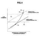
- intersection point pressure Pa is set at a pressure not greater than the suction pressure Ps during an operation mode when the refrigerating power is prioritized (see continuous line in Fig. 4). Contrary to this, the intersection point pressure Pa is set at a pressure not less than the suction pressure Ps during a saving mode (see dashed line in Fig. 4).
- control valve characteristic C/ V does not intersect with the open valve characteristic TXV, to thereby prevent an interfered control area "d" from occurring which is responsible for failures such as hunting and the like.
- the set value of the expansion valve 5 is lowered, to thereby cause a preferable valve opening (likely to be restricted).
- the thus obtained preferable valve opening contributes toward causing the proper super heat, to thereby improve the refrigerating power.
- the refrigerant flowrate is reduced, to thereby improve a saving mode of the variable displacement compressor 1.
- valve opening when a low load is applied, the valve opening is likely to be open.
- the thus obtained valve opening contributes toward causing a proper super heat, and a proper refrigerant flowrate is obtained throughout the entire area of the evaporator 7.
- the evaporator 7 is improved in terms of temperature characteristic (no deviation in temperature distribution), and an effective refrigeration is achieved.
- Fig. 5 there is provided a graph showing the open valve characteristic TXV of the expansion valve 5, and the control valve characteristic C/V of the control valve 9 built in the variable displacement compressor 1, according to a second preferred embodiment of the present invention.
- the open valve characteristic TXV of the expansion valve 5 features substantially a horizontal graph, by restricting constantly the port area A of the port 11. Thereby, the open valve characteristic TXV is small in terms of dependency on high pressure. Contrary to this, the control valve characteristic C/V features a downward slope toward higher pressure, in other words, the downward slope in accordance with the discharge pressure Pd which gets higher gradually.
- the intersection point P is set in the first intersection zone A-1 (or the first non-operation area A-1) that is out of the operation area B, to thereby prevent failures from occurring such as hunting and the like.
- Fig. 6 there is provided a graph showing the open valve characteristic TXV of the expansion valve 5, and the control valve characteristic C/V of the control valve 9 built in the variable displacement compressor 1, according to a third preferred embodiment of the present invention.
- the open valve characteristic TXV features a downward slope toward higher pressure, by increasing the port area A of the port 11.
- the control valve characteristic C/V also features a downward slope toward high pressure, in other words, the downward slope in accordance with the discharge pressure Pd which gets higher gradually.
- the open valve characteristic TXV is not parallel relative to the control valve characteristic C/V.
- the intersection point P is set in the second intersection zone A-2 (or the second non-operation area A-2) that is out of the operation area B, to thereby prevent failures from occurring such as hunting and the like.
Landscapes
- Engineering & Computer Science (AREA)
- Physics & Mathematics (AREA)
- Mechanical Engineering (AREA)
- Thermal Sciences (AREA)
- General Engineering & Computer Science (AREA)
- Fluid Mechanics (AREA)
- Control Of Positive-Displacement Pumps (AREA)
- Temperature-Responsive Valves (AREA)
- Compressors, Vaccum Pumps And Other Relevant Systems (AREA)
Abstract
Description
- The present invention relates to an expansion valve for a refrigerating cycle which is suitable for an air conditioning system for a motor vehicle.
- Generally, the air conditioning system for the motor vehicle is constituted of the refrigerating cycle in which a refrigerant discharged from a compressor is returned to the compressor by way of a condenser, the expansion valve and an evaporator.
- The expansion valve is so designed as to control super heat by evaporation temperature at an outlet of the evaporator and a pressure (low pressure) at the outlet of the evaporator. Thereby, the expansion valve is so made as to be free from being influenced by any high pressure which may cause a disturbance.
- As is seen in Fig. 7, the expansion valve shows an open valve characteristic TXV which features substantially a horizontal graph. In other words, the open valve characteristic TXV is not dependent on the high pressure.
- The open valve characteristic TXV of the expansion valve in Fig. 7 is obtained at an evaporator outlet temperature Te of 0° C. In Fig. 7, the ordinate is an evaporator outlet pressure Pe (more specifically, Pe out), while the abscissa is a discharge pressure Pd. There is defined an expansion valve closed zone on substantially an upper side of the open valve characteristic TXV. Contrary to this, there is defined an expansion valve open zone on substantially a lower side of the open valve characteristic TXV. Moreover, as is seen in Fig. 7, on substantially a left side and substantially a right side of an operation area B, there are defined, respectively, a first non-operation area A-1 and a second non-operation area A-2, in each of which the compressor does not operate.
- Furthermore, Fig. 7 shows a control valve characteristic C/V featuring a downward slope in accordance with the discharge pressure Pd which gets higher gradually. The control valve characteristic C/V is the one that is obtained when a variable displacement compressor equipped with a control valve is combined with the expansion valve that is set at the open valve characteristic TXV featuring the substantially horizontal graph. In the expansion valve closed zone, there is caused an interfered control area "d" as is depicted by diagonal lines in Fig. 7.
- Failures such as hunting and the like may occur, for example, under the following three conditions combined: 1. The expansion valve is set at 5 kg/cm2G (namely, in the interfered control area "d"). 2. Being in the expansion valve closed zone. 3. The compressor is likely to pull the refrigerant forcibly.
- In order to prevent such failures from occurring, there is provided one possible solution, that is, to make the control valve characteristic C/V non-linear so that the interfered control area "d" does not occur up to an intersection point P. However, such solution complicates the constitution of the control valve characteristic C/V.
- For preventing, with ease, the interfered control area "d" from occurring, the open valve characteristic TXV of the expansion valve is set higher than the control valve characteristic C/V, as is depicted by a dashed line in Fig. 7. In this case, however, the valve opening of the expansion valve gets large when the discharge pressure is high (high load applied) since the control valve characteristic C/V is included in the expansion valve open zone.
- When the valve opening of the expansion valve gets large, the refrigerant flowrate will increase. Thereby, it becomes impossible to take the proper super heat, and the refrigerating power is deteriorated. Simultaneously with this, consumption (power) of the variable displacement compressor is increased, thus ending up an increase in cost (not preferable).
- It is, therefore, an object of the present invention to provide an expansion valve for a refrigerating cycle for solving the above mentioned problems.
- According to a first aspect of the present invention, there is provided a refrigerating cycle comprising a condenser, an evaporator, a variable displacement compressor, and an expansion valve. The variable displacement compressor is connected between the condenser and the evaporator to form the refrigerating cycle, and comprises a control valve designed to provide a control valve characteristic sloping downward with increase in a discharge pressure. The expansion valve is connected between the condenser and the evaporator, to return a refrigerant from the condenser through the evaporator to the variable displacement compressor, and designed to provide an open valve characteristic whose slope is approximately equal to the downward slope of the control valve characteristic.
- According to one of a second aspect and a third aspect of the present invention, there is provided a refrigerating cycle comprising a condenser, an evaporator, a variable displacement compressor, and an expansion valve. The variable displacement compressor is connected between the condenser and the evaporator to form the refrigerating cycle, and comprises a control valve designed to provide a control valve characteristic sloping downward with increase in a discharge pressure. Furthermore, the variable displacement compressor is adapted to operate in an operation area defined between a first non-operation area and a second non-operation area opposite to the first non-operation area, the second non-operation area defining the discharge pressure higher than the discharge pressure that is defined in the operation area. The expansion valve is connected between the condenser and the evaporator, to return a refrigerant from the condenser through the evaporator to the variable displacement compressor, and designed to provide an open valve characteristic which intersects, at an intersection point defined in one of the first non-operation area and the second non-operation area of the variable displacement compressor, with the control valve characteristic of the control valve.
-
- Fig. 1 is a graph showing an open valve characteristic TXV of an
expansion valve 5, and a control valve characteristic C/V of avariable displacement compressor 1, according to a first preferred embodiment of the present invention; - Fig. 2 is a block diagram of a refrigerating cycle;
- Fig. 3 is a schematic diagram of the
expansion valve 5; - Fig. 4 is a graph showing an intersection point pressure Pa relative to a pressure control line;
- Fig. 5 is a graph showing an intersection point P (the open valve characteristic TXV intersecting with the control valve characteristic C/V) disposed in a first non-operation area A-1, according to a second preferred embodiment of the present invention;
- Fig. 6 is a graph showing the intersection point P disposed in a second non-operation area A-2, according to a third preferred embodiment of the present invention; and
- Fig. 7 (similar to Fig. 1) is a graph showing an open valve characteristic TXV of an expansion valve and a control valve characteristic C/V of a variable displacement compressor, according to a related art.
-
- As is seen in Fig 1 through Fig. 4, there is provided an
expansion valve 5 for a refrigerating cycle and data related thereto, according to a first preferred embodiment of the present invention. - As is seen in Fig. 2, there is provided the refrigerating cycle of an air conditioning system for a motor vehicle. A refrigerant is discharged from a
variable displacement compressor 1, and is then returned to thevariable displacement compressor 1 by way of acondenser 3, theexpansion valve 5 and anevaporator 7. - A control valve 9 is built in the
variable displacement compressor 1. When being combined with the expansion valve 5 (to be mentioned afterwards), the variable displacement compressor 1 (control valve 9) shows a control valve characteristic C/V as is seen in Fig. 1. - In Fig. 1, the ordinate is a suction pressure Ps (or an evaporator outlet pressure Pe out), while the abscissa is a discharge pressure Pd (or an expansion valve inlet pressure Pex). The
variable displacement compressor 1 operates in an operation area B. There is defined a first intersection zone A-1 substantially on a left side of the operation area B in Fig. 1. In the first intersection zone A-1, the suction pressure Ps (low pressure) is equal to the discharge pressure Pd (high pressure), to thereby make thevariable displacement compressor 1 stay at rest (not operating). There is provided a second intersection zone A-2 substantially on a right side of the operation area B in Fig. 1. In the second intersection zone A-2, the discharge pressure Pd is so high as to disengage a clutch, to thereby make thevariable displacement compressor 1 stay at rest (not operating). This summarizes that the first intersection zone A-1 disposed substantially on the left side of the operation area B in Fig. 1 is defined as a first non-operation area A-1, while the second intersection zone A-2 disposed substantially on the right side of the operation area B in Fig. 1 is defined as a second non-operation area A-2. - As is seen in Fig. 3, the
expansion valve 5 has aport 11, and aball valve 13 for controlling a port area A of theport 11. A spring pressure is applied upwardly to theball valve 13 from anenergizing spring 15, while a diaphragm pressure is applied downwardly to theball valve 13 from adiaphragm 19 by way of ashaft 17. The spring pressure of the energizingspring 15 is arbitrarily adjustable by using an adjustingmeasure 21 such as screw and the like. The diaphragm pressure is variable according to pressure and temperature of a refrigerant at an outlet of theevaporator 7. Then, a differential pressure between the spring pressure and the diaphragm pressure contributes toward obtaining a variable set value of theexpansion valve 5. - As is seen in Fig. 1, the
expansion valve 5 combined with thevariable displacement compressor 1 shows an open valve characteristic TXV that has substantially the same slope as that of the control valve characteristic C/V. - The open valve characteristic TXV of the
expansion valve 5 in Fig. 1 is a control characteristic when an evaporator outlet temperature Te of the refrigerant at an outlet of theevaporator 7 is 0° C. - Namely, the open valve characteristic TXV having substantially the same slope as that of the control valve characteristic C/V as is seen in Fig. 1 can be obtained by increasing the
port 11 in diameter or by decreasing thediaphragm 19 in diameter. - More specifically, the following expressions are obtained using an effective diameter D of the
diaphragm 19, a diaphragm pressure PD, a shaft area S, the port area A, a spring constant K (of the energizing spring 15), a lift X (an extent that theball valve 13 is lifted), a load FD applied to thediaphragm 19, and a load FX applied to the ball valve 13: - In the expression (1) above, FX = FD (equilibrium). Thereby, the following expression (2) is obtained:
- When Pe in = Pe out, the following expression (3) is obtained:
- Thus, the following expression (4) is obtained:
spring 15. - With the expressions above, it is evident that increasing the port area A of the
port 11 or decreasing the effective diameter D of thediaphragm 19 contributes toward allowing, with ease, the open valve characteristic TXV to have substantially the same slope as that of the control valve characteristic C/V. - In this case, a relation of the open valve characteristic TXV of the
expansion valve 5 relative to the control valve characteristic C/V of the control valve 9 is described below. As is seen in Fig. 4, the ordinate is a low pressure, while the abscissa is a temperature of the refrigerant (at the outlet of the evaporator 7). In order to take a proper super heat, an intersection point pressure Pa (where a refrigerant saturation line WL intersects with the open valve characteristic TXV of the expansion valve 5) is defined, in the following manner, with respect to a control line (the suction pressure Ps) of the variable displacement compressor 1: - The intersection point pressure Pa is set at a pressure not greater than the suction pressure Ps during an operation mode when the refrigerating power is prioritized (see continuous line in Fig. 4). Contrary to this, the intersection point pressure Pa is set at a pressure not less than the suction pressure Ps during a saving mode (see dashed line in Fig. 4).
- With the
expansion valve 5 for the refrigerating cycle thus constituted, the control valve characteristic C/ V does not intersect with the open valve characteristic TXV, to thereby prevent an interfered control area "d" from occurring which is responsible for failures such as hunting and the like. - In addition, when a high load is applied, the set value of the
expansion valve 5 is lowered, to thereby cause a preferable valve opening (likely to be restricted). The thus obtained preferable valve opening contributes toward causing the proper super heat, to thereby improve the refrigerating power. Simultaneously with this, the refrigerant flowrate is reduced, to thereby improve a saving mode of thevariable displacement compressor 1. - On the other hand, when a low load is applied, the valve opening is likely to be open. The thus obtained valve opening contributes toward causing a proper super heat, and a proper refrigerant flowrate is obtained throughout the entire area of the
evaporator 7. Thereby, theevaporator 7 is improved in terms of temperature characteristic (no deviation in temperature distribution), and an effective refrigeration is achieved. - As is seen in Fig. 5, there is provided a graph showing the open valve characteristic TXV of the
expansion valve 5, and the control valve characteristic C/V of the control valve 9 built in thevariable displacement compressor 1, according to a second preferred embodiment of the present invention. - The open valve characteristic TXV of the
expansion valve 5 features substantially a horizontal graph, by restricting constantly the port area A of theport 11. Thereby, the open valve characteristic TXV is small in terms of dependency on high pressure. Contrary to this, the control valve characteristic C/V features a downward slope toward higher pressure, in other words, the downward slope in accordance with the discharge pressure Pd which gets higher gradually. In the second preferred embodiment, the intersection point P is set in the first intersection zone A-1 (or the first non-operation area A-1) that is out of the operation area B, to thereby prevent failures from occurring such as hunting and the like. - Moreover, as is seen in Fig. 6, there is provided a graph showing the open valve characteristic TXV of the
expansion valve 5, and the control valve characteristic C/V of the control valve 9 built in thevariable displacement compressor 1, according to a third preferred embodiment of the present invention. - The open valve characteristic TXV features a downward slope toward higher pressure, by increasing the port area A of the
port 11. On the other hand, the control valve characteristic C/V also features a downward slope toward high pressure, in other words, the downward slope in accordance with the discharge pressure Pd which gets higher gradually. In addition, the open valve characteristic TXV is not parallel relative to the control valve characteristic C/V. In the third preferred embodiment, the intersection point P is set in the second intersection zone A-2 (or the second non-operation area A-2) that is out of the operation area B, to thereby prevent failures from occurring such as hunting and the like.
Claims (11)
- A refrigerating cycle comprising:a condenser;an evaporator;a variable displacement compressor connected between the condenser and the evaporator to form the refrigerating cycle, the variable displacement compressor comprising a control valve designed to provide a control valve characteristic sloping downward with increase in a discharge pressure; andan expansion valve connected between the condenser and the evaporator, to return a refrigerant from the condenser through the evaporator to the variable displacement compressor, and designed to provide an open valve characteristic whose slope is approximately equal to the downward slope of the control valve characteristic.
- The refrigerating cycle as claimed in claim 1, in which the control valve characteristic of the control valve is a relationship between the discharge pressure on an outlet side of the variable displacement compressor and a suction pressure on an inlet side of the variable displacement compressor, while the open valve characteristic of the expansion valve is a relationship between an inlet pressure on an inlet side of the expansion valve and an outlet pressure on an outlet side of the expansion valve, and in which the variable displacement compressor is adapted to operate in an operation area.
- The refrigerating cycle as claimed in claim 2, in which the expansion valve comprises a port defining a port area, and the expansion valve further comprises a diaphragm defining a diameter, and in which at least one of the port area and the diameter is so sized that the open valve characteristic of the expansion valve is higher than the control valve characteristic of the control valve of the variable displacement compressor.
- The refrigerating cycle as claimed in claim 3, in which the port area of the port of the expansion valve is increased so as to allow the expansion valve to provide the open valve characteristic whose slope is approximately equal to the downward slope of the control valve characteristic of the control valve.
- The refrigerating cycle as claimed in claim 3, in which the diameter of the diaphragm of the expansion valve is decreased so as to allow the expansion valve to provide the open valve characteristic whose slope is approximately equal to the downward slope of the control valve characteristic of the control valve.
- A refrigerating cycle comprising:a condenser;an evaporator;a variable displacement compressor connected between the condenser and the evaporator to form the refrigerating cycle, the variable displacement compressor comprising a control valve designed to provide a control valve characteristic sloping downward with increase in a discharge pressure, the variable displacement compressor being adapted to operate in an operation area defined between a first non-operation area and a second non-operation area opposite to the first non-operation area, the second non-operation area defining the discharge pressure higher than the discharge pressure that is defined in the operation area; andan expansion valve connected between the condenser and the evaporator, to return a refrigerant from the condenser through the evaporator to the variable displacement compressor, and designed to provide an open valve characteristic which intersects, at an intersection point defined in one of the first non-operation area and the second non-operation area of the variable displacement compressor, with the control valve characteristic of the control valve.
- The refrigerating cycle as claimed in claim 6, in which the control valve characteristic of the control valve is a relationship between the discharge pressure on an outlet side of the variable displacement compressor and a suction pressure on an inlet side of the variable displacement compressor, while the open valve characteristic of the expansion valve is a relationship between an inlet pressure on an inlet side of the expansion valve and an outlet pressure on an outlet side of the expansion valve.
- The refrigerating cycle as claimed in claim 7, in which the expansion valve comprises a port defining a port area, the port area being restricted constantly so as to allow the expansion valve to provide the open valve characteristic whose slope is less inclined than the downward slope of the control valve characteristic of the control valve.
- The refrigerating cycle as claimed in claim 8, in which the open valve characteristic of the expansion valve and the control valve characteristic of the control valve intersect with each other at the intersection point defined in the first non-operation area.
- The refrigerating cycle as claimed in claim 7, in which the expansion valve comprises a port defining a port area, the port area being increased so as to allow the expansion valve to provide the open valve characteristic whose slope is more inclined than the downward slope of the control valve characteristic of the control valve.
- The refrigerating cycle as claimed in claim 10, in which the open valve characteristic of the expansion valve and the control valve characteristic of the control valve intersect with each other at the intersection point defined in the second non-operation area.
Applications Claiming Priority (2)
| Application Number | Priority Date | Filing Date | Title |
|---|---|---|---|
| JP2000126450 | 2000-04-26 | ||
| JP2000126450A JP2001304723A (en) | 2000-04-26 | 2000-04-26 | Expansion valve for refrigeration cycle |
Publications (2)
| Publication Number | Publication Date |
|---|---|
| EP1150079A1 true EP1150079A1 (en) | 2001-10-31 |
| EP1150079B1 EP1150079B1 (en) | 2005-10-05 |
Family
ID=18636231
Family Applications (1)
| Application Number | Title | Priority Date | Filing Date |
|---|---|---|---|
| EP01109579A Expired - Lifetime EP1150079B1 (en) | 2000-04-26 | 2001-04-18 | Refrigerating cycle with an expansion valve |
Country Status (4)
| Country | Link |
|---|---|
| US (1) | US6334322B2 (en) |
| EP (1) | EP1150079B1 (en) |
| JP (1) | JP2001304723A (en) |
| DE (1) | DE60113759T2 (en) |
Families Citing this family (2)
| Publication number | Priority date | Publication date | Assignee | Title |
|---|---|---|---|---|
| US6543241B2 (en) * | 2000-12-04 | 2003-04-08 | Mikhail Levitin | Refrigerant feed device |
| KR101884153B1 (en) | 2018-03-29 | 2018-07-31 | 노상호 | Environmental Disaster Information Offering LED Mood Lamp |
Citations (4)
| Publication number | Priority date | Publication date | Assignee | Title |
|---|---|---|---|---|
| US3875757A (en) * | 1972-01-19 | 1975-04-08 | Saginomiya Seisakusho Inc | Expansion valve for preventing hunting in refrigeration system |
| US3952535A (en) * | 1973-07-27 | 1976-04-27 | White-Westinghouse Corporation | Automatic expansion valve for refrigerant |
| WO2000037838A1 (en) * | 1998-12-23 | 2000-06-29 | BELIMO AIRCONTROLs (USA), INC. | Control valve with modified characteristics |
| EP1069385A2 (en) * | 1999-07-12 | 2001-01-17 | TGK Co., Ltd. | An expansion valve in a refrigerating cycle |
Family Cites Families (5)
| Publication number | Priority date | Publication date | Assignee | Title |
|---|---|---|---|---|
| US3367130A (en) * | 1966-02-23 | 1968-02-06 | Sporlan Valve Co | Expansion valve and refrigeration system responsive to subcooling temperature |
| JPS5494149A (en) * | 1978-01-06 | 1979-07-25 | Hitachi Ltd | Freezer |
| JPH09196478A (en) * | 1996-01-23 | 1997-07-31 | Nippon Soken Inc | Refrigeration cycle |
| JP2000111176A (en) * | 1998-10-05 | 2000-04-18 | Toyota Autom Loom Works Ltd | Air conditioner |
| US6105680A (en) * | 1999-05-28 | 2000-08-22 | Caterpillar S.A.R.L. | Locking device for a spring trip mechanism |
-
2000
- 2000-04-26 JP JP2000126450A patent/JP2001304723A/en active Pending
-
2001
- 2001-04-18 EP EP01109579A patent/EP1150079B1/en not_active Expired - Lifetime
- 2001-04-18 DE DE60113759T patent/DE60113759T2/en not_active Expired - Fee Related
- 2001-04-19 US US09/837,485 patent/US6334322B2/en not_active Expired - Fee Related
Patent Citations (4)
| Publication number | Priority date | Publication date | Assignee | Title |
|---|---|---|---|---|
| US3875757A (en) * | 1972-01-19 | 1975-04-08 | Saginomiya Seisakusho Inc | Expansion valve for preventing hunting in refrigeration system |
| US3952535A (en) * | 1973-07-27 | 1976-04-27 | White-Westinghouse Corporation | Automatic expansion valve for refrigerant |
| WO2000037838A1 (en) * | 1998-12-23 | 2000-06-29 | BELIMO AIRCONTROLs (USA), INC. | Control valve with modified characteristics |
| EP1069385A2 (en) * | 1999-07-12 | 2001-01-17 | TGK Co., Ltd. | An expansion valve in a refrigerating cycle |
Also Published As
| Publication number | Publication date |
|---|---|
| DE60113759D1 (en) | 2006-02-16 |
| US6334322B2 (en) | 2002-01-01 |
| EP1150079B1 (en) | 2005-10-05 |
| JP2001304723A (en) | 2001-10-31 |
| US20010035017A1 (en) | 2001-11-01 |
| DE60113759T2 (en) | 2006-04-27 |
Similar Documents
| Publication | Publication Date | Title |
|---|---|---|
| CN111692736B (en) | Control method of electronic expansion valve and air conditioning system | |
| US6351959B1 (en) | Refrigerating cycle with a by-pass line | |
| US5867995A (en) | Electronic control of refrigeration systems | |
| CA2436226A1 (en) | Self tuning pull-down fuzzy logic temperature control for refrigeration systems | |
| JPH0694953B2 (en) | Closed refrigeration circuit | |
| EP0602996B1 (en) | Dual capacity thermal expansion valve | |
| US20150027149A1 (en) | Electric expansion valve control for a refrigeration system | |
| JP2004142701A (en) | Refrigeration cycle | |
| US7201008B2 (en) | Vapor compression system performance enhancement and discharge temperature reduction in the unloaded mode of operation | |
| US11499766B2 (en) | Electric expansion valve, a heat exchange system and a method of controlling the electric expansion valve | |
| EP1150079B1 (en) | Refrigerating cycle with an expansion valve | |
| US5277364A (en) | Dual capacity thermal expansion valve | |
| JP2004093106A (en) | Expansion valve | |
| US6216477B1 (en) | Regulating device for air conditioner refrigerant circuit | |
| JP2006097972A (en) | Accumulator refrigeration cycle | |
| US8424328B2 (en) | Suction valve pulse width modulation control based on evaporator or condenser pressure | |
| JPH10185343A (en) | Refrigeration equipment | |
| EP1388719A3 (en) | Air conditioning system | |
| JPH109644A (en) | Air conditioner | |
| WO2019239587A1 (en) | Refrigeration cycle device | |
| JPH08296883A (en) | Air conditioner | |
| JPH0810088B2 (en) | Air conditioner | |
| JPH10325479A (en) | Refrigeration equipment, refrigerant flow compensation bypass valve and temperature expansion valve | |
| CN120557755B (en) | Control method, heat pump unit and air conditioner | |
| JP2003028516A (en) | Refrigeration cycle control device |
Legal Events
| Date | Code | Title | Description |
|---|---|---|---|
| PUAI | Public reference made under article 153(3) epc to a published international application that has entered the european phase |
Free format text: ORIGINAL CODE: 0009012 |
|
| 17P | Request for examination filed |
Effective date: 20010418 |
|
| AK | Designated contracting states |
Kind code of ref document: A1 Designated state(s): AT BE CH CY DE DK ES FI FR GB GR IE IT LI LU MC NL PT SE TR Kind code of ref document: A1 Designated state(s): DE FR GB |
|
| AX | Request for extension of the european patent |
Free format text: AL;LT;LV;MK;RO;SI |
|
| AKX | Designation fees paid |
Free format text: DE FR GB |
|
| 17Q | First examination report despatched |
Effective date: 20031216 |
|
| GRAP | Despatch of communication of intention to grant a patent |
Free format text: ORIGINAL CODE: EPIDOSNIGR1 |
|
| RTI1 | Title (correction) |
Free format text: REFRIGERATING CYCLE WITH AN EXPANSION VALVE |
|
| GRAS | Grant fee paid |
Free format text: ORIGINAL CODE: EPIDOSNIGR3 |
|
| GRAA | (expected) grant |
Free format text: ORIGINAL CODE: 0009210 |
|
| AK | Designated contracting states |
Kind code of ref document: B1 Designated state(s): DE FR GB |
|
| REG | Reference to a national code |
Ref country code: GB Ref legal event code: FG4D |
|
| REF | Corresponds to: |
Ref document number: 60113759 Country of ref document: DE Date of ref document: 20060216 Kind code of ref document: P |
|
| ET | Fr: translation filed | ||
| PLBE | No opposition filed within time limit |
Free format text: ORIGINAL CODE: 0009261 |
|
| STAA | Information on the status of an ep patent application or granted ep patent |
Free format text: STATUS: NO OPPOSITION FILED WITHIN TIME LIMIT |
|
| 26N | No opposition filed |
Effective date: 20060706 |
|
| PGFP | Annual fee paid to national office [announced via postgrant information from national office to epo] |
Ref country code: DE Payment date: 20080424 Year of fee payment: 8 Ref country code: FR Payment date: 20080312 Year of fee payment: 8 |
|
| PGFP | Annual fee paid to national office [announced via postgrant information from national office to epo] |
Ref country code: GB Payment date: 20080423 Year of fee payment: 8 |
|
| GBPC | Gb: european patent ceased through non-payment of renewal fee |
Effective date: 20090418 |
|
| REG | Reference to a national code |
Ref country code: FR Ref legal event code: ST Effective date: 20091231 |
|
| PG25 | Lapsed in a contracting state [announced via postgrant information from national office to epo] |
Ref country code: DE Free format text: LAPSE BECAUSE OF NON-PAYMENT OF DUE FEES Effective date: 20091103 |
|
| PG25 | Lapsed in a contracting state [announced via postgrant information from national office to epo] |
Ref country code: FR Free format text: LAPSE BECAUSE OF NON-PAYMENT OF DUE FEES Effective date: 20091222 Ref country code: GB Free format text: LAPSE BECAUSE OF NON-PAYMENT OF DUE FEES Effective date: 20090418 |