EP1150017A2 - Blower - Google Patents
Blower Download PDFInfo
- Publication number
- EP1150017A2 EP1150017A2 EP01302882A EP01302882A EP1150017A2 EP 1150017 A2 EP1150017 A2 EP 1150017A2 EP 01302882 A EP01302882 A EP 01302882A EP 01302882 A EP01302882 A EP 01302882A EP 1150017 A2 EP1150017 A2 EP 1150017A2
- Authority
- EP
- European Patent Office
- Prior art keywords
- base
- chamber
- blower
- motor
- raceway
- Prior art date
- Legal status (The legal status is an assumption and is not a legal conclusion. Google has not performed a legal analysis and makes no representation as to the accuracy of the status listed.)
- Granted
Links
Images

Classifications
-
- F—MECHANICAL ENGINEERING; LIGHTING; HEATING; WEAPONS; BLASTING
- F04—POSITIVE - DISPLACEMENT MACHINES FOR LIQUIDS; PUMPS FOR LIQUIDS OR ELASTIC FLUIDS
- F04D—NON-POSITIVE-DISPLACEMENT PUMPS
- F04D25/00—Pumping installations or systems
- F04D25/02—Units comprising pumps and their driving means
- F04D25/08—Units comprising pumps and their driving means the working fluid being air, e.g. for ventilation
-
- F—MECHANICAL ENGINEERING; LIGHTING; HEATING; WEAPONS; BLASTING
- F04—POSITIVE - DISPLACEMENT MACHINES FOR LIQUIDS; PUMPS FOR LIQUIDS OR ELASTIC FLUIDS
- F04D—NON-POSITIVE-DISPLACEMENT PUMPS
- F04D25/00—Pumping installations or systems
- F04D25/02—Units comprising pumps and their driving means
- F04D25/06—Units comprising pumps and their driving means the pump being electrically driven
- F04D25/0606—Units comprising pumps and their driving means the pump being electrically driven the electric motor being specially adapted for integration in the pump
- F04D25/0613—Units comprising pumps and their driving means the pump being electrically driven the electric motor being specially adapted for integration in the pump the electric motor being of the inside-out type, i.e. the rotor is arranged radially outside a central stator
- F04D25/0633—Details of the magnetic circuit
-
- H—ELECTRICITY
- H02—GENERATION; CONVERSION OR DISTRIBUTION OF ELECTRIC POWER
- H02K—DYNAMO-ELECTRIC MACHINES
- H02K11/00—Structural association of dynamo-electric machines with electric components or with devices for shielding, monitoring or protection
- H02K11/30—Structural association with control circuits or drive circuits
- H02K11/33—Drive circuits, e.g. power electronics
-
- H—ELECTRICITY
- H02—GENERATION; CONVERSION OR DISTRIBUTION OF ELECTRIC POWER
- H02K—DYNAMO-ELECTRIC MACHINES
- H02K7/00—Arrangements for handling mechanical energy structurally associated with dynamo-electric machines, e.g. structural association with mechanical driving motors or auxiliary dynamo-electric machines
- H02K7/14—Structural association with mechanical loads, e.g. with hand-held machine tools or fans
-
- H—ELECTRICITY
- H02—GENERATION; CONVERSION OR DISTRIBUTION OF ELECTRIC POWER
- H02K—DYNAMO-ELECTRIC MACHINES
- H02K5/00—Casings; Enclosures; Supports
- H02K5/04—Casings or enclosures characterised by the shape, form or construction thereof
- H02K5/10—Casings or enclosures characterised by the shape, form or construction thereof with arrangements for protection from ingress, e.g. water or fingers
Definitions
- the present invention relates mainly to a blower suitable for cooling office automation equipment.
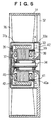
- a typical blower for cooling office automation equipment has for example a structure as shown in Fig. 5 in which the blower includes a base 33 provided and supported at the central portion of a frame 31 by means of stays 32, a rotor member 35 rotatably journalled by means of a bearing apparatus 34 provided on the front side of the base at the central portion thereof, and an impeller 37 having a plurality of blades 36 provided on an outer peripheral flange 37a, the impeller is mounted on the rotor member 35.
- a printed circuit board 39 including electrical components 38 for controlling the motor is secured to an iron core holder 40a of a stator 40 by means of screws 41, and is accommodated within a parts storing portion 42 surrounded by a flange 33a extending forward from the outer periphery of the base 33.
- the reference numeral 43 designates a magnet or magnets mounted on the inner surface of the outer peripheral flange of the rotor member 35 so as to be opposite the outer peripheral surface of the stator.
- the impeller 37 will rotate upon energizing of the motor, and at least a portion of thus produced wind penetrates through a clearance A defined between a rear end edge of the outer peripheral flange 37a of the impeller 37 and a front end edge of the outer peripheral flange 33a of the base 33 into the motor.
- the object of the present invention is to provide a blower in which electrical components such as printed circuit board or electronic parts are isolated from the air flowing through the blower to protect these components from moisture, dirt, dust or other harmful gas or substances contained in the air, and to prevent the degradation of the insulating property such as the electric insulation or dielectric strength of these components.
- blower having an impeller adapted to be rotated by means of a motor in accordance with claim 1, the blower comprising:
- the blower in accordance with claim 2 has an impeller adapted to be rotated by means of a motor, the blower comprising:
- the chamber for accommodating electrical components is formed by the base having a flange extending backwards from the outer periphery thereof to form a cylindrical body with a bottom, the chamber has an opening at the rear thereof, and the rear opening of the base is occluded or covered by the cover which is detachably mounted by screws on the base.
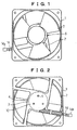
- a blower body or a frame 1 of synthetic resin includes a base 4 supported integrally therewith at the central portion thereof through a few stays 2.
- a motor 3 is mounted on the front side of the base 4.
- a distal end of a spindle shaft 3a of the motor 3 is fitted and secured in a central hub 6c protruding backwards from a front face plate 6a of an impeller 6.
- the impeller 6 includes the front face plate 6a, a flange 6b extending backwards from the outer periphery of the plate, and a suitable number of blades 7 provided around the outer periphery of the flange.
- the base 4 has a flange 4a extending backwards from the outer periphery thereof to form a cylindrical body with a bottom having an opening at the rear end thereof.
- the cylindrical body is covered by a cover 10 to define a sealed chamber 11 for accommodating electric components.
- the accommodating chamber is adapted to accommodate the electrical components such as the printed circuit board 12 or other electronic parts 13.
- a plurality of internally threaded bosses 4b extend backwards (rightwards in the drawings) from the bottom of the base 4 to detachably mount the cover 10 to the base by threadably engaging screws 9 with the internal threads of the bosses.
- the reference numeral 14 designates leads to a printed circuit board, and the reference numeral 14a designates a connector of the leads 14.
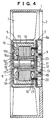
- blower including a motor of an outer rotor type is shown in Fig. 4.
- the base 4 has a sleeve-like bearing holder 15 formed integrally therewith extending forwards (leftwards in the drawings) therefrom.
- the bearing holder 15 is provided therearound with a stator 16 comprising an iron core 16a and a coil 16b. Further, a sleeve 17 forming an outer ring is accommodated with in the bearing holder 15.
- the sleeve 17 includes a spindle shaft 18 journalled by means of a bearing apparatus as described hereinbelow.
- a distal end of the spindle shaft protruding from the sleeve 17 fits within a hub 5c extending from a central aperture formed on a front face plate 5a of a yoke 5 and is secured thereto.
- the yoke 5 has a flange 5b extending backwards from the outer periphery of the front face plate 5a.
- a magnet or magnets 18 corresponding to the stator 16 are provided on the inner peripheral surface of the flange.
- An impeller 6 is secured to the front face plate 5a of the rotor member 5 by means of rivets 8 or any other means.
- a lead wire 19 leading to the coil 16b of the stator 16 extends through a bore formed through a leg 21 of an iron core holder 20 of the stator to the circuit formed on the printed circuit board 12 and connected thereto.
- the reference numeral 22 designates a washer of synthetic resin mounted around the spindle shaft 18 for preventing the dirt or dust from entering into the bearing apparatus.
- a bearing apparatus of various structures can be adopted for journaling the spindle shaft 18.
- the bearing apparatus of this embodiment comprises a stepped shaft 18 including a larger diameter portion and a reduced diameter portion, an inner ring 23 fitted to and secured over the reduced diameter portion of the shaft, a first raceway formed around the outer periphery of the larger diameter portion, a second raceway formed on the inner peripheral surface of the sleeve 17, a plurality of balls of metallic or ceramic material of a first row interposed between the first and second raceways, a third raceway formed around the outer periphery of the inner ring 23, a fourth raceway formed on the inner peripheral surface of the sleeve, and a plurality of balls of metallic or ceramic material of a second row interposed between the third and fourth raceways.
- the balls of the first and second row are equal in their diameter.
- the balls of ceramic material have high hardness, and provide good wear resistance and durability.
- a blower including a bearing apparatus in which balls of ceramic material are incorporated can be used at high rotation speeds and can be operated relatively quietly.
- a blower in according with the present invention is provided at the rear side of the base with a chamber for accommodating electrical components so that the printed circuit board or electronic parts can be protected from moisture, dirt, dust or other harmful gas or substances contained in a draught produced through the wind tunnel portion, and the degradation of the insulating property such as the electric insulation or dielectric property can be avoided.
- the reliability of the blower or the equipment incorporated within the blower can be enhanced.
- the blower claimed in claim 2 is provided with the bearing apparatus including a stepped shaft having a raceway which is formed directly on the larger diameter portion thereof.
- a conventional ball bearing including both inner and outer rings is not necessary, and the diameter of the larger diameter portion of the shaft can be enlarged by the sum of the thicknesses of the inner and outer rings of the ball bearing, and the diameter of the reduced diameter portion of the shaft can also be enlarged by the thickness of the outer ring of the ball bearing, i.e. a generally thicker shaft can be used.
- blower including a shaft of higher rigidity, good durability, lower rotational run-out or play, and quiet operation can be provided.
- the bearing apparatus includes one sleeve serving as outer rings and one inner ring fitted around the reduced diameter portion of the spindle shaft, so that the number of components of the bearing apparatus can be reduced to decrease the cost thereof.
Landscapes
- Engineering & Computer Science (AREA)
- Power Engineering (AREA)
- Mechanical Engineering (AREA)
- General Engineering & Computer Science (AREA)
- Microelectronics & Electronic Packaging (AREA)
- Structures Of Non-Positive Displacement Pumps (AREA)
- Connection Of Motors, Electrical Generators, Mechanical Devices, And The Like (AREA)
Abstract
Description
Claims (5)
- A blower having an impeller (6) adapted to be rotated by means of a motor (3) comprising:a base (4) for supporting the motor (3), the base (4) is provided and supported at the central portion of a frame (1) by means of stays (2); anda chamber (11) for accommodating electrical components (12, 13) formed in the base (4), a back portion of the chamber (11) adapted to be sealed by a removable cover (10).
- A blower having an impeller (6) adapted to be rotated by means of a motor (2) comprising:a base (4) for supporting the motor (3), the base (4) is provided and supported at the central portion of a frame (1) by means of stays (2) ;a bearing apparatus for supporting a central portion of the impeller (6), the bearing apparatus includinga sleeve (17),a stepped shaft (18) including a larger diameter portion and a reduced diameter portion,a first raceway formed at an appropriate position around an outer peripheral surface of the larger diameter portion,a second raceway formed on an inner peripheral surface of the sleeve (17) so as to correspond with the first raceway,a first row of balls interposed between the first and second raceways,an inner ring fitted over the reduced diameter portion of the shaft and secured thereto,a third raceway formed around an outer peripheral surface of the inner ring,a fourth raceway formed on the inner peripheral surface of the sleeve (17) so as to correspond with the third raceway,a second row of balls interposed between the third and fourth raceways, anda chamber (11) for accommodating electrical components (12, 13) formed in the base (4), a back portion of the chamber (11) adapted to be sealed by a removable cover (10).
- A blower according to claim 1 wherein the chamber (11) for accommodating electrical components (12, 13) is formed by the base (4) having a flange (4a) extending backwards from an outer periphery thereof to form a cylindrical body with a bottom, the chamber (11) having an opening at the rear thereof, and the rear opening of the base (4) being covered by the cover (10) detachably mounted by screws (9) on the base (4).
- A blower according to claim 2 wherein the chamber (11) for accommodating electrical components (12, 13) is formed by the base (4) having a flange (4a) extending backwards from an outer periphery thereof to form a cylindrical body with a bottom, the chamber (11) having an opening at the rear thereof, and the rear opening of the base (4) being covered by the cover (10) detachably mounted by screws (9) on the base (4).
- A blower according to claim 2 wherein the balls of the first and second rows of the bearing apparatus are made of ceramic material.
Applications Claiming Priority (2)
| Application Number | Priority Date | Filing Date | Title |
|---|---|---|---|
| JP2000129176 | 2000-04-28 | ||
| JP2000129176A JP3482373B2 (en) | 2000-04-28 | 2000-04-28 | Blower |
Publications (3)
| Publication Number | Publication Date |
|---|---|
| EP1150017A2 true EP1150017A2 (en) | 2001-10-31 |
| EP1150017A3 EP1150017A3 (en) | 2003-01-15 |
| EP1150017B1 EP1150017B1 (en) | 2008-05-21 |
Family
ID=18638489
Family Applications (1)
| Application Number | Title | Priority Date | Filing Date |
|---|---|---|---|
| EP01302882A Revoked EP1150017B1 (en) | 2000-04-28 | 2001-03-28 | Blower |
Country Status (4)
| Country | Link |
|---|---|
| US (1) | US6916160B2 (en) |
| EP (1) | EP1150017B1 (en) |
| JP (1) | JP3482373B2 (en) |
| DE (1) | DE60134083D1 (en) |
Cited By (3)
| Publication number | Priority date | Publication date | Assignee | Title |
|---|---|---|---|---|
| DE10161367A1 (en) * | 2001-12-14 | 2003-07-03 | Conti Temic Microelectronic | Electric drive unit |
| FR2856852A1 (en) * | 2003-06-27 | 2004-12-31 | Asmo Co Ltd | MOTOR ASSEMBLY FOR AIR CONDITIONER FOR VEHICLES |
| DE102019107706A1 (en) * | 2019-03-26 | 2020-10-01 | Ebm-Papst St. Georgen Gmbh & Co. Kg | Fan housing with integrated motor electronics |
Families Citing this family (51)
| Publication number | Priority date | Publication date | Assignee | Title |
|---|---|---|---|---|
| US6443714B1 (en) * | 1999-12-27 | 2002-09-03 | General Electric Company | Methods and apparatus for preventing moisture in fan motor housings |
| JP2001304199A (en) * | 2000-04-19 | 2001-10-31 | Minebea Co Ltd | Blower |
| US7086843B2 (en) * | 2003-06-13 | 2006-08-08 | Asia Vital Components Co., Ltd. | Cooling fan hub assembly |
| US7322792B2 (en) * | 2004-10-08 | 2008-01-29 | Asia Vital Component Co., Ltd. | Cooling fan without returning flow |
| WO2007043119A1 (en) | 2005-09-30 | 2007-04-19 | Fujitsu Limited | Fan device |
| CN101022196A (en) * | 2006-02-15 | 2007-08-22 | 鸿富锦精密工业(深圳)有限公司 | Fan Power Adapter |
| JP4899523B2 (en) * | 2006-02-20 | 2012-03-21 | 日本電産株式会社 | Centrifugal fan |
| TWI314433B (en) * | 2006-10-25 | 2009-09-01 | Delta Electronics Inc | Fan and frame thereof |
| JP2008240526A (en) * | 2007-03-23 | 2008-10-09 | Nippon Densan Corp | Motor, and blowing fan and its manufacturing method |
| DE102007029183A1 (en) * | 2007-06-25 | 2009-01-08 | BSH Bosch und Siemens Hausgeräte GmbH | household appliance |
| EP2072832A3 (en) * | 2007-12-17 | 2014-04-30 | Ebm-Papst St. Georgen GmbH & CO. KG | Miniature fan |
| US20090180877A1 (en) * | 2008-01-15 | 2009-07-16 | Chun-Ju Lin | Fan device |
| CN101600321B (en) * | 2008-06-04 | 2011-12-28 | 富准精密工业(深圳)有限公司 | Radiator fan and electronic device adopting same |
| TWI402666B (en) * | 2008-06-13 | 2013-07-21 | Foxconn Tech Co Ltd | Fan and electronic device using the same |
| TWI373903B (en) * | 2008-09-23 | 2012-10-01 | Sunonwealth Electr Mach Ind Co | Inner-rotor type fan |
| CN201461555U (en) * | 2009-04-24 | 2010-05-12 | 东莞动利电子有限公司 | Dustproof and oil leakage-proof structure of fan |
| TWM382382U (en) * | 2009-06-05 | 2010-06-11 | Delta Electronics Inc | An and its stator module and water-repellent structure |
| CN102128173A (en) * | 2010-01-20 | 2011-07-20 | 鸿富锦精密工业(深圳)有限公司 | Fan |
| CN102192163A (en) * | 2010-03-08 | 2011-09-21 | 鸿富锦精密工业(深圳)有限公司 | Fan |
| CN102192189B (en) * | 2010-03-12 | 2016-01-20 | 奇鋐科技股份有限公司 | Fan frame structure integrally including oil-containing powder bearing and manufacturing method thereof |
| EP2547910B1 (en) * | 2010-03-15 | 2018-05-16 | Ebm-Papst St. Georgen GmbH & CO. KG | Outer rotor motor fan with integrated bearing cartridge and cabinet for control electronics |
| JP5766277B2 (en) * | 2010-04-19 | 2015-08-19 | ピールブルグ パンプ テクノロジー ゲゼルシャフト ミット ベシュレンクテル ハフツングPierburg Pump Technology GmbH | Electric refrigerant pump used in automobiles |
| TWI464327B (en) * | 2010-11-01 | 2014-12-11 | Delta Electronics Inc | Fan assembly |
| US9121414B2 (en) | 2010-11-05 | 2015-09-01 | Gentherm Incorporated | Low-profile blowers and methods |
| WO2012101823A1 (en) | 2011-01-28 | 2012-08-02 | 三菱電機株式会社 | Circulator |
| CN103563503B (en) * | 2011-04-18 | 2016-04-06 | 索尼电脑娱乐公司 | Electronic equipment |
| CN102817858B (en) * | 2011-06-08 | 2017-04-19 | 富准精密工业(深圳)有限公司 | Stator and cooling fan with same |
| US20130187500A1 (en) * | 2012-01-25 | 2013-07-25 | Nidec Motor Corporation | Direct machine mounting for insulated stator of outer rotor motor |
| JP2013187922A (en) * | 2012-03-06 | 2013-09-19 | Nippon Densan Corp | Fan motor |
| SG10201709590TA (en) * | 2013-05-24 | 2018-01-30 | Delta T Corp | Ceiling fan with moisture protection features |
| JP5705945B1 (en) * | 2013-10-28 | 2015-04-22 | ミネベア株式会社 | Centrifugal fan |
| USD732655S1 (en) * | 2013-11-21 | 2015-06-23 | Sanyo Denki Co., Ltd. | Fan |
| USD723151S1 (en) * | 2013-12-13 | 2015-02-24 | Cooler Master Co., Ltd. | Fan |
| US20180229825A1 (en) | 2014-05-01 | 2018-08-16 | Blue Robotics Inc. | Submersible electric thruster |
| DE102015112106A1 (en) * | 2015-07-24 | 2017-01-26 | Ebm-Papst Mulfingen Gmbh & Co. Kg | Fan with external electronics |
| JP6172234B2 (en) * | 2015-10-15 | 2017-08-02 | ダイキン工業株式会社 | Electric motor and blower |
| US10851793B2 (en) * | 2016-01-14 | 2020-12-01 | Lg Innotek Co., Ltd. | Fan motor comprising a housing and a printed circuit board disposed outside of a lower housing and coupled to a concavely formed board coupling portion at a lower surface of the housing |
| JP6292241B2 (en) * | 2016-01-18 | 2018-03-14 | ダイキン工業株式会社 | Centrifugal fan |
| US11063496B2 (en) * | 2016-08-05 | 2021-07-13 | Nidec Corporation | Vertical motor with resin bracket and cover having circuit board with wireless communication unit |
| WO2018025984A1 (en) * | 2016-08-05 | 2018-02-08 | 日本電産株式会社 | Motor and axial flow fan |
| JP2018178802A (en) * | 2017-04-07 | 2018-11-15 | 日本電産株式会社 | Fan motor |
| JP7043338B2 (en) * | 2017-05-26 | 2022-03-29 | ミネベアミツミ株式会社 | Centrifugal fan |
| CN108953181B (en) * | 2017-05-26 | 2020-11-13 | 美蓓亚三美株式会社 | Centrifugal fan |
| US10215231B2 (en) * | 2017-06-26 | 2019-02-26 | Asia Vital Components Co., Ltd. | Bearing structure with close fit |
| KR20260006072A (en) | 2018-11-30 | 2026-01-12 | 젠썸 인코포레이티드 | Thermoelectric conditioning system and methods |
| CN109474109B (en) * | 2019-01-11 | 2024-03-29 | 苏州优德通力科技有限公司 | Sealed external rotor motor structure |
| CN111905925B (en) * | 2020-06-30 | 2022-08-23 | 兰陵县冠东环保科技有限公司 | Multistage screening sorting device of building rubbish |
| JP7600564B2 (en) * | 2020-08-24 | 2024-12-17 | ニデック株式会社 | Motors and Drive Units |
| WO2022198216A1 (en) | 2021-03-18 | 2022-09-22 | Gentherm Incorporated | Optimal control of convective thermal devices |
| US12611909B2 (en) | 2021-03-18 | 2026-04-28 | Gentherm Incorporated | Preconditioning surfaces using intelligent thermal effectors |
| JP7592545B2 (en) | 2021-04-23 | 2024-12-02 | ミネベアミツミ株式会社 | Fan motor |
Family Cites Families (21)
| Publication number | Priority date | Publication date | Assignee | Title |
|---|---|---|---|---|
| GB1043213A (en) * | 1963-01-14 | 1966-09-21 | Papst Hermann | Ventilating fans driven by electric motors |
| FR1568323A (en) * | 1968-03-29 | 1969-05-23 | ||
| US3826047A (en) * | 1972-02-28 | 1974-07-30 | Rca Corp | Device for mounting and orienting a workpiece |
| FR2497883B1 (en) * | 1981-01-09 | 1985-12-13 | Etri Sa | FLAT TYPE AXIAL ELECTRIC FAN |
| US5267842A (en) * | 1982-11-09 | 1993-12-07 | Papst Licensing Gmbh | Miniaturized direct current fan |
| US4663549A (en) * | 1984-06-29 | 1987-05-05 | Canon Kabushiki Kaisha | Fan motor with a fan frame formed in part by a portion of a motor base |
| US4659290A (en) * | 1985-03-25 | 1987-04-21 | Control Resources, Inc. | Fan speed controller |
| US4799858A (en) * | 1986-05-19 | 1989-01-24 | Holmes Products Corp. | Clip-on electric fan |
| EP0310391B1 (en) | 1987-10-01 | 1992-05-27 | Seiko Electronic Components Ltd. | Axial flow fan |
| JPH02140027U (en) * | 1989-04-27 | 1990-11-22 | ||
| US5099181A (en) * | 1991-05-03 | 1992-03-24 | Canon K N Hsu | Pulse-width modulation speed controllable DC brushless cooling fan |
| TW263629B (en) | 1992-05-27 | 1995-11-21 | Nihon Densan Kk | |
| GB2285541B (en) | 1994-01-05 | 1997-04-16 | Alex Horng | Electric fans and method of assembly thereof |
| US5610458A (en) | 1994-05-11 | 1997-03-11 | Emerson Electric Co. | Electrical connection of printed circuit board to line leads on brushless permanent magnet refrigeration motors |
| DE69621399T2 (en) | 1995-10-25 | 2002-12-12 | Minebea K K | Multi-part bearing assembly for the swivel arm of a hard disk drive |
| US5613833A (en) * | 1995-10-30 | 1997-03-25 | Holmes Products Corp. | Quick release tilt adjustment mechanism |
| IT1288737B1 (en) * | 1996-10-08 | 1998-09-24 | Varian Spa | VACUUM PUMPING DEVICE. |
| JPH10227310A (en) * | 1997-02-14 | 1998-08-25 | Minebea Co Ltd | Double row bearing device |
| US5997267A (en) | 1997-03-12 | 1999-12-07 | Lee; Richard | Non-electromagnetic interference generating cooling fan |
| DE19812729A1 (en) * | 1998-03-24 | 1999-09-30 | Bosch Gmbh Robert | Electric motor, in particular with a fan wheel to form an axial or radial fan |
| JP2001186713A (en) * | 1999-12-24 | 2001-07-06 | Minebea Co Ltd | Blower |
-
2000
- 2000-04-28 JP JP2000129176A patent/JP3482373B2/en not_active Expired - Fee Related
-
2001
- 2001-03-13 US US09/804,198 patent/US6916160B2/en not_active Expired - Fee Related
- 2001-03-28 DE DE60134083T patent/DE60134083D1/en not_active Expired - Lifetime
- 2001-03-28 EP EP01302882A patent/EP1150017B1/en not_active Revoked
Cited By (5)
| Publication number | Priority date | Publication date | Assignee | Title |
|---|---|---|---|---|
| DE10161367A1 (en) * | 2001-12-14 | 2003-07-03 | Conti Temic Microelectronic | Electric drive unit |
| FR2856852A1 (en) * | 2003-06-27 | 2004-12-31 | Asmo Co Ltd | MOTOR ASSEMBLY FOR AIR CONDITIONER FOR VEHICLES |
| US7067946B2 (en) | 2003-06-27 | 2006-06-27 | Asmo Co., Ltd. | Motor assembly for vehicle air conditioner |
| US7227287B2 (en) | 2003-06-27 | 2007-06-05 | Asmo Co., Ltd. | Motor assembly for vehicle air conditioner |
| DE102019107706A1 (en) * | 2019-03-26 | 2020-10-01 | Ebm-Papst St. Georgen Gmbh & Co. Kg | Fan housing with integrated motor electronics |
Also Published As
| Publication number | Publication date |
|---|---|
| US6916160B2 (en) | 2005-07-12 |
| JP2001304189A (en) | 2001-10-31 |
| US20010036416A1 (en) | 2001-11-01 |
| EP1150017B1 (en) | 2008-05-21 |
| DE60134083D1 (en) | 2008-07-03 |
| EP1150017A3 (en) | 2003-01-15 |
| JP3482373B2 (en) | 2003-12-22 |
Similar Documents
| Publication | Publication Date | Title |
|---|---|---|
| EP1150017B1 (en) | Blower | |
| EP1174623B1 (en) | Blower | |
| US6278207B1 (en) | Blower | |
| US6713907B2 (en) | Blower for use in office automation equipment | |
| US4773829A (en) | Centrifugal fan driven by an electronic-commutation direct-current motor | |
| US20040256933A1 (en) | Motor and blower fan using same | |
| US8004135B2 (en) | Electric motor and controller assembly with integrated sensor device | |
| US6379129B1 (en) | Blower | |
| US20070290571A1 (en) | Spindle Motor | |
| US6023113A (en) | Axial flow fan motor | |
| US6447272B2 (en) | Blower | |
| TW200935710A (en) | Foreign bodies-or water-proof fan and motor | |
| JP2007037365A (en) | Motor | |
| EP0798709A3 (en) | Outer rotor motor | |
| JP5447820B2 (en) | motor | |
| US20160218601A1 (en) | Electric Motor | |
| KR20060113731A (en) | Electric drive | |
| JP3856973B2 (en) | Fan device | |
| JP3965222B2 (en) | Axial fan | |
| JP2000324745A (en) | Mold motor | |
| JP2019186994A (en) | Electric motor, electric blower provided with electric motor, and electric vacuum cleaner provided with electric blower | |
| JPH04359644A (en) | Brushless motor | |
| JP2008178249A (en) | DC motor | |
| JP4327563B2 (en) | Electric blower | |
| JP6540328B2 (en) | Electric rotating machine |
Legal Events
| Date | Code | Title | Description |
|---|---|---|---|
| PUAI | Public reference made under article 153(3) epc to a published international application that has entered the european phase |
Free format text: ORIGINAL CODE: 0009012 |
|
| AK | Designated contracting states |
Kind code of ref document: A2 Designated state(s): AT BE CH CY DE DK ES FI FR GB GR IE IT LI LU MC NL PT SE TR |
|
| AX | Request for extension of the european patent |
Free format text: AL;LT;LV;MK;RO;SI |
|
| PUAL | Search report despatched |
Free format text: ORIGINAL CODE: 0009013 |
|
| AK | Designated contracting states |
Kind code of ref document: A3 Designated state(s): AT BE CH CY DE DK ES FI FR GB GR IE IT LI LU MC NL PT SE TR |
|
| AX | Request for extension of the european patent |
Free format text: AL;LT;LV;MK;RO;SI |
|
| RIC1 | Information provided on ipc code assigned before grant |
Free format text: 7F 04D 25/06 A, 7F 04D 25/08 B |
|
| 17P | Request for examination filed |
Effective date: 20030627 |
|
| AKX | Designation fees paid |
Designated state(s): DE FR GB |
|
| 17Q | First examination report despatched |
Effective date: 20051117 |
|
| GRAP | Despatch of communication of intention to grant a patent |
Free format text: ORIGINAL CODE: EPIDOSNIGR1 |
|
| GRAS | Grant fee paid |
Free format text: ORIGINAL CODE: EPIDOSNIGR3 |
|
| GRAA | (expected) grant |
Free format text: ORIGINAL CODE: 0009210 |
|
| AK | Designated contracting states |
Kind code of ref document: B1 Designated state(s): DE FR GB |
|
| REG | Reference to a national code |
Ref country code: GB Ref legal event code: FG4D |
|
| REF | Corresponds to: |
Ref document number: 60134083 Country of ref document: DE Date of ref document: 20080703 Kind code of ref document: P |
|
| PLBI | Opposition filed |
Free format text: ORIGINAL CODE: 0009260 |
|
| PLAX | Notice of opposition and request to file observation + time limit sent |
Free format text: ORIGINAL CODE: EPIDOSNOBS2 |
|
| 26 | Opposition filed |
Opponent name: EBM-PAPST MULFINGEN GMBH & CO. KG Effective date: 20090219 |
|
| PLAF | Information modified related to communication of a notice of opposition and request to file observations + time limit |
Free format text: ORIGINAL CODE: EPIDOSCOBS2 |
|
| PLBB | Reply of patent proprietor to notice(s) of opposition received |
Free format text: ORIGINAL CODE: EPIDOSNOBS3 |
|
| PLAB | Opposition data, opponent's data or that of the opponent's representative modified |
Free format text: ORIGINAL CODE: 0009299OPPO |
|
| R26 | Opposition filed (corrected) |
Opponent name: EBM-PAPST MULFINGEN GMBH & CO. KG Effective date: 20090219 |
|
| REG | Reference to a national code |
Ref country code: FR Ref legal event code: PLFP Year of fee payment: 16 |
|
| REG | Reference to a national code |
Ref country code: DE Ref legal event code: R103 Ref document number: 60134083 Country of ref document: DE Ref country code: DE Ref legal event code: R064 Ref document number: 60134083 Country of ref document: DE |
|
| PGFP | Annual fee paid to national office [announced via postgrant information from national office to epo] |
Ref country code: DE Payment date: 20160322 Year of fee payment: 16 |
|
| RDAF | Communication despatched that patent is revoked |
Free format text: ORIGINAL CODE: EPIDOSNREV1 |
|
| PGFP | Annual fee paid to national office [announced via postgrant information from national office to epo] |
Ref country code: FR Payment date: 20160208 Year of fee payment: 16 Ref country code: GB Payment date: 20160323 Year of fee payment: 16 |
|
| PLAB | Opposition data, opponent's data or that of the opponent's representative modified |
Free format text: ORIGINAL CODE: 0009299OPPO |
|
| R26 | Opposition filed (corrected) |
Opponent name: EBM-PAPST MULFINGEN GMBH & CO. KG Effective date: 20090219 |
|
| RDAG | Patent revoked |
Free format text: ORIGINAL CODE: 0009271 |
|
| STAA | Information on the status of an ep patent application or granted ep patent |
Free format text: STATUS: PATENT REVOKED |
|
| 27W | Patent revoked |
Effective date: 20160419 |
|
| GBPR | Gb: patent revoked under art. 102 of the ep convention designating the uk as contracting state |
Effective date: 20160419 |