EP1149983A2 - Filmkühlung für eine im geschlossenen Kreislauf gekühlte Turbinenschaufel - Google Patents
Filmkühlung für eine im geschlossenen Kreislauf gekühlte Turbinenschaufel Download PDFInfo
- Publication number
- EP1149983A2 EP1149983A2 EP00311620A EP00311620A EP1149983A2 EP 1149983 A2 EP1149983 A2 EP 1149983A2 EP 00311620 A EP00311620 A EP 00311620A EP 00311620 A EP00311620 A EP 00311620A EP 1149983 A2 EP1149983 A2 EP 1149983A2
- Authority
- EP
- European Patent Office
- Prior art keywords
- vane
- wall
- cooling
- cavity
- impingement
- Prior art date
- Legal status (The legal status is an assumption and is not a legal conclusion. Google has not performed a legal analysis and makes no representation as to the accuracy of the status listed.)
- Withdrawn
Links
Images


Classifications
-
- F—MECHANICAL ENGINEERING; LIGHTING; HEATING; WEAPONS; BLASTING
- F01—MACHINES OR ENGINES IN GENERAL; ENGINE PLANTS IN GENERAL; STEAM ENGINES
- F01D—NON-POSITIVE DISPLACEMENT MACHINES OR ENGINES, e.g. STEAM TURBINES
- F01D5/00—Blades; Blade-carrying members; Heating, heat-insulating, cooling or antivibration means on the blades or the members
- F01D5/12—Blades
- F01D5/14—Form or construction
- F01D5/18—Hollow blades, i.e. blades with cooling or heating channels or cavities; Heating, heat-insulating or cooling means on blades
- F01D5/186—Film cooling
-
- F—MECHANICAL ENGINEERING; LIGHTING; HEATING; WEAPONS; BLASTING
- F01—MACHINES OR ENGINES IN GENERAL; ENGINE PLANTS IN GENERAL; STEAM ENGINES
- F01D—NON-POSITIVE DISPLACEMENT MACHINES OR ENGINES, e.g. STEAM TURBINES
- F01D5/00—Blades; Blade-carrying members; Heating, heat-insulating, cooling or antivibration means on the blades or the members
- F01D5/12—Blades
- F01D5/14—Form or construction
- F01D5/18—Hollow blades, i.e. blades with cooling or heating channels or cavities; Heating, heat-insulating or cooling means on blades
- F01D5/187—Convection cooling
- F01D5/188—Convection cooling with an insert in the blade cavity to guide the cooling fluid, e.g. forming a separation wall
-
- F—MECHANICAL ENGINEERING; LIGHTING; HEATING; WEAPONS; BLASTING
- F05—INDEXING SCHEMES RELATING TO ENGINES OR PUMPS IN VARIOUS SUBCLASSES OF CLASSES F01-F04
- F05D—INDEXING SCHEME FOR ASPECTS RELATING TO NON-POSITIVE-DISPLACEMENT MACHINES OR ENGINES, GAS-TURBINES OR JET-PROPULSION PLANTS
- F05D2260/00—Function
- F05D2260/20—Heat transfer, e.g. cooling
- F05D2260/201—Heat transfer, e.g. cooling by impingement of a fluid
-
- F—MECHANICAL ENGINEERING; LIGHTING; HEATING; WEAPONS; BLASTING
- F05—INDEXING SCHEMES RELATING TO ENGINES OR PUMPS IN VARIOUS SUBCLASSES OF CLASSES F01-F04
- F05D—INDEXING SCHEME FOR ASPECTS RELATING TO NON-POSITIVE-DISPLACEMENT MACHINES OR ENGINES, GAS-TURBINES OR JET-PROPULSION PLANTS
- F05D2260/00—Function
- F05D2260/20—Heat transfer, e.g. cooling
- F05D2260/202—Heat transfer, e.g. cooling by film cooling
-
- F—MECHANICAL ENGINEERING; LIGHTING; HEATING; WEAPONS; BLASTING
- F05—INDEXING SCHEMES RELATING TO ENGINES OR PUMPS IN VARIOUS SUBCLASSES OF CLASSES F01-F04
- F05D—INDEXING SCHEME FOR ASPECTS RELATING TO NON-POSITIVE-DISPLACEMENT MACHINES OR ENGINES, GAS-TURBINES OR JET-PROPULSION PLANTS
- F05D2260/00—Function
- F05D2260/20—Heat transfer, e.g. cooling
- F05D2260/205—Cooling fluid recirculation, i.e. after cooling one or more components is the cooling fluid recovered and used elsewhere for other purposes
-
- F—MECHANICAL ENGINEERING; LIGHTING; HEATING; WEAPONS; BLASTING
- F05—INDEXING SCHEMES RELATING TO ENGINES OR PUMPS IN VARIOUS SUBCLASSES OF CLASSES F01-F04
- F05D—INDEXING SCHEME FOR ASPECTS RELATING TO NON-POSITIVE-DISPLACEMENT MACHINES OR ENGINES, GAS-TURBINES OR JET-PROPULSION PLANTS
- F05D2260/00—Function
- F05D2260/20—Heat transfer, e.g. cooling
- F05D2260/232—Heat transfer, e.g. cooling characterized by the cooling medium
- F05D2260/2322—Heat transfer, e.g. cooling characterized by the cooling medium steam
Definitions
- the present invention relates generally to land based gas turbines, for example, for electrical power generation, and more particularly to cooling the stage one nozzles of such turbines.
- the steam or air is used to cool the nozzle wall via impingement, or convection in the case of the trailing edge cavity.
- the thermal gradient in the nozzle wall can reach very high levels, which can cause low LCF (Low Cycle Fatigue) life for local regions of the nozzle wall.
- LCF Low Cycle Fatigue
- the cooling media steam or air
- the cooling media is at a pressure and/or temperature level different from that in the hot gas path
- closed loop cooling circuits have excluded or isolated the closed loop cooling medium from the hot gas path. Indeed, heretofore it has been considered inefficient and undesirable for that cooling media to be introduced into the hot cooling path.
- the inventors have recognized, however, that by providing a small bleed of cooling media through suitably disposed openings in the airfoil wall of the otherwise closed loop cooling circuit, film cooling of the airfoil surface can be achieved to effectively increase the local LCF life in a manner that outweighs the potential efficiency loss.
- the invention is embodied in a vane or airfoil structure wherein a row or array of film cooling holes is defined to extend through the wall of the vane to communicate one or more of the interior nozzle cooling cavities with an exterior of the vane to allow a bleed flow of the cooling media through the nozzle airfoil wall to the hot gas path to form a cooling film to protect the airfoil.
- the film cooling holes are defined upstream of target low LCF life region(s) and can be disposed along a part or an entire radial length of the respective cavity, preferably corresponding to the location and extent of the local low LCF life region.
- the present invention proposes to modify the typical closed loop steam or air cooled nozzle design by introducing cooling media, e.g. steam or air, film cooling to greatly reduce local thermal gradient, which, in turn, will increase the local LCF life.
- cooling media e.g. steam or air
- the invention is embodied in the addition of at least one film cooling hole, and more preferably an array of film cooling holes to a closed loop steam or air cooled nozzle for providing a cooling media source for film cooling of the airfoil surface in regions where low LCF life would otherwise exist due to high thermal gradient.
- the film cooling holes are defined through the wall of one or more cavities of a closed loop steam or air cooled gas turbine nozzle. Cooling media with thus flow out into the hot gas path through film holes.
- a cooling system for cooling the hot gas components of a nozzle stage of a gas turbine, in which closed circuit steam or air cooling and/or open circuit air cooling systems may be employed.
- closed circuit system a plurality of nozzle vane segments are provided, each of which comprises one or more nozzle vanes extending between radially inner and outer walls.
- the vanes have a plurality of cavities in communication with compartments in the outer and inner walls for flowing cooling media in a closed circuit for cooling the outer and inner walls and the vanes per se .
- This closed circuit cooling system is substantially structurally similar to the steam cooling system described and illustrated in the prior referenced U.S. Patent No. 5,634,766, with certain exceptions as noted below.
- cooling media may be provided to a plenum in the outer wall of the segment for distribution to chambers therein and passage through impingement openings in a plate for impingement cooling of the outer wall surface of the segment.
- the spent impingement cooling media flows into leading edge and aft cavities extending radially through the vane.
- At least one cooling fluid return/intermediate cooling cavity extends radially and lies between the leading edge and aft cavities.
- a separate trailing edge cavity may also provided.
- the flow of cooling air in a trailing edge cavity per se is the subject of a U.S. Patent No. 5,611,662, the disclosure of which is incorporated herein by reference.
- the cooling air from that trailing edge cavity flows to the inner wall, for flow through a passage for supplying purge air to the wheel space, or into the hot gas path.
- at least one film cooling hole is defined through the wall of one or more of the aforementioned cavities of the closed loop steam or air cooled gas turbine nozzle. Cooling media then flows out into the hot gas path through film cooling hole(s) defined in the airfoil wall, thereby to create a cooling film to cool the airfoil surface.
- a closed circuit stator vane segment comprising radially inner and outer walls spaced from one another, a vane extending between the inner and outer walls and having leading and trailing edges, the vane including discrete leading edge, trailing edge and intermediate cavities between the leading and trailing edges and extending radially of the vane, said leading edge and intermediate cavities together defining a substantially closed cooling circuit for flow of cooling media through said vane, an insert in the leading edge cavity for receiving cooling media and having impingement openings for directing the cooling media against interior wall surfaces of the leading edge cavity for impingement cooling of the vane about the leading edge cavity, an insert in the intermediate cavity for receiving cooling media and having impingement openings for directing the cooling media against interior wall surfaces of the intermediate cavity for impingement cooling of the vane about the intermediate cavity, the trailing edge cavity lying in communication with a cooling air inlet for receiving cooling air therefrom and having an outlet one of at a trailing edge thereof and at a radially inner end thereof
- the present invention may further be embodied in a substantially closed circuit cooling system for cooling the hot gas components of nozzle stages of a gas turbine, particularly the first nozzle stage, modified to provide for film cooling for certain of those components.
- nozzle vane segments are provided having the necessary structural integrity under high thermal fluxes and pressures affording a capacity of being cooled by a cooling medium, preferably steam, flowing in a pressurized substantially closed circuit.
- a cooling medium preferably steam
- the vanes have a plurality of cavities in communication with compartments in the outer and inner walls for flowing a cooling media, preferably steam, in a substantially closed-circuit path for cooling the outer and inner walls and the vanes, per se .
- Impingement cooling is provided in the leading cavity of the vane, as well as in the intermediate, return cavity(ies) of the first stage nozzle vane.
- Inserts in the leading and aft cavities comprise sleeves that extend through the cavities spaced from the walls thereof.
- the inserts have impingement holes in opposition to the walls of the cavity whereby steam flowing into the inserts flows outwardly through the impingement holes for impingement cooling of the vane walls.
- Return channels are provided along the inserts for channeling the spent impingement cooling steam.
- inserts in the return, intermediate cavity(ies) have impingement openings for flowing impingement cooling medium against the side walls of the vane.
- Those inserts also have return cavities for collecting the spent impingement cooling steam and transmitting it to the cooling medium, e.g. steam, outlet.
- the first stage nozzle segments further provide for film cooling of the airfoil surface in regions where low LCF life will otherwise exist due to high thermal gradient. More particularly, at least one film cooling hole and preferably a plurality of or an array of film cooling holes are defined in or along at least a portion of the wall of at least one cavity of the segment for bleeding a portion of the cooling medium from the otherwise closed circuit to film cool a
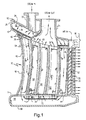
- FIGURE 1 there is schematically illustrated in cross-section a vane 10 comprising one of the plurality of circumferentially arranged segments of the first stage nozzle. It will be appreciated that the segments are connected one to the other to form an annular array of segments defining the hot gas path through the first stage nozzle of the turbine. Each segment includes radially spaced outer and inner walls 12 and 14, respectively, with one or more of the nozzle vanes 10 extending between the outer and inner walls.
- the segments are supported about the inner shell of the turbine (not shown) with adjoining segments being sealed one to the other. It will therefore be appreciated that the outer and inner walls and the vanes extending therebetween are wholly supported by the inner shell of the turbine and are removable with the inner shell halves of the turbine upon removal of the outer shell 16 as set forth in U.S. Patent No. 5,685,693.
- the vane 10 will be described as forming the sole vane of a segment, the vane having a leading edge 18 and a trailing edge 20.
- the first and second stage nozzles i.e., the non-rotating components of the first and second stages, may be removed from the turbine upon removal of the inner shell, as set forth in the above-identified patent, for repair and maintenance and it will also be appreciated that the first and second stage nozzles, having combined closed circuit steam cooling and air cooling may serve as replacement nozzle stages for wholly air cooled nozzle stages whereby the turbine is converted from the solely air cooled turbine to a combined steam and air cooled turbine.
- the first stage nozzle vane segment has a cooling steam inlet 22 to the outer wall 12.
- a return steam outlet 24 also lies in communication with the nozzle segment.
- the outer wall 12 includes outer side railings 26, a leading railing 28, and a trailing railing 30 defining a plenum 32 with the upper surface 34 and an impingement plate 36 disposed in the outer wall 12. (The terms outwardly and inwardly or outer and inner refer to a generally radial direction).
- Disposed between the impingement plate 36 and the inner wall 38 of outer wall 12 are a plurality of structural ribs 40 extending between the side walls 26, forward wall 28 and trailing wall 30.
- the impingement plate 36 overlies the ribs 40 throughout the full extent of the plenum 32. Consequently, steam entering through inlet 22 into plenum 32 passes through the openings in the impingement plate 36 for impingement cooling of the inner surface 38 of the outer wall 12.
- the first stage nozzle vane 10 has a plurality of cavities, for example, the leading edge cavity 42, an aft cavity 44, three intermediate return cavities 46, 48 and 50, and also a trailing edge cavity 52.
- Leading edge cavity 42 and aft cavity 44 each have an insert, 54 and 56 respectively, while each of the intermediate cavities 46, 48 and 50 have similar inserts 58, 60 and 62, respectively, all such inserts being in the general form of hollow, perforated sleeves.
- the inserts may be shaped to correspond to the shape of the particular cavity in which the insert is to be provided.
- the side walls of the sleeves are provided with a plurality of impingement cooling openings, along portions of the insert which lie in opposition to the walls of the cavity to be impingement cooled.
- the forward edge of the insert 54 would be arcuate and the side walls would generally correspond in shape to the side walls of the cavity 42, all such walls of the insert having impingement openings.
- the inserts received in cavities 42, 44, 46, 48, and 50 are spaced from the walls of the cavities to enable cooling media, e.g., steam, to flow through the impingement openings to impact against the interior wall surfaces of the cavities, thus cooling the wall surfaces.
- cooling media e.g., steam
- the post-impingement cooling steam flows into a plenum 66 defined by the inner wall 14 and a lower cover plate 68.
- Structural strengthening ribs 70 are integrally cast with the inner wall 14. Radially inwardly of the ribs 70 is an impingement plate 72.
- Inserts 58, 60 and 62 are disposed in the cavities 46, 48, and 50 in spaced relation from the side walls and ribs defining the respective cavities.
- the impingement openings lie on opposite sides of the sleeves for flowing the cooling media, e.g., steam, from within the inserts through the impingement openings for impingement cooling of the side walls of the vane.
- the spent cooling steam then flows out through outlet 24 for return to, e.g., the steam supply.
- the air cooling circuit of the trailing edge cavity of the combined steam and air cooling circuits of the vane illustrated in FIGURE 1 generally corresponds to that of the '766 patent and, therefore, a detailed discussion herein is omitted.
- FIGURE 2 schematically illustrates exemplary such low LCF regions of the nozzle wall.
- FIGURE 2 schematically illustrates, generally at 73, an exemplary such low LCF region of the nozzle wall.
- One portion of the low LCF region, identified as 75, is of particular interest as this portion of the vane can exhibit a particularly low LCF life.
- Region 75 would be a particularly desirable area in which to reduce the thermal gradient to improve LCF life. However, in some applications it may be desirable to reduce the temperature gradient along a greater part or the entire length of the identified life limiting region 73, or other areas of the nozzle that are generally the same configuration.
- the present invention proposes to modify the typical closed loop steam or air cooled nozzle design by providing for film cooling to greatly reduce local thermal gradient. This in turn increases the local LCF life. More specifically, the invention is embodied in the addition of at least one and preferably a plurality of cooling media, e.g., steam or air, film cooling holes 178 to an otherwise closed loop steam or air cooled nozzle for providing a cooling source for film cooling of the airfoil surface in regions where low LCF life will otherwise exist due to high thermal gradient. Cooling media thus flows out into the hot gas path 176 through film holes 178 defined in the airfoil wall 180 to form a cooing film for cooling the vane exterior.
- cooling media e.g., steam or air
- the film cooling holes are defined in a substantially linear array extending radially along approximately one half the radial length of the airfoil 10, from the radially outer wall 12.
- the illustrated film cooling holes are defined along only a part of the radial length of the airfoil 10, it is to be understood that such a film cooling hole array may extend along a part of the length or along the entire length of its respective vane cavity, as deemed necessary or desirable to effect the cooling to improve LCF life.
- the film cooling hole array is defined in the illustrated embodiment to extend from adjacent the outer wall 12, the film cooling hole array may be defined to extend from the radially inner end of the vane.
- the array of film cooling holes communicating therewith is disposed upstream of the local low LCF region.
- the film cooling holes communicate the leading edge cavity of the airfoil to the exterior.
- an additional array or arrays of film cooling holes may be defined to extend along the leading edge cavity and/or, in addition or in the alternative, one or more such arrays of film cooling holes may be defined in other(s) of the cavities of the airfoil, depending upon the potential low LCF regions and the inevitable cost benefit analysis of the manufacturing complexity and efficiency considerations balanced with the resultant increase in LCF life.
- the film holes 178 are preferably directed rearwardly, i.e. inclined to the plane of the wall 180 of the airfoil 10 so as produce a flow on or along that side wall as a cooling film, so as to cool the local low LCF region disposed in the vicinity and downstream thereof, to reduce the thermal gradient in that region.
Landscapes
- Engineering & Computer Science (AREA)
- Mechanical Engineering (AREA)
- General Engineering & Computer Science (AREA)
- Turbine Rotor Nozzle Sealing (AREA)
Applications Claiming Priority (2)
| Application Number | Priority Date | Filing Date | Title |
|---|---|---|---|
| US09/561,865 US6506013B1 (en) | 2000-04-28 | 2000-04-28 | Film cooling for a closed loop cooled airfoil |
| US561865 | 2000-04-28 |
Publications (2)
| Publication Number | Publication Date |
|---|---|
| EP1149983A2 true EP1149983A2 (de) | 2001-10-31 |
| EP1149983A3 EP1149983A3 (de) | 2003-03-05 |
Family
ID=24243802
Family Applications (1)
| Application Number | Title | Priority Date | Filing Date |
|---|---|---|---|
| EP00311620A Withdrawn EP1149983A3 (de) | 2000-04-28 | 2000-12-22 | Filmkühlung für eine im geschlossenen Kreislauf gekühlte Turbinenschaufel |
Country Status (5)
| Country | Link |
|---|---|
| US (1) | US6506013B1 (de) |
| EP (1) | EP1149983A3 (de) |
| JP (1) | JP2001317302A (de) |
| KR (1) | KR20010098379A (de) |
| CZ (1) | CZ20003682A3 (de) |
Cited By (4)
| Publication number | Priority date | Publication date | Assignee | Title |
|---|---|---|---|---|
| EP1167721A3 (de) * | 2000-06-05 | 2004-06-09 | ALSTOM Technology Ltd | Verfahren zum Kühlen einer Gasturbinenanlage sowie Gasturbinenanlage zur Durchführung des Verfahrens |
| CN102312684A (zh) * | 2011-09-05 | 2012-01-11 | 沈阳黎明航空发动机(集团)有限责任公司 | 一种蒸汽、空气混合冷却透平导向叶片 |
| EP3650655A1 (de) * | 2018-11-09 | 2020-05-13 | United Technologies Corporation | Schaufelprofil, zugehöriges gasturbinentriebwerk und montageverfahren |
| DE102020007518A1 (de) | 2020-12-09 | 2022-06-09 | Svetlana Beck | Verfahren zum Erreichen von hohen Gastemperaturen unter Verwendung von Zentrifugalkraft |
Families Citing this family (32)
| Publication number | Priority date | Publication date | Assignee | Title |
|---|---|---|---|---|
| US6511293B2 (en) * | 2001-05-29 | 2003-01-28 | Siemens Westinghouse Power Corporation | Closed loop steam cooled airfoil |
| US6742984B1 (en) | 2003-05-19 | 2004-06-01 | General Electric Company | Divided insert for steam cooled nozzles and method for supporting and separating divided insert |
| US7086829B2 (en) * | 2004-02-03 | 2006-08-08 | General Electric Company | Film cooling for the trailing edge of a steam cooled nozzle |
| US7303372B2 (en) * | 2005-11-18 | 2007-12-04 | General Electric Company | Methods and apparatus for cooling combustion turbine engine components |
| US7549844B2 (en) * | 2006-08-24 | 2009-06-23 | Siemens Energy, Inc. | Turbine airfoil cooling system with bifurcated and recessed trailing edge exhaust channels |
| US8376706B2 (en) * | 2007-09-28 | 2013-02-19 | General Electric Company | Turbine airfoil concave cooling passage using dual-swirl flow mechanism and method |
| US8079813B2 (en) * | 2009-01-19 | 2011-12-20 | Siemens Energy, Inc. | Turbine blade with multiple trailing edge cooling slots |
| US8052378B2 (en) * | 2009-03-18 | 2011-11-08 | General Electric Company | Film-cooling augmentation device and turbine airfoil incorporating the same |
| US20100239409A1 (en) * | 2009-03-18 | 2010-09-23 | General Electric Company | Method of Using and Reconstructing a Film-Cooling Augmentation Device for a Turbine Airfoil |
| US9039375B2 (en) * | 2009-09-01 | 2015-05-26 | General Electric Company | Non-axisymmetric airfoil platform shaping |
| US9279340B2 (en) | 2010-03-23 | 2016-03-08 | General Electric Company | System and method for cooling gas turbine components |
| US20110232298A1 (en) * | 2010-03-23 | 2011-09-29 | General Electric Company | System and method for cooling gas turbine components |
| US8997498B2 (en) | 2011-10-12 | 2015-04-07 | General Electric Company | System for use in controlling the operation of power generation systems |
| CN103306742B (zh) * | 2012-03-13 | 2015-10-28 | 马重芳 | 冷却燃气轮机叶片的方法 |
| JP2015520322A (ja) | 2012-06-13 | 2015-07-16 | ゼネラル・エレクトリック・カンパニイ | ガスタービンエンジンの壁 |
| US9303518B2 (en) | 2012-07-02 | 2016-04-05 | United Technologies Corporation | Gas turbine engine component having platform cooling channel |
| US9500099B2 (en) | 2012-07-02 | 2016-11-22 | United Techologies Corporation | Cover plate for a component of a gas turbine engine |
| US9222364B2 (en) | 2012-08-15 | 2015-12-29 | United Technologies Corporation | Platform cooling circuit for a gas turbine engine component |
| US20160153282A1 (en) * | 2014-07-11 | 2016-06-02 | United Technologies Corporation | Stress Reduction For Film Cooled Gas Turbine Engine Component |
| US10590785B2 (en) * | 2014-09-09 | 2020-03-17 | United Technologies Corporation | Beveled coverplate |
| WO2016135779A1 (ja) | 2015-02-26 | 2016-09-01 | 株式会社 東芝 | タービン動翼及びタービン |
| US10260356B2 (en) | 2016-06-02 | 2019-04-16 | General Electric Company | Nozzle cooling system for a gas turbine engine |
| US10344619B2 (en) | 2016-07-08 | 2019-07-09 | United Technologies Corporation | Cooling system for a gaspath component of a gas powered turbine |
| US10443397B2 (en) | 2016-08-12 | 2019-10-15 | General Electric Company | Impingement system for an airfoil |
| US10436048B2 (en) | 2016-08-12 | 2019-10-08 | General Electric Comapny | Systems for removing heat from turbine components |
| US10364685B2 (en) | 2016-08-12 | 2019-07-30 | Gneral Electric Company | Impingement system for an airfoil |
| US10408062B2 (en) | 2016-08-12 | 2019-09-10 | General Electric Company | Impingement system for an airfoil |
| JP6353131B1 (ja) * | 2017-06-29 | 2018-07-04 | 三菱日立パワーシステムズ株式会社 | タービン翼及びガスタービン |
| EP3444447A1 (de) * | 2017-08-14 | 2019-02-20 | General Electric Company | Einlassgehäuse für einen gasturbinenmotor |
| EP3444441B1 (de) | 2017-08-14 | 2020-04-08 | General Electric Company | Gasturbinentriebwerk mit einlassgehäuse |
| US10480322B2 (en) * | 2018-01-12 | 2019-11-19 | General Electric Company | Turbine engine with annular cavity |
| US11512597B2 (en) | 2018-11-09 | 2022-11-29 | Raytheon Technologies Corporation | Airfoil with cavity lobe adjacent cooling passage network |
Citations (6)
| Publication number | Priority date | Publication date | Assignee | Title |
|---|---|---|---|---|
| US5253976A (en) | 1991-11-19 | 1993-10-19 | General Electric Company | Integrated steam and air cooling for combined cycle gas turbines |
| US5536143A (en) | 1995-03-31 | 1996-07-16 | General Electric Co. | Closed circuit steam cooled bucket |
| US5593274A (en) | 1995-03-31 | 1997-01-14 | General Electric Co. | Closed or open circuit cooling of turbine rotor components |
| US5611662A (en) | 1995-08-01 | 1997-03-18 | General Electric Co. | Impingement cooling for turbine stator vane trailing edge |
| US5634766A (en) | 1994-08-23 | 1997-06-03 | General Electric Co. | Turbine stator vane segments having combined air and steam cooling circuits |
| US5685693A (en) | 1995-03-31 | 1997-11-11 | General Electric Co. | Removable inner turbine shell with bucket tip clearance control |
Family Cites Families (9)
| Publication number | Priority date | Publication date | Assignee | Title |
|---|---|---|---|---|
| JP3142850B2 (ja) * | 1989-03-13 | 2001-03-07 | 株式会社東芝 | タービンの冷却翼および複合発電プラント |
| US5320483A (en) * | 1992-12-30 | 1994-06-14 | General Electric Company | Steam and air cooling for stator stage of a turbine |
| US5591002A (en) * | 1994-08-23 | 1997-01-07 | General Electric Co. | Closed or open air cooling circuits for nozzle segments with wheelspace purge |
| US5711650A (en) | 1996-10-04 | 1998-01-27 | Pratt & Whitney Canada, Inc. | Gas turbine airfoil cooling |
| US5779437A (en) | 1996-10-31 | 1998-07-14 | Pratt & Whitney Canada Inc. | Cooling passages for airfoil leading edge |
| JP3316405B2 (ja) * | 1997-02-04 | 2002-08-19 | 三菱重工業株式会社 | ガスタービン冷却静翼 |
| JP3238344B2 (ja) * | 1997-02-20 | 2001-12-10 | 三菱重工業株式会社 | ガスタービン静翼 |
| DE59801529D1 (de) * | 1997-04-07 | 2001-10-25 | Siemens Ag | Verfahren zur kühlung einer turbinenschaufel |
| US6261054B1 (en) * | 1999-01-25 | 2001-07-17 | General Electric Company | Coolable airfoil assembly |
-
2000
- 2000-04-28 US US09/561,865 patent/US6506013B1/en not_active Expired - Lifetime
- 2000-10-05 CZ CZ20003682A patent/CZ20003682A3/cs unknown
- 2000-12-22 KR KR1020000080176A patent/KR20010098379A/ko not_active Ceased
- 2000-12-22 EP EP00311620A patent/EP1149983A3/de not_active Withdrawn
- 2000-12-27 JP JP2000396387A patent/JP2001317302A/ja not_active Withdrawn
Patent Citations (6)
| Publication number | Priority date | Publication date | Assignee | Title |
|---|---|---|---|---|
| US5253976A (en) | 1991-11-19 | 1993-10-19 | General Electric Company | Integrated steam and air cooling for combined cycle gas turbines |
| US5634766A (en) | 1994-08-23 | 1997-06-03 | General Electric Co. | Turbine stator vane segments having combined air and steam cooling circuits |
| US5536143A (en) | 1995-03-31 | 1996-07-16 | General Electric Co. | Closed circuit steam cooled bucket |
| US5593274A (en) | 1995-03-31 | 1997-01-14 | General Electric Co. | Closed or open circuit cooling of turbine rotor components |
| US5685693A (en) | 1995-03-31 | 1997-11-11 | General Electric Co. | Removable inner turbine shell with bucket tip clearance control |
| US5611662A (en) | 1995-08-01 | 1997-03-18 | General Electric Co. | Impingement cooling for turbine stator vane trailing edge |
Cited By (8)
| Publication number | Priority date | Publication date | Assignee | Title |
|---|---|---|---|---|
| EP1167721A3 (de) * | 2000-06-05 | 2004-06-09 | ALSTOM Technology Ltd | Verfahren zum Kühlen einer Gasturbinenanlage sowie Gasturbinenanlage zur Durchführung des Verfahrens |
| US7263834B2 (en) | 2000-06-05 | 2007-09-04 | Alstom Technology Ltd | Method for cooling a gas turbine system and a gas turbine system for performing this method |
| CN102312684A (zh) * | 2011-09-05 | 2012-01-11 | 沈阳黎明航空发动机(集团)有限责任公司 | 一种蒸汽、空气混合冷却透平导向叶片 |
| EP3650655A1 (de) * | 2018-11-09 | 2020-05-13 | United Technologies Corporation | Schaufelprofil, zugehöriges gasturbinentriebwerk und montageverfahren |
| US12553348B2 (en) | 2018-11-09 | 2026-02-17 | Rtx Corporation | Airfoil with arced baffle |
| DE102020007518A1 (de) | 2020-12-09 | 2022-06-09 | Svetlana Beck | Verfahren zum Erreichen von hohen Gastemperaturen unter Verwendung von Zentrifugalkraft |
| WO2022122062A1 (de) | 2020-12-09 | 2022-06-16 | Beck, Svetlana | Verfahren zum erreichen von hohen gastemperaturen unter verwendung von zentrifugalkraft |
| CN116547047A (zh) * | 2020-12-09 | 2023-08-04 | S·贝克 | 用于利用离心力获得高气体温度的方法 |
Also Published As
| Publication number | Publication date |
|---|---|
| JP2001317302A (ja) | 2001-11-16 |
| CZ20003682A3 (cs) | 2001-12-12 |
| EP1149983A3 (de) | 2003-03-05 |
| KR20010098379A (ko) | 2001-11-08 |
| US6506013B1 (en) | 2003-01-14 |
Similar Documents
| Publication | Publication Date | Title |
|---|---|---|
| US6506013B1 (en) | Film cooling for a closed loop cooled airfoil | |
| US6435814B1 (en) | Film cooling air pocket in a closed loop cooled airfoil | |
| US6468031B1 (en) | Nozzle cavity impingement/area reduction insert | |
| US5591002A (en) | Closed or open air cooling circuits for nozzle segments with wheelspace purge | |
| US7497655B1 (en) | Turbine airfoil with near-wall impingement and vortex cooling | |
| EP0791127B1 (de) | Gasturbinenschaufel mit einer gekühlten plattform | |
| US6517312B1 (en) | Turbine stator vane segment having internal cooling circuits | |
| US6416275B1 (en) | Recessed impingement insert metering plate for gas turbine nozzles | |
| US5634766A (en) | Turbine stator vane segments having combined air and steam cooling circuits | |
| US5762471A (en) | turbine stator vane segments having leading edge impingement cooling circuits | |
| US6398486B1 (en) | Steam exit flow design for aft cavities of an airfoil | |
| EP1219784B1 (de) | Vorrichtung und Verfahren zur örtlichen Kühlung der Wände von Gasturbinenleitapparaten | |
| US5464322A (en) | Cooling circuit for turbine stator vane trailing edge | |
| JP5898902B2 (ja) | タービン動翼のプラットフォーム区域を冷却するための装置及び方法 | |
| EP1116861A2 (de) | Kreislauf für und Methode zum Kühlen von Gasturbinenschaufeln | |
| EP1052374B1 (de) | Kühlkreislauf für dampf- und luftgekühlte Turbinenleitschaufeln | |
| CA2456628A1 (en) | Microcircuit cooling for a turbine blade tip | |
| CA2205042C (en) | Gas turbine vane with a cooled inner shroud | |
| CA2258206C (en) | Configuration of cooling channels for cooling the trailing edge of gas turbine vanes |
Legal Events
| Date | Code | Title | Description |
|---|---|---|---|
| PUAI | Public reference made under article 153(3) epc to a published international application that has entered the european phase |
Free format text: ORIGINAL CODE: 0009012 |
|
| AK | Designated contracting states |
Kind code of ref document: A2 Designated state(s): AT BE CH CY DE DK ES FI FR GB GR IE IT LI LU MC NL PT SE TR |
|
| AX | Request for extension of the european patent |
Free format text: AL;LT;LV;MK;RO;SI |
|
| PUAL | Search report despatched |
Free format text: ORIGINAL CODE: 0009013 |
|
| AK | Designated contracting states |
Kind code of ref document: A3 Designated state(s): AT BE CH CY DE DK ES FI FR GB GR IE IT LI LU MC NL PT SE TR Designated state(s): AT BE CH CY DE DK ES FI FR GB GR IE IT LI LU MC NL PT SE TR |
|
| AX | Request for extension of the european patent |
Extension state: AL LT LV MK RO SI |
|
| RIC1 | Information provided on ipc code assigned before grant |
Ipc: 7F 01D 25/12 B Ipc: 7F 01D 5/18 A |
|
| 17P | Request for examination filed |
Effective date: 20030905 |
|
| AKX | Designation fees paid |
Designated state(s): AT BE CH CY DE DK ES FI FR GB GR IE IT LI LU MC NL PT SE TR |
|
| 17Q | First examination report despatched |
Effective date: 20040303 |
|
| STAA | Information on the status of an ep patent application or granted ep patent |
Free format text: STATUS: THE APPLICATION IS DEEMED TO BE WITHDRAWN |
|
| 18D | Application deemed to be withdrawn |
Effective date: 20040701 |