EP1149789A2 - Web conveying apparatus, and apparatus and method for electrodeposition using web conveying apparatus - Google Patents
Web conveying apparatus, and apparatus and method for electrodeposition using web conveying apparatus Download PDFInfo
- Publication number
- EP1149789A2 EP1149789A2 EP01107585A EP01107585A EP1149789A2 EP 1149789 A2 EP1149789 A2 EP 1149789A2 EP 01107585 A EP01107585 A EP 01107585A EP 01107585 A EP01107585 A EP 01107585A EP 1149789 A2 EP1149789 A2 EP 1149789A2
- Authority
- EP
- European Patent Office
- Prior art keywords
- web
- electrodeposition
- roller
- vessel
- axis
- Prior art date
- Legal status (The legal status is an assumption and is not a legal conclusion. Google has not performed a legal analysis and makes no representation as to the accuracy of the status listed.)
- Withdrawn
Links
Images




Classifications
-
- B—PERFORMING OPERATIONS; TRANSPORTING
- B65—CONVEYING; PACKING; STORING; HANDLING THIN OR FILAMENTARY MATERIAL
- B65H—HANDLING THIN OR FILAMENTARY MATERIAL, e.g. SHEETS, WEBS, CABLES
- B65H23/00—Registering, tensioning, smoothing or guiding webs
- B65H23/04—Registering, tensioning, smoothing or guiding webs longitudinally
- B65H23/06—Registering, tensioning, smoothing or guiding webs longitudinally by retarding devices, e.g. acting on web-roll spindle
- B65H23/10—Registering, tensioning, smoothing or guiding webs longitudinally by retarding devices, e.g. acting on web-roll spindle acting on running web
- B65H23/105—Registering, tensioning, smoothing or guiding webs longitudinally by retarding devices, e.g. acting on web-roll spindle acting on running web and controlling web tension
-
- B—PERFORMING OPERATIONS; TRANSPORTING
- B21—MECHANICAL METAL-WORKING WITHOUT ESSENTIALLY REMOVING MATERIAL; PUNCHING METAL
- B21C—MANUFACTURE OF METAL SHEETS, WIRE, RODS, TUBES, PROFILES OR LIKE SEMI-MANUFACTURED PRODUCTS OTHERWISE THAN BY ROLLING; AUXILIARY OPERATIONS USED IN CONNECTION WITH METAL-WORKING WITHOUT ESSENTIALLY REMOVING MATERIAL
- B21C47/00—Winding-up, coiling or winding-off metal wire, metal band or other flexible metal material characterised by features relevant to metal processing only
- B21C47/003—Regulation of tension or speed; Braking
-
- B—PERFORMING OPERATIONS; TRANSPORTING
- B21—MECHANICAL METAL-WORKING WITHOUT ESSENTIALLY REMOVING MATERIAL; PUNCHING METAL
- B21C—MANUFACTURE OF METAL SHEETS, WIRE, RODS, TUBES, PROFILES OR LIKE SEMI-MANUFACTURED PRODUCTS OTHERWISE THAN BY ROLLING; AUXILIARY OPERATIONS USED IN CONNECTION WITH METAL-WORKING WITHOUT ESSENTIALLY REMOVING MATERIAL
- B21C47/00—Winding-up, coiling or winding-off metal wire, metal band or other flexible metal material characterised by features relevant to metal processing only
- B21C47/34—Feeding or guiding devices not specially adapted to a particular type of apparatus
-
- B—PERFORMING OPERATIONS; TRANSPORTING
- B21—MECHANICAL METAL-WORKING WITHOUT ESSENTIALLY REMOVING MATERIAL; PUNCHING METAL
- B21C—MANUFACTURE OF METAL SHEETS, WIRE, RODS, TUBES, PROFILES OR LIKE SEMI-MANUFACTURED PRODUCTS OTHERWISE THAN BY ROLLING; AUXILIARY OPERATIONS USED IN CONNECTION WITH METAL-WORKING WITHOUT ESSENTIALLY REMOVING MATERIAL
- B21C47/00—Winding-up, coiling or winding-off metal wire, metal band or other flexible metal material characterised by features relevant to metal processing only
- B21C47/34—Feeding or guiding devices not specially adapted to a particular type of apparatus
- B21C47/3408—Feeding or guiding devices not specially adapted to a particular type of apparatus for monitoring the lateral position of the material
- B21C47/3425—Feeding or guiding devices not specially adapted to a particular type of apparatus for monitoring the lateral position of the material without lateral edge contact
-
- B—PERFORMING OPERATIONS; TRANSPORTING
- B21—MECHANICAL METAL-WORKING WITHOUT ESSENTIALLY REMOVING MATERIAL; PUNCHING METAL
- B21C—MANUFACTURE OF METAL SHEETS, WIRE, RODS, TUBES, PROFILES OR LIKE SEMI-MANUFACTURED PRODUCTS OTHERWISE THAN BY ROLLING; AUXILIARY OPERATIONS USED IN CONNECTION WITH METAL-WORKING WITHOUT ESSENTIALLY REMOVING MATERIAL
- B21C47/00—Winding-up, coiling or winding-off metal wire, metal band or other flexible metal material characterised by features relevant to metal processing only
- B21C47/34—Feeding or guiding devices not specially adapted to a particular type of apparatus
- B21C47/345—Feeding or guiding devices not specially adapted to a particular type of apparatus for monitoring the tension or advance of the material
-
- B—PERFORMING OPERATIONS; TRANSPORTING
- B65—CONVEYING; PACKING; STORING; HANDLING THIN OR FILAMENTARY MATERIAL
- B65H—HANDLING THIN OR FILAMENTARY MATERIAL, e.g. SHEETS, WEBS, CABLES
- B65H23/00—Registering, tensioning, smoothing or guiding webs
- B65H23/02—Registering, tensioning, smoothing or guiding webs transversely
- B65H23/032—Controlling transverse register of web
- B65H23/038—Controlling transverse register of web by rollers
-
- B—PERFORMING OPERATIONS; TRANSPORTING
- B21—MECHANICAL METAL-WORKING WITHOUT ESSENTIALLY REMOVING MATERIAL; PUNCHING METAL
- B21B—ROLLING OF METAL
- B21B37/00—Control devices or methods specially adapted for metal-rolling mills or the work produced thereby
- B21B37/68—Camber or steering control for strip, sheets or plates, e.g. preventing meandering
-
- B—PERFORMING OPERATIONS; TRANSPORTING
- B65—CONVEYING; PACKING; STORING; HANDLING THIN OR FILAMENTARY MATERIAL
- B65H—HANDLING THIN OR FILAMENTARY MATERIAL, e.g. SHEETS, WEBS, CABLES
- B65H2511/00—Dimensions; Position; Numbers; Identification; Occurrences
- B65H2511/20—Location in space
- B65H2511/21—Angle
- B65H2511/214—Inclination
-
- B—PERFORMING OPERATIONS; TRANSPORTING
- B65—CONVEYING; PACKING; STORING; HANDLING THIN OR FILAMENTARY MATERIAL
- B65H—HANDLING THIN OR FILAMENTARY MATERIAL, e.g. SHEETS, WEBS, CABLES
- B65H2555/00—Actuating means
- B65H2555/20—Actuating means angular
- B65H2555/24—Servomotors
Definitions
- the present invention relates to a conveying apparatus for conveying a web (a elongated substrate) used as elements or parts with functional film formed thereon, which is wound up in coil form and handled in the apparatus.
- the present invention specifically relates to a web conveying apparatus wherein when a web in coil form is unwound for film deposition and then rewound up in coil form, expansion or wrinkle does not occur at the web edges and the web is conveyed along its predetermined path without strain then wound up in coil form with edge alignment.
- the present invention also relates to a electrodeposition apparatus and a electrodeposition method using such a web conveying apparatus.
- deviation of a web is detected by using a optical-based, light-blocking edge detector, and the output signal is fed back to a servomotor, and output of the servomotor is transmitted through a link mechanism to a wheel gear that is provided on one end face of a roller with being eccentric to the axis of the roller, so that the axis of the roller is tilted and tension applied to the web at one side of the roller is varied with respect to tension at the other side of the roller, so as to axially move the web.
- Japanese Patent Application Laid-Open No. 5-270710 discloses a mechanism wherein web meandering is corrected by varying the direction of a guide roll (the term “roller” in the invention has same meaning as "roll(s)” mentioned in above example for conventional art, and so forth.), or axially moving the roll.
- this invention intends to combine varying direction of the guide role and axially moving the roll, which effects easily coarse meandering correction but does not effect easily fine meandering correction, since when the amount of meandering is large, if direction of the guide roll is only changed, wrinkles may occur and meandering correction may not be possible.
- Japanese Patent Application Laid-Open No. 6-239508 discloses a meandering correction mechanism wherein fixed roles and displacement rolls are combined. This invention intends that when correcting web meandering on the displacement rolls that turn back a web between fixed rolls, relative positioning between the displacement rolls are implemented by a press-contact force regulation mechanism.
- Japanese Patent Application Laid-Open No. 10-296317 (a metal strip conveying apparatus, made open to public by Nippon Steel on November 10, 1998) describes a method to prevent zigzag movement with combination of a free loop, a pinch roller and a crown roll.
- Japanese Patent Application Laid-Open No. 8-197124 (a method to control zigzag movement of metal plates) discloses a system to form a catenary and judge zigzag amounts from difference in catenary level at the both ends so as to adjust the zigzag by tilting an axis of a roll. Forming catenaries positively is adopted often in order to adjust velocity in case of conveying metal plates and the like.
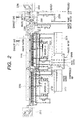
- Fig. 2 A general configuration as well as operation of the actually produced electrodeposition apparatus is shown in Fig. 2. Moreover, divided and enlarged views thereof are shown in Fig. 3 to Fig. 9. Fig. 2 as well as Fig. 3 to Fig. 9 shares common names and reference numerals for respective portions.
- the apparatus roughly breaks down to a wind-off apparatus 2012 to deliver a coiled web, a first electrodeposition vessel 2066 to cause the first electrodeposited film to be processed or deposited, a second electrodeposition vessel 2116 to cause the second electrodeposited film to be deposited or processed, a first circulating vessel 2120 to circulate-supply a heated electrodeposition bath to the first electrodeposition vessel, a second circulating vessel 2222 to circulate-supply a heated electrodeposition bath to the second electrodeposition vessel, a fist discharging vessel 2172 to temporarily store the bath when to discharge the electrodeposition bath in the first electrodeposition vessel, a second discharging vessel 2274 to temporarily store the bath when to discharge the electrodeposition bath in the second electrodeposition vessel, a filter circulation system to clean the bath by removing powder in the electrodeposition bath inside the first electrodeposition vessel (a pipe system linked to the first electrodeposition vessel filter circulation filter 2161), a filter circulation system to clean the bath by removing powder in the electrodeposition bath inside the second electrodeposition vessel (a pipe system linked to the second electrodeposition vessel
- the web is conveyed sequentially from left to right in the drawings via the wind-off apparatus 2012, the first electrodeposition vessel 2066, the second electrodeposition vessel 2116, the pure water shower vessel 2360, the first warm water vessel 2361, the second warm water vessel 2362, the dryer section 2363 and wind-up apparatus 2296 so that a predetermined electrodeposited film is deposited.
- a coiled web 2006 which is coiled around the wind-off apparatus web bobbin 2001 is set in the wind-off apparatus 2012, which goes on delivering the web 2006 via the wind-off apparatus delivery control roller 2003, the wind-off apparatus direction change roller 2004 and the wind-off apparatus discharging roller 2005.
- the coiled web is supplied with an interleaf (slipsheet) being sandwiched to protect a substrate or a layer in the case where an underlining layer is deposited in advance in particular. Therefore, in the case where the interleaf is coiled in, along with wind-off of the web the interleaf 2007 is wound up by a wind-off apparatus interleaf wind-up bobbin 2002.
- the conveying direction of the web 2006 is indicted by an arrow 2010, the rotating direction of the wind-up apparatus web bobbin 2010 is indicated by an arrow 2009, and the wind-up direction of the wind-off apparatus interleaf wind-up bobbin 2002 is indicated by an arrow 2008.
- the web discharged from the wind-off apparatus web bobbin 2001 and the interleaf wound up by the wind-off apparatus interleaf wind-up bobbin 2002 respectively indicates that interference has not taken place at a position at the time when conveyance starts and at a position at the time when conveyance ends.
- the wind-off apparatus in its entirety is configured so as to be covered by the wind-off apparatus clean booth 2011 using a HEPA filter and a down flow for protection against dust.
- the first electrodeposition vessel 2066 is, as shown in Fig. 4, held in the first electrodeposition bath holding vessel 2065 that can keep the electrodeposition bath warm without being corrosive to the electrodeposition bath so that the temperature controlled electrodeposition bath will be the first electrodeposition bath bath surface 2025.
- the position of this bath surface is realized with over flow by the partition provided inside the first electrodeposition bath holding vessel 2065.
- the not-shown partition is installed so as to drop the electrodeposition bath toward the depth of the first electrodeposition bath holding vessel 2065, and the overflow electrodeposition bath focused to the first electrodeposition vessel overflow return orifice 2024 with a bucket structure reaches the first circulating vessel 2120 via the first electrodeposition vessel overflow return path 2117, and is heated here to flow back again from the first electrodeposition upstream circulation nozzle tube 2063 and the first electrodeposition downstream circulation nozzle tube 2064 to the first electrodeposition bath holding vessel 2065 so as to form inflow of the electrodeposition bath sufficient to urge an overflow.
- the web 2006 passes inside the first electrodeposition vessel 2066 via a electrodeposition vessel entrance return roller 2013, a first electrodeposition vessel approach roller 2014, a first electrodeposition vessel withdraw roller 2015, and an inter-electrodeposition return roller 2016.
- a first electrodeposition vessel approach roller 2014 and the first electrodeposition withdraw roller 2015 at least the lower side face of the web being a filmed surface (to be referred to as "front face" in the present specification) is in the electrodeposition bath, opposing 28 units of anodes 2026 to 2053.
- the actual electrodeposition is executed by giving a negative potential to the web and a positive potential to the anode and by causing an electrodeposition current accompanied by electrochemical reaction to flow between the both parties in the electrodeposition bath.
- the anode in the first electrodeposition vessel comprises four units each are mounted on seven anode mounting stands 2054 to 2060 (See Fig. 4).
- An anode mounting stand is structured so that the respective anodes are put via insulating plates and individual potentials are applied from an independent power supply.
- the anode mounting stands 2054 to 2060 are assigned to function to hold gaps between the web and the anodes 2026 to 2053 in the electrodeposition bath. Therefore, normally, the anode amounting stands 2054 to 2060 are designed and produced so as to be capable of adjusting height to hold a predetermined gap.
- a first electrodeposition vessel rear surface electrode 2061 provided to immediately precede the first electrodeposition vessel withdraw roller 2015 is the one to remove electrochemically the film deposited on the opposite face against the filmed surface of the web (to be referred to as "rear face" in the present specification), and this is realized by taking the first electrodeposition vessel rear face electrode 2061 as the negative side potential against the web.
- the fact that the first electrodeposition rear face electrode 2061 is actually effective is confirmed in that a film, which is attached electrochemically onto the rear face in the opposite side of the filmed surface of the web by a wraparound electric field, having the same quality as that of the film formed on the filmed surface of the web, is rapidly removed under visual observation.
- the electrodeposition bath is applied from the first electrodeposition vessel exit shower 2067 so as to prevent the filmed surface from being dried and giving rise to surface irregularity.
- an inter-electrodeposition cover 2019 provided in the bridge portion between the first electrodeposition vessel 2066 and the second electrodeposition vessel 2116 also shuts the steam generated from the electrodeposition vessel and prevent the filmed surface of the web from being dried.
- a second electrodeposition vessel entrance shower 2068 functions to prevent from being dried as well.
- the first circulating vessel 2120 is in charge of heating and keeping warm the electrodeposition bath and jet circulation thereof inside the first electrodeposition vessel 2066.
- the electrodeposition bath having overflowed in the first electrodeposition vessel 2066 is collected into the first electrodeposition vessel overflow return orifice 2024, passes the first electrodeposition vessel overflow return path 2117, and reaches the first circulation vessel heat storage vessel 2121 via the first electrodeposition vessel overflow return path insulating flange 2118.
- the first circulation vessel heaters 2122 to 2129 are provided, and these functions at the time when an electrodeposition bath under room temperature is initially heated or at the time when the electrodeposition bath losing its bath temperature due to circulation is heated again to hold the electrodeposition bath at a predetermined temperature.
- Two circulation systems are connected with the first circulation vessel heat storage vessel 2121. That is, one is the first electrodeposition vessel upstream circulation return current system to return from the first electrodeposition vessel upstream circulation nozzle tube 2063 to the first electrodeposition bath holding vessel 2065 via a first circulation vessel electrodeposition bath upstream circulation origin valve 2130, a first circulation vessel electrodeposition bath upstream circulation pump 2132, a first circulation vessel electrodeposition bath upstream circulation valve 2135, a first circulation vessel electrodeposition bath upstream circulation flexible pipe 2136 and a first circulation vessel electrodeposition bath upstream circulation flange insulation pipe 2137 and the other is the first electrodeposition vessel downstream circulation return current system to return from the first electrodeposition vessel downstream circulation nozzle tube 2064 to the first electrodeposition bath holding vessel 2065 via a first circulation vessel electrodeposition bath downstream circulation origin valve 2139, a first circulation vessel electrodeposition bath downstream circulation pump 2142, a first circulation vessel electrodeposition bath downstream circulation valve 2145, a first circulation vessel electrodeposition bath downstream circulation flexible valve 2148 and a first circulation vessel electrodeposition bath downstream circulation flange insulation pipe 2149
- the electrodeposition bath returning from the first electrodeposition vessel upstream circulation nozzle tube 2063 and the first electrodeposition vessel downstream circulation nozzle tube 2064 to the first electrodeposition vessel 2066 is caused to flow back as a jet stream from the first electrodeposition vessel upstream circulation nozzle tube 2063 provided in the lower portion of the first electrodeposition bath holding vessel 2065 and the first electrodeposition vessel downstream circulation nozzle tube 2064 via orifices respectively created by piercing the nozzle tubes so as to effectuate the electrodeposition bath exchange inside the first electrodeposition bath holding vessel 2065.
- the return amounts in the respective circulation return current systems are controlled by a closing level of the first circulation vessel electrodeposition bath upstream circulation valve 2135 or the first circulation vessel electrodeposition bath downstream circulation valve 2145, and further delicate adjustment is controlled by a first circulation vessel electrodeposition bath upstream circulation pump bypass valve 2133 or a first circulation vessel electrodeposition bath downstream circulation pump bypass valve 2141 provided in a bypass system which has been brought into connection by short-circuiting the exit and the entrance of the first circulation vessel electrodeposition bath upstream circulation pump 2132 or the first circulation vessel electrodeposition bath downstream circulation pump 2142.
- the bypass systems function to prevent cavitation from taking place inside the pumps in the case where the return current amount is made less or at the time when the bath temperature is extremely close to the boiling point. Cavitation under which the bath fluid is boiled and evaporated so that a liquid is no longer deliverable will remarkably shorten the life of the pumps.
- the return current amount is almost determined by the pressure to bring back the bath fluid to the first circulation vessel electrodeposition bath upstream circulation nozzle tube 2063 and the first circulation vessel electrodeposition bath downstream circulation nozzle tube 2064.
- a first circulation vessel electrodeposition bath upstream circulation pressure gage 2134 and a first circulation vessel electrodeposition bath downstream circulation pressure gage 2143 are provided so that the balance in the return current amounts can be known with these pressure gages.
- the return current bath fluid amount discharged from the orifices exactly follow the Verneuil's theorem, but with orifices pierced in the nozzle tubes having a diameter of not more than several millimeters the jet stream amount all over the first electrodeposition vessel upstream circulation nozzle tube 2063 to the first electrodeposition vessel downstream circulation nozzle tube 2064 can be treated as a constant in a practical term.
- the bath can be exchanged extremely smoothly so that in spite of rather long first electrodeposition vessel 2066 uniformity of the bath density as well as uniformity of the temperature thereof can be planned effectively. It goes without saying that the first electrodeposition vessel overflow return path 2117 should have this thickness cable of flowing a sufficient return current amount.
- the first circulation vessel electrodeposition bath upstream circulation flexible pipe 2136 and the first circulation vessel electrodeposition bath downstream circulation flexible pipe 2148 provided in the respective circulation return current systems are to absorb deformation in pipe systems, and in particular are effective in the case where flange insulation pipes, etc. which are apt to suffer from shortage of mechanical intensiveness against deformation.
- the first circulation vessel electrodeposition bath upstream circulation flange insulation pipe 2137 and the first circulation vessel electrodeposition bath downstream circulation flange insulation pipe 2149 provided in the respective circulation return current systems cause the first circulation vessel 2120 and the first electrodeposition vessel 2066 to float electrically together with the first electrodeposition vessel overflow return path insulation flange 2118 provided in midway of the first electrodeposition vessel overflow return path 2117. This is based on knowledge of the present inventors that giving up formation of unnecessary current route, that is, prevention of stray currents leads to steady and effective progress of electrochemical filming reaction utilizing electrodeposition currents.
- the other circulation return current system is provided with a bypass return current system configured by a first circulation vessel electrodeposition bath bypass circulation flexible pipe 2146 and a first circulation vessel electrodeposition bath bypass circulation flexible valve 2147 to return to a first circulation vessel heat storage vessel 2121 directly, and this is to be used in the case where bath circulation is desired to be executed without the bath fluid is returned to the first electrodeposition vessel, for example, at the time when temperature rises from room temperature to predetermined temperature and the like.
- one circulation return current system from the first circulation vessel is provided with a fluid delivery system reaching to the first electrodeposition exit shower 2067 to apply the electrodeposition bath to the web which has passed the first electrodeposition vessel withdraw roller 2015 and come out from the electrodeposition bath, which leads to the first electrodeposition exit shower 2067 via the first electrodeposition exit shower valve 2150.
- An electrodeposition liquid spray amount from the first electrodeposition exit shower 2067 is adjusted by adjusting the closing level of the first electrodeposition exit shower valve 2150.
- the first circulation vessel heat storage vessel 2121 is provided with a cover so as to be structured to prevent water from becoming steam and going away.
- the temperature of the cover will rise, and therefore consideration of sticking an insulating material and the like is necessary from the point of view of safety.
- a filter circulation system For removing powder of the first electrodeposition vessel electrodeposition bath, a filter circulation system is provided.
- the filter circulation system for the first electrodeposition vessel is configured by a first electrodeposition vessel filter circulation return flexible pipe 2151, a first electrodeposition vessel filter circulation return flange insulation pipe 2152, a first electrodeposition vessel filter circulation origin valve 2154, a first electrodeposition vessel filter circulation suction filter 2156, a first electrodeposition vessel filter circulation pump 2157, a first electrodeposition vessel filter circulation pump bypass valve 2158, a first electrodeposition vessel filter circulation pressure switch 2159, a first electrodeposition vessel filter circulation pressure gage 2160, a first electrodeposition vessel filter circulation filter 2161, a first electrodeposition vessel filter circulation flexible pipe 2164, a first electrodeposition vessel filter circulation flange insulation pipe 2165, a first electrodeposition vessel filter circulation valve 2166, a first electrodeposition vessel filter circulation system electrodeposition bath upstream return valve 2167, a first electrodeposition vessel filter circulation system electrodeposition midstream return valve 2168 and a first electrodeposition vessel filter circulation system electrodeposition
- the electrodeposition bath will flow in the direction of the first electrodeposition vessel filter circulation direction 2155, ditto 2162 and ditto 2163.
- the powder to be removed could be plunged in from outside the machine, or could be formed on the electrode surface or in the bath corresponding with the electrodeposition reaction.
- the minimum size of the powder to be removed is determined by the filter size of the first electrodeposition vessel filter circulation filter 2161.
- the first electrodeposition vessel filter circulation return flexible pipe 2151 and the first electrodeposition vessel filter circulation flexible pipe 2164 absorb deformation of pipes to minimize leakage of liquid from pipe connecting portions, to protect insulation pipes which are inferior in mechanical intensity and to freedom in disposition of components of the circulation system including pumps.
- the purpose of the first electrodeposition vessel filter circulation return flange insulation pipe 2152 as well as the first electrodeposition vessel filter circulation flange insulation pipe 2165 is to cause the first electrodeposition bath holding vessel 2065 which is floating above the ground earth to float in order to prevent it from dropping onto the ground earth.
- the first electrodeposition vessel filter circulation suction filter 2156 which is a metal mesh or, so to speak, a "tea strainer", removes a large dusts so as to protect succeeding first electrodeposition vessel filter circulation pump 2157 or the first electrodeposition vessel filter circulation filter 2161.
- the first electrodeposition vessel filter circulation filter 2161 which plays the main role in this circulation system, is to remove powder mixed in or generated in the electrodeposition bath.
- the circulation current amount of the electrodeposition bath of the present circulation system is minutely adjusted mainly with the first electrodeposition vessel filter circulation valve 2166 and subsequently with the first electrodeposition vessel filter circulation pump bypass valve 2158 provided in parallel along the first electrodeposition vessel filter circulation pump 2157.
- the first electrodeposition vessel filter circulation pressure gage 2160 is provided. Besides the minute adjustment of the current amount, the first electrodeposition vessel filter circulation pump bypass valve 2158 prevents cavitation from taking place at the time when the filter circulation current amount in its entirety is tightened and damaging the first electrodeposition vessel filter circulation pump 2157.
- the electrodeposition bath can be transferred from a first electrodeposition vessel draining valve 2153 to the fist discharging vessel 2172 via the first electrodeposition vessel filter circulation return flange insulation pipe 2152. This transfer is executed at the time of electrodeposition bath exchange, maintenance of the apparatus or emergency.
- the electrodeposition bath as the transferred waste fluid is caused to drop into the first waste fluid vessel waste fluid storage vessel 2144 by way of gravitational drop.
- the first waste fluid vessel waste fluid storage vessel 2144 preferably has a capacity that can store to fulfill at least the total of the bath capacity of the first electrodeposition vessel 2066 and the first circuit vessel 2120.
- the first waste fluid vessel waster fluid storage vessel upper cap 2277 is installed in the first waste fluid vessel waste fluid storage vessel 2144, and in order to effectuate gravitational dropping transfer of the electrodeposition bath, a first waste fluid vessel air-bleeder 2171 as well as a first waste fluid vessel air vent valve 2170 is provided.
- the electrodeposition bath temporarily having dropped into the first waste fluid vessel waste fluid storage vessel 2144 loses temperature, and thereafter is brought into waste water treatment at the building side from the first waste fluid vessel waste water valve 2173, or is collected into a now shown drum can via a first waste liquid vessel waste fluid collection valve 2174, a waster fluid collection origin valve 2175, a waste fluid collection suction filter 2176 and a waste liquid collection pump 2177 so as to be properly disposed.
- dilution with water and treatment by way of a chemical liquid, etc. are executed inside the first waste fluid vessel waste fluid storage vessel 2144.
- air bubbles are arranged to be gushed out from a plurality of orifices pierced in the first electrodeposition vessel stirring air introducing tube 2062 installed in the bottom portion of the first electrodeposition bath holding vessel 2065.
- the air which is compressed air supplied to a factor, is taken in from the compressed air introducing orifice 2182, and reaches the first electrodeposition vessel stirring air introducing tube 2062 via an electrodeposition bath stirring compressed air pressure switch 2183, sequentially passing in the direction indicated to the first electrodeposition vessel compressed air introducing direction 2184, a first electrodeposition vessel compressed air origin valve 2185, a first electrodeposition vessel compressed air current amount meter 2186, a first electrodeposition vessel compressed air regulator 2187, a first electrodeposition vessel compressed air mist separator 2188, a first electrodeposition vessel compressed air introducing valve 2189, a first electrodeposition vessel compressed air flexible pipe 2190, a first electrodeposition vessel compressed air insulation pipe 2191, and a first electrodeposition vessel compressed air upstream side control valve 2193 or a first electrodeposition vessel compressed air downstream side control valve 2192.
- the web conveyed to the second electrodeposition vessel 2116 via the inter-electrodeposition return roller 2016 undergoes deposition of a second electrodeposited film or treatment.
- the second electrodeposited film may be the same as the first electrodeposited film to form one film with the first electrodeposited film and the second electrodeposited film, in addition, in spite of adopting the same quality, may be two-layer lamination provided with different characteristics (for example, lamination of layers different in particle size for zinc oxide), or in spite of adopting the same characteristics, may be two-layer lamination provided with different quality (for example, lamination of indium oxide as a transparent electroconductive film and zinc oxide), or may be a lamination of completely different two layers, and moreover, low oxide is deposited in the first electrodeposition vessel 2066 while treatment to proceed with oxidation in the second electrodeposition vessel 2116 is executed, or oxide is deposited in the first electrodeposition vessel 2066 while corrosive carving treatment in the second electrodeposition 2116 is executed.
- conditions on electrodeposition or treatment such as electrodeposition bath or treatment bath, bath temperature, bath circulation amount, electric current density and stirring amount and the like are selected to comply with respective objects.
- time of electrodeposition or treatment for the first electrodeposition vessel 2066 needs to be different from those for the second electrodeposition vessel 2116, change in the conveyance time of the web 2006 to be different from that for the second electrodeposition 2116 will do, for the purpose thereof, change in length of vessel for the first electrodeposition vessel 2066 to be different from that for the second electrodeposition vessel 2166 is done, or the web is returned for adjustment.
- the second electrodeposition vessel 2116 is held as shown in Fig. 5 in the second electrodeposition bath holding vessel 2115 that can keep the electrodeposition bath warm without corrosion against the electrodeposition bath so that the temperature controlled electrodeposition bath will become the second electrodeposition bath bath surface 2025.
- the position of this bath surface is realized by overflow by way of a partition provided inside the second electrodeposition bath holding vessel 2115.
- the not shown partition is installed so as to drop the electrodeposition bath to the direction of depth in the second electrodeposition bath holding vessel 2115 in its entirety, and the overflowed electrodeposition bath collected into the second electrodeposition vessel overflow return orifice 2075 with a gutter structure reaches the second circulation vessel 2222 via the second electrodeposition vessel overflow return path 2219, and here is heated so as to be returned again to the second electrodeposition bath holding vessel 2115 from the second electrodeposition vessel upstream circulation nozzle tube 2113 as well as the second electrodeposition vessel downstream circulation nozzle tube 2114 to form inflow of electrodeposition bath sufficient to urge overflow.
- the web 2006 passes through an electrodeposition inter-vessel shuttle roller 2016, a second electrodeposition vessel entry roller 2069, a second electrodeposition vessel withdrawal roller 2070 and a pure water shower vessel shuttle entry roller 2279 into the second electrodeposition vessel 2116. Between the second electrodeposition vessel entry roller 2069 and the second electrodeposition vessel withdrawal roller 2070, the web surface is present in electrodeposition bath and faces 28 second electrodeposition vessel anodes 2076 to 2103.
- the actual electrodeposition is carried out by giving negative and positive potentials to the web and the anodes, respectively, to let an electrodeposition current entailing an electrochemical reaction flow between them in the electrodeposition bath.
- anodes in the second electro-deposition vessel are placed on seven second electrodeposition vessel anode placement stand 2104 to 2110 four for each (See Fig. 5).
- Each anode placement stand is so structured as to take its respective anodes on it via an insulating plate and is so arranged that a peculiar potential is applied to it from an independent power supply.
- the anode placement stands 2104 to 2110 also function to keep an interval between the web and the anodes 2076 to 2103 in the electrodeposition bath.
- the anode placement stands 2104 to 2110 are so designed and fabricated as capable of height adjustment.
- the second electrodeposition vessel back face electrode 2111 provided in direct front of the second electrodeposition vessel exit roller 2070 serves to electrochemically remove the film deposited on the back face of the web in the vessel, which purpose is implemented by setting the second electrodeposition vessel electrode 2111 to a negative electrode relative to the web as with the first electrodeposition vessel electrode 2061.
- the electrodeposition bath is applied from the electrodeposition vessel outlet shower 2297 and prevents the unevenness from occurring due to the drying of the formed film surface.
- a pure water shower vessel shuttle entry roller cover 2318 which is provided at a connecting portion between the second electrodeposition vessel 2116 and the pure water shower vessel 2360, confines the vapor generated from the electrodeposition bath to prevent the formed film surface of the web from being dried.
- a pure water shower vessel inlet surface pure water shower 2299 and a pure water vessel inlet back face pure water shower 2300 also perform a similar action in addition to washing away the electrodeposition bath.
- the second circulation vessel 2222 bears the heating or keeping warmth and current circulation of the electrodeposition bath in the second electrodeposition vessel 2116.
- the electrodeposition bath overflown in the second electro-deposition vessel 2116 is collected to a second electrodeposition vessel overflow return port 2075, goes along a second electrodeposition vessel overflow return path 2219, passes through a second electrodeposition vessel overflow return path insulating flange 2220 and arrives at a second circulation vessel heating tank 2223.
- eight second circulation vessel heaters 2224 to 2234 are provided and are made to function in initially heating an electrodeposition at room temperatures or in reheating an electrodeposition bath with a decrease in temperature by the circulation to retain the electro-deposition bath to a predetermined temperature.
- two circulation systems are connected.
- they are a second electrodeposition vessel upstream circulatory reflux system returning from the second electrodeposition vessel upstream circulation jet tube 2113 to the second electro- deposition bath retention vessel 2115 via a second circulation vessel electrodeposition bath upstream circulation source valve 2232, a second circulation vessel electrodeposition bath upstream circulation pump 2234, a second circulation vessel electro-deposition bath upstream circulation valve 2237, a second circulation vessel electrodeposition bath upstream circulation flexible pipe 2238 and a second circulation vessel electro-deposition bath upstream circulation flange insulating piping 2239 and a second electrodeposition vessel downstream circulation reflex system returning from the second electro-deposition vessel downstream circulation jet tube 2114 to the second electrodeposition bath retention vessel 2115 via a second circulation vessel electrodeposition bath downstream circulation source valve 2242, a second circulation vessel electrodeposition bath downstream circulation pump 2245, second circulation vessel electrodeposition bath downstream circulation valve 2247, a second circulation vessel electrodeposition bath downstream circulation flexible pipe 2248 and a second circulation vessel electrodeposition bath downstream circulation flange
- the electrodeposition bath returning from the second electrodeposition vessel upstream circulation jet tube 2113 and the second electrodeposition vessel downstream circulation jet tube 2114 to the second electrodeposition vessel 2116 is refluxed from the second electrodeposition vessel upstream circulation jet tube 2113 and the second electro-deposition vessel downstream circulation jet tube 2114 provided below the second electrodeposition bath retention vessel 2115 via orifices bored in their respective jet tubes as a jet.
- Reflux quantities in individual circulatory reflux systems are principally controlled by the opening of the second circulation vessel electrodeposition bath upstream circulation valve 2237 or the second circulation vessel electrodeposition bath downstream circulation valve 2247 and a finer adjustment is controlled by a second circulation vessel electrodeposition bath upstream circulation pump bypass valve 2235 or a second circulation vessel electrodeposition bath downstream circulation pump bypass valve 2244 provided at a bypass system shorting and connecting the outlet and the inlet of the second circulation vessel electrodeposition bath upstream circulation pump 2234 or the second circulation vessel electrodeposition bath downstream circulation pump 2245.
- the bypass system also serves to prevent the cavitation in a pump in case of a reduced reflux quantity or at the extremely vicinity of the bath temperature to its boiling point. As described also in the description of a first electrodeposition bath, the cavitation that boiling and evaporation of a bath liquid prevents the infeed of the liquid significantly shortens the service life of the pump.
- the reflux quantity is determined almost by the pressure of the bath liquid returned to the second electrodeposition vessel upstream circulation jet tube 2113 and the second electro-deposition vessel downstream circulation jet tube 2114.
- a second electrodeposition vessel upstream circulation pressure gauge 2236 and a second electro-deposition vessel downstream circulation pressure gauge 2246 are provided to sense this pressure and the balance of a reflux quantity can be learned by means of these pressure gauges.
- the quantity of the reflux liquid spouted from an orifice can be made substantially constant entirely over the second electrodeposition vessel upstream circulation jet tube 2113 or the second electro-deposition vessel downstream circulation jet tube 2114 if the orifice bored in a jet tube is not greater than several millimeters in diameter. Furthermore, when the reflux quantity is sufficiently large, the exchange of a bath is very smoothly performed and accordingly a uniformed concentration and a uniformed temperature of a bath can be effectively achieved even if the second electrodeposition vessel 2116 is considerably long. Rightfully, the second electrodeposition overflow return path 2219 should be broad enough to allow this sufficient reflux quantity to flow.
- the second circulation vessel electrodeposition bath upstream circulation flexible pipe 2238 and second circulation vessel electrodeposition bath downstream circulation flexible pipe 2248 provided at individual circulatory reflux systems serve to absorb strains of the respective piping systems and in particular effective for the case of using a flange insulating piping or the like in which the mechanical strength is often insufficient for a strain.
- the second circulation vessel electrodeposition bath upstream circulation flange insulating piping 2239 and second circulation vessel electrodeposition bath downstream circulation flange insulating piping 2249 provided at individual circulatory reflux systems serve to electrically float the second circulation vessel 2222 and the second electrodeposition vessel 2116 together with the second electrodeposition vessel overflow return path insulating flange 2220 provided midway in the second electrodeposition vessel overflow return path 2219. This is based on findings of the present inventors that eliminating the formation of an unnecessary current route prevents a stray current, thereby leading to using most of the electrodeposition current for an electrochemical film formation reaction.
- a bypass system directly returning to the second circulation vessel heating tank 2223 comprising a second circulation vessel electrodeposition bath bypass circulation flexible pipe 2250 and a second circulation vessel electrodeposition bath bypass circulation valve 2251, which is used in the case where circulation of a bath liquid is desired without reflux of the bath liquid to the second electrodeposition vessel, as is common, e.g. at the temperature elevation from room temperatures to a predetermined temperature.
- both circulatory reflux systems from the second circulation vessel are two liquid feed systems comprising one feed to a second electrodeposition vessel inlet shower 2068 for applying an electrodeposition bath to a web directly before the second electrodeposition vessel entry roller 2069 and the other feed to second electrodeposition vessel outlet shower 2297 for applying an electrodeposition bath to the web leaving the electro- deposition vessel after passing through the second electro-deposition vessel withdrawal roller 2070.
- the former is linked to the second electrodeposition vessel inlet shower 2068 via the second electrodeposition vessel inlet shower valve 2241 and the latter is liked to the second electrodeposition vessel outlet shower 2297 via the second electrodeposition vessel outlet shower valve 2252.
- the spray amount of an electrodeposition liquid from the second electrodeposition vessel inlet shower 2068 is regulated by adjusting the opening of the second electrodeposition vessel inlet shower valve 2241, whereas that of an electrodeposition liquid from the second electrodeposition vessel outlet shower 2297 is regulated by adjusting the opening of the second electrodeposition vessel outlet shower valve 2252.
- the second circulation vessel heating tank 2223 in practice, equipped with a lid, is so structured as to prevent water from being lost into a vapor.
- the temperature of the lid also becomes high and consequently consideration of gluing a heat insulator or the like is necessary from the viewpoint of operation safety.
- the filter circulatory system for the second electrodeposition vessel comprises a second electrodeposition vessel filter circulation return flexible pipe 2253, a second electrodeposition vessel filter circulation return flange insulating piping 2253, a second electrodeposition vessel filter circulation source valve 2256, a second electrodeposition vessel filter circulation suction filter 2258, a second electrodeposition vessel filter circulating pump 2260, a second electrodeposition vessel filter circulating pump bypass valve 2259, a second electrodeposition vessel filter circulation pressure switch 2261, a second electrodeposition vessel filter circulation pressure gauge 2262, a second electrodeposition vessel filter circulating filter 2263, a second electrodeposition vessel filter circulation flexible pipe 2266, a second electrodeposition vessel filter circulation flange insulating piping 2267, a second electrodeposition vessel filter circulation valve 2268, a second electrodeposition vessel filter circulatory system electrodeposition bath midstream return valve 2270 and a second electrodeposition vessel filter circulatory system electrodeposition bath downstream return valve 2271.
- the electrodeposition flows in the filter circulating directions 2257, 2264 and 2265 of the second electrodeposition vessel.
- the powder to be removed might jump in from outside the apparatus or might be formed on the surface of an electrode or in the bath.
- the minimum size of the powder to be removed is determined by the filter size of the second electrodeposition vessel filter circulating filter 2263.
- the second electrodeposition vessel filter circulating filter circulation return flexible pipe 2253 and the second electro-deposition vessel filter circulation flexible pipe 2266 does not only absorb the distortion of piping to minimize the liquid leakage from the piping connection part but also protects the insulating piping having low mechanical strength to raise the disposing freedom of constituent components of the circulatory system beginning with a pump.
- the second electrodeposition vessel filter circulation return flange insulating piping 2254 and the second electrodeposition vessel filter circulation flange insulating piping 2267 is provided for its electrical flotage.
- the second electro-deposition vessel filter circulation suction filter 2258 is a wire gauze like so-called "tea filter", serving to remove a large trash and protect the second electrodeposition vessel filter circulating pump 2260 and the second electrodeposition vessel filter circulating filter 2263 subsequent thereto.
- the second electrodeposition vessel filter circulating filter 2263 plays the principal part and serves to removes the powder mixed and generated in the electrodeposition bath.
- the circulation flow rate of the electrodeposition bath of this circulatory system is finely regulated principally by means of the second electro-deposition vessel filter circulation valve 2268 and supplementally by means of the second electrodeposition vessel filter circulation pump bypass valve 2259 provided in parallel with the second electrodeposition vessel filter circulating pump 2260.
- a second electrodeposition vessel filter circulation pressure gauge 2262 is provided.
- the second electrodeposition vessel filter circulating pump bypass valve 2259 prevent occurrence of cavitation from damaging the second electrodeposition vessel filter circulating pump 2260 in case of reducing the whole flow rate of filter circulation.
- the electrodeposition bath can be transported from second electrodeposition vessel drain valve 2255 to the second exhaust liquid 2274 via the second electrodeposition vessel filter circulation return flange insulating piping 2254. This transfer is carried out in the exchange of an electrodeposition bath, the maintenance of an apparatus and further an emergency.
- the electrodeposition bath regarded as the exhaust liquid to be transferred is dropped to a second exhaust liquid vessel exhaust liquid tank 2273 by the gravitational falling.
- the second exhaust liquid vessel exhaust liquid tank 2273 preferably has a capacity for storing the sum of the liquid capacities of a second electrodeposition vessel 2116 and a second circulation vessel 2222.
- a second exhaust liquid vessel exhaust liquid tank upper lid 2278 is provided and a second exhaust liquid vessel air vent 2276 and a second exhaust liquid vessel air vent valve 2275 are provided to make the gravitational falling transport of an electrodeposition bath effective.
- the electrodeposition bath dropped once to the second exhaust liquid vessel exhaust tank 2273 is subjected to the waste water treatment at the building side from the second exhaust liquid vessel drain valve 2180 or collected into an unillustrated drum can via a second exhaust liquid vessel exhaust liquid collection valve 2181, an exhaust liquid collection source valve 2175, an exhaust liquid collection suction filter 2176 and an exhaust liquid collection pump 2177 and subjected to a proper disposal.
- dilution with water, treatment with a medicament or the like may be performable in the second exhaust liquid vessel exhaust liquid tank 2273.
- air bubbles are so arranged as to jet out from multiple orifices bored in the second electrodeposition vessel agitating air introduction tube 2112 provided at the bottom of the second electrodeposition bath retention vessel 2115.
- compressed air is taken from a compressed-air introducing port 2182, delivered via an electrodeposition bath agitating compressed air pressure switch 2183 in the direction indicated by the arrowhead of second electrodeposition vessel compressed air introducing direction 2194 and passes through a second electrodeposition vessel compressed air source valve 2195, a second electrodeposition vessel compressed air flow meter 2196, a second electrodeposition vessel compressed air regulator 2197, a second electrodeposition vessel compressed air mist separator 2198, a second electrodeposition vessel compressed air introducing valve 2199, a second electrodeposition vessel compressed air flexible pipe 2220, a second electrodeposition vessel compressed air insulating piping 2201 and a second electrodeposition vessel compressed air upstream-side control valve 2202 or a second electrodeposition vessel compressed air downstream-side control valve 2272 in sequence to the
- a reserve introduction system is provided so that a reserve liquid or air can be introduced.
- the liquid or air from an electrodeposition vessel reserve introducing port 2213 is introduced via an electrodeposition vessel reserve introducing valve 2214 and through a first electrodeposition vessel reserve introducing valve 2215 and a first electro- deposition vessel reserve introduction insulating piping 2216 to the first electrodeposition vessel and further introduced through a first electrodeposition vessel reserve introducing valve 2217 and a second electrodeposition vessel reserve introducing valve 2218 to the second electrodeposition vessel.
- the most possible substance introduced in the reserve introduction system is a retaining agent or a supplementary agent for keeping the capability of a bath constant for a long time, may be an air dissolved into the bath or an acid for removing the powder in some case.
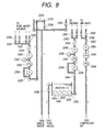
- Washing is carried out at the three stages comprising a pure water shower vessel, a first warm water vessel and a second warm water vessel.
- the arrangement of washing is such that the pure water warmed is supplied to the second warm water vessel, its exhaust liquid is used in the first warm water vessel and further its exhaust water is used in the pure water shower vessel.
- a web is gradually washed with a higher purity water after the completion of electrodeposition in an electrodeposition vessel.
- the second warm water vessel uses the purest pure water.
- This pure water is supplied to a second warm water vessel outlet back face pure water shower 2309 and a second warm water vessel outlet surface pure surface shower 2310 directly before the withdrawal of the web.
- the pure water to be supplied is delivered from a water washing system pure water port 2337 through a water washing system pure water supply source 2338, stored once in a pure water heating vessel 2339, warmed to a predetermined temperature by pure water heating vessel pure water heating heaters 2340 to 2343, passes through a pure water heating vessel pure water delivery valve 2344, a pure water heating vessel delivery pump 2346, a pure water heating vessel pressure switch 2347, a pure water heating vessel cartridge-type filter 2349 and a pure water heating vessel flow meter 2350, then partly delivered from a second warm water vessel outlet back face shower valve 2351 to a second warm water vessel outlet back face shower 2309 and the rest is delivered from a second warm water vessel outlet surface shower valve 2352 to a second warm water vessel outlet surface shower 2310.
- the pure water supplied to the shower and accumulated in the second warm water vessel retaining vessel 2317 forms a pure water rinse bath, in which the web is washed with still water.
- a second warm water vessel warm water temperature-retaining heater 2307 is provided at the second warm water vessel.
- the pure water overflown from the second warm water vessel retaining vessel 2317 is supplied from the second warm water vessel 2362 via the liking tube 2232 between the warm water vessels.
- a first warm water vessel warm water temperature-retaining heater 2304 is provided so as to retain the temperature of the pure water r.
- an ultrasonic wave source 2306 is provided so as to positively remove the stain of the web back face between the first warm water vessel roller 2282 and the second warm water vessel shuttle entry roller 2283.
- the pure water from the first warm water vessel retaining vessel 2316 is delivered through a pure water shower vessel pure water shower supply pump 2325, a pure water shower vessel pure water shower supply pressure switch 2326, a pure water shower vessel pure water shower supply cartridge-type filter 2328 and a pure water shower vessel pure water shower supply flow meter 2329, then from a pure water shower vessel inlet surface pure water shower valve 2330 to a pure water shower vessel inlet surface pure water shower 2299, from a pure water shower vessel inlet back face pure water shower valve 2331 to a pure water shower vessel inlet back face pure water shower 2300, from a pure water shower vessel outlet back face pure water shower valve 2332 to a pure water shower vessel outlet back face pure water shower 2302, from a pure water shower vessel outlet surface pure water shower valve 2333 to a pure water shower vessel outlet surface pure water shower 2303, while cleaning shower flows are applied to the web surface and the web back face respectively at the inlet and the outlet of the pure water shower
- the water having finished showering is received by a pure water shower vessel receiver vessel 2315, joins part of the first warm water vessel warm water retaining vessel 2316 and a second warm water vessel warm water retaining vessel 2317 and is discarded to the water washing system drainage 2336. Normally, since ions or others are contained in the cleaning finished water, a given treatment is required.
- a web is delivered through the pure water shower vessel shuttle entry roller 2279, the pure water shower vessel roller 2280, the first warm water vessel shuttle entry roller 2281, the first warm water vessel roller 2282, the second warm water vessel shuttle entry roller 2283 and the second warm water vessel roller 2284 to the dry shuttle roller 2285.
- a pure water shower vessel back face brush 2298 is provided so as to remove the relatively large grain-size powder adhered to the web back face and products weak in adhesive force.
- the web having arrived at the drying section 2363 is dehydrated by means a drying section inlet back face air knife 2311 and a drying section inlet back face air knife 2312.
- Introduction of air into the air knife is carried out in a route comprising a drying system compressed air introducing port 2353, a drying system compressed air pressure switch 2354, a drying system compressed air filter regulator 2355, a drying system compressed air mist separator 2356 and a drying system compressed air supply valve 2357 followed by a drying section inlet back face air knife valve 2358 or a drying section inlet back face air knife valve 2359. Since especially the water content of the air supplied to the drying section is unfavorable, the role of the drying system compressed air mist separator 2356 is important.
- drying by means of radiation heat of lining-up IR lamps 2313 is performed. If the radiation heat of IR lamps is sufficient, no unfavorable effect is caused even if an electrodeposition film is cast into a vacuum device such as CVD device.
- a vacuum device such as CVD device.
- generation of a mist due to the dehydration and generation of a water vapor by the IR lamp radiation takes place and the drying section vent 2314 linked with the exhaust duct is indispensable.
- the water vapor collected in the drying exhaust duct 2370 mostly returns to liquid water at the drying system condenser 2371 and is discarded to a drying system condenser exhaust water drain 2373 and partly to a drying system exhaust air 2374. If a harmful gas is contained in water vapor, the exhaust air should be subjected to a given treatment.
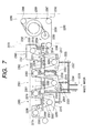
- the wind-up apparatus 2296 winds up the web 2006 on a web winding bobbin 2289 in the shape of a coil. If protection of the deposited layer is necessary, an interleaf is drawn out from an interleaf draw-out bobbin 2290 and wound into the web as shown in Fig. 7.
- the conveying direction of the web 2006 is indicated by Arrowhead 2292
- the rotating direction of the web winding bobbin 2289 is indicated by Arrowhead 2293
- the wind-up direction of the interleaf draw-out bobbin 2289 is indicated by Arrowhead 2294.
- the whole wind-up apparatus is so structured as to be covered with a wind-up apparatus clean booth 2295 using a HEPA filter and a down flow.
- a function of correcting the meander of a web is afforded to the wind-up apparatus direction converting roller 2287.
- the wind-up apparatus direction converting roller 2287 is swung around the pivot axis set at the side of the wind-up apparatus entry roller 2286 by an hydraulic servo, thereby enabling the correction of a meander.
- the control of the wind-up apparatus direction converting roller 2287 is approximately the move of the roller to this side or to the inner side, whose direction is opposed to the direction of web meander detected from the meander detector.
- the gain of a servo depends on the conveying rate of a web, but is generally not required to be large. Even when winding up a several hundred meter long web, its end face can be aligned at a precision of sub-millimeter.
- the pivot axis actually employed is 2 m long to the web upstream side and is 2 m or longer toward the rollers before and behind the wind-up apparatus direction converting roller 2287, so that no ear wave occurs even if a meander correction for the end alignment is made within the width of several mm. This becomes apparent by the analysis mentioned above. Besides, use of a reflection type laser position detector for the meander detection is favorable from the viewpoint of precision.
- Exhaust ports linked with such exhaust ducts include a first electrodeposition vessel upstream exhaust port 2021, a first electrodeposition vessel midstream exhaust port 2022 and a first electrodeposition vessel downstream exhaust port 2023 of the first electrodeposition vessel 2066, a second electrodeposition vessel upstream exhaust port 2071, a second electrodeposition vessel midstream exhaust port 2072 and a second electrodeposition vessel downstream exhaust port 2073 of the second electrodeposition vessel 2116, a pure water shower vessel exhaust port 2301 of the pure water shower vessel 2360, a first warm water vessel exhaust port 2305 of the first warm water vessel 2361 and a second warm water vessel exhaust port 2308 of the second warm water vessel 2308.
- the water vapor collected at an electrodeposition vessel system and water washing vessel system exhaust duct 2020 passes through an insulating flange, mostly returns to liquid water at an electrodeposition water washing system exhaust duct condenser 2366 and is discarded to an electrodeposition water washing system exhaust duct condenser exhaust water drain 2368 and partly to an electrodeposition water washing system exhaust air 2369. If a harmful gas is contained in water vapor, the exhaust air should be subjected to a given treatment.
- an electrodeposition water washing system exhaust duct trunk insulating flange 2365 and an electrodeposition water washing system exhaust duct water washing side insulating flange 2364 were provided to keep the first electrodeposition bath retaining vessel 2065 of the first electrodeposition bath 2066 and the second electrodeposition bath retaining vessel 2115 of the second electrodeposition bath 2116 at a float potential apart from the ground connection, so that the exhaust ducts were electrically separated from both retaining vessels.
- an object of the present invention is to provide a web conveying apparatus capable of, in formation of a functional film, conveying a web, which is treated by winding in a coil shape, without occurrence of an ear wave in a predetermined speed and keeping a distance from an opposite electrode for film formation without snaking.
- an electrodeposition apparatus formable at low cost does not require a rigid chamber like that of a vacuum film formation apparatus. Therefore, a part supporting a roller is adapted to be deformed by a temperature and a tension. In this case, supplying an enough conveying apparatus is important.
- Another object, in consideration of the above described problem, of the present invention is to provide a continuous electrodeposition apparatus and a continuous electrodeposition method, for an oxide film, capable of flowing an even and stable electrodeposition current to electrodeposit continuously an even zinc oxide film on an elongated substrate.
- the present invention provides a web conveying apparatus for holding and conveying a web while applying tension to the web, wherein the conveying apparatus has a plurality of rollers conveyed by contacting with the web and a mechanism for limiting deformation of the web to Y/E or smaller by at least one of the rollers, where Y is yield strength of the web and E is Young's modulus of the web.
- a preferable embodiment of such web conveying apparatus exemplified by the above described mechanism is a mechanism for controling inclination of an axis of the roller having the mechanism.
- one having a snaking-correction mechanism to correct snaking of the above described web and one, in which the snaking-correction mechanism comprising a displacement detection signal generating device using a laser sensor and an arc motion roller for giving a motion in direction opposite to displacement to the above described web on the basis of the displacement detection signal, are also preferable.
- the mechanism for controlling inclination of the axis of the above described roller is a mechanism for controlling inclination of the axis by vertically moving one end of the axis and using the other end of the axis as a fulcrum
- one having a inclination detection mechanism employing a noncontact sensor one having the servo-moving mechanism having a plurality of discrete control amounts, one having the servo-moving mechanism with a continuous control amount, and one having the servo-moving mechanism and a mechanism for preventing a maximum control amount due to the servo-moving mechanism from exceeding yield stress of edges of the web are all exemplified as preferable implementations.
- One having mechanism for controlling tension applied to the above described web to 0.49 N or more per 1-cm web width, and one for keeping difference between inclination of the axis of the roller having the above described mechanism for controlling the inclination of the axis of the above described roller and inclination of the axes of preceding and succeeding rollers to 1.025/1000 radian or smaller are also preferable. It is further preferable that the roller having the mechanism to control inclination of the axis of the above described roller is an electrical supply roller.
- the present invention provides the electrodeposition apparatus having the above described web conveying apparatus, an electrodeposition vessel to hold an electrodeposition bath in which electrodeposition is carried out by dipping the web, and en electrode for electrodeposition.
- the present invention provides the web conveying method using the electrodeposition apparatus to hold the web and convey by applying tension to the web, wherein the electrodeposition apparatus has a plurality of rollers to be conveyed by contacting with the web and carries out conveyance by suppressing deformation in a ranfe of Y/E or less by the mechanism installed in at least one roller of the rollers.
- conveyance is carried out by correcting snaking of the above described web by the snaking-correction mechanism and more preferable that the above described snaking-correction mechanism has the displacement detection signal generating apparatus using the laser sensor and the arc motion roller to move the arc motion roller and give the motion in direction opposite to displacement to the above described web on the basis of the displacement detection signal, are more preferable.
- conveyance is carried out by moving the one end vertically using the other end, as the fulcrum, of the axis of the roller.
- the mechanism to control inclination of the axis of the above described roller has the inclination detection mechanism employing the noncontact sensor and conveyance is carried out through monitoring inclination of the axis by the detection mechanism, the mechanism to control inclination of the axis of the above described roller has the servo-moving mechanism and the mechanism to control the maximum control amount by the servo-moving mechanism to suppress in a range of not more than the yield stress of the edges of the web are all exemplified as preferable implementations and conveyance is carried out by controlling deformation of the web to suppress in a range of not more than the yield stress of the edges of the web by these mechanisms, conveyance is carried out controlling tension applied to the above described web in a range of 0.49 N or higher per 1-
- the present invention provides the electrodeposition method characterized in that the web is conveyed to pass through the electrodeposition bath by the above described web conveying method and a film is formed on the web by electrodeposition.
- the web-conveying apparatus comprising a wind-up roller for giving a driving force for conveying in a predetermined speed the web to treat by winding in the coil form and for winding up a treated web by arranging the end thereof, a delivery roller (wind-off roller) for continuously deliverying the web while holding an untreated web and applying tension to the web between the derivery roller the wind-up roller, a plurality of follower rollers for changing a travelling direction of the web, which is conveyed in a predetermined speed while the tension is kept by the wind-up roller and the delivery roller, according to treatment of the web, and a snaking-correction means for winding up the web by arranging the end thereof by the wind-up roller, wherein at least one roller of a plurality of the above described follower rollers has means for suppressing the web deformation amount caused by roller axes in a range of Y/E or less, where Y is yield strength of the web
- the snaking-correction means of the web comprises the displacement detection signal generating apparatus using the laser sensor and the arc motion roller to give the motion in the direction opposite to displacement to the web on the basis of the displacement detection signal.
- the above described axis inclination-controlling means is the means to control inclination of the axis of the roller by moving the one end vertically using the other end, as the fulcrum, of the roller axis of the follower roller.
- the above described axis inclination-controlling means comprises inclination detection means employing the noncontact sensor and servo-moving means having a plurality of the discrete control amount.
- the above described axis inclination-controlling means comprises inclination detection means employing the noncontact sensor and the servo-moving means having a continuous control amount.
- the maximum control amount by the above described servo-moving means does not exceed the yield stress of the edges of the web.
- the present invention provides the electrodeposition apparatus having such the web-conveying apparatus.
- Another continuous electrodeposition apparatus is a continuous electrodeposition apparatus in which a current is applied between a web (elongated substrate) soaked in an electrodeposition bath and an anode to deposit continuously electrochemically a film on the elongated substrate, wherein a tension is applied to the elongated substrate and the elongnated substrate is conveyed by winding a part thereof around an electrical supply roller, which feeds or receives all currents for electrodeposition through a feeding means, wherein inclination between the axis of the electrical supply roller and the axes of preceding and succeeding rollers during conveyance thereof is kept to a predetermined angle or smaller which is determined based on a ratio the yield strength to Young's modulus of the elongated substrate.
- tension applied to the elongated substrate is 0.49 N or more per 1-cm width of the substrate.
- inclination between the axis of the electrical supply roller and the axes of preceding and succeeding rollers is kept to 1.025/1000 radian or smaller.
- the oxide film is preferably a zinc oxide film deposited in the electrodeposition bath containing at least a nitrate ion and a zinc ion.
- the elongated substrate is preferably a metal substrate.
- an elongated substrate to be conveyed and an anode opposite thereto are soaked in an electrodeposition bath, and a current is applied between the elongated substrate and the anode to deposit continuously an oxide film electrochemically on the elongated substrate, wherein a tension is applied to the elongated substrate, and the elongnated substrate is conveyed by winding a part thereof around an electrical supply roller, which feeds or receives all currents for electrodeposition through a feeding means, and inclination between the axis of the elecrtical supply roller and the axes of preceding and succeeding rollers during conveyance thereof is kept to a predetermined angle or smaller which is determined based on the ratio of the yield strength to Young's modulus of the elongated substrate.
- tension applied to the elongated substrate is 0.49 N or more per 1-cm width of the substrate.
- Ii is preferable that inclination between the axis of the electrical supply roller and the axes of preceding and succeeding rollers is kept to 1.025/1000 radian or smaller.
- the oxide film is preferably a zinc oxide film deposited in the electrodeposition bath containing at least nitrate ions and zinc ions.
- the inventors conducted the following examinations for creating the present invention.
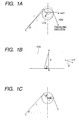
- Fig. 1A shows an attitude when the axis of the roller has tilted for 6 made by proceeding of the web 1006 with the width w, which has wound around the roller.
- a point C is a immobile point being such as the roller immediately before.
- the progressing direction P of the web 1006 tilts for ⁇ . If no friction is assumed between the roller and the web 1006, the progressing direction of the web 1006, tilted causes shift of the web conveyed in the speed vd/w [mm/min] (to the front in this case) on the roller.
- the Fig. 1C in the case where the roller axis tilts as s, treatment similar to motion like d is possible.
- This relation is same in lateral inclination of the roller axis.
- a left side is determined by material and shape of the web.
- the distance between rollers is determined at designing the apparatus. In other words, determination of the web and determination of the distance between rollers subsequently determine tolerance of deviation between roller axes. On the contrary, in order to allow deviation, the distance between rollers should be previously set to a large value. If allowable, it is possible to select an effective shape and material of the web after building up a film-forming apparatus.
- the distance between rollers can be set to the large one, or if deformation of the web can be reduced by decreasing tension applied to the web, the above requirement is relaxed. In addition, in the case where the web itself has elasticity, the requirement is not so strict.
- distortion the web deformation
- d/L the maximum distortion
- the tolerance distortion of the elongated substrate is 1.025/1000. It is 0.125 mm for a 1 m L.
- the elongated substrate receives tension of 9800 N enough to collide against each roller to conduct a conveyance experiment.
- the axis of a turning roller 2013 in an entrance of the electrodeposition vessel generates a 1.5-m shift toward the axis of the electrical supply roller, namely, an exhaust roller 2005 of the wind-off apparatus, relatively for the width of the electrodeposition vessel, to present a large variation of a feeding current in conveyance.
- this may cause a small thickness of the film, a high electric resistance, and a microscopic projection due to abnormal growth.
- the distance between the axis of the roller 2013 in the entrance of the electrodeposition vessel and the axis of the electrical supply roller, namely, the exhaust roller 2005 of the wind-off apparatus was 1 m and falls in the range of the present invention. Conveying the elongated substrate in this state showed a very stable and constant feeding current
- a main component of constitution of the web conveying apparatus of the present embodiment has basically similar constitution to that adopted to the electrodeposition apparatus shown in the Fig. 2 and Fig. 3 to Fig. 9.
- Various improvements have been made to solve a problem of the apparatus. Therefore, in convenience, description is given with reference numerals similar to those of the Fig. 2 and Fig. 3 to Fig. 9.
- the electrodeposition apparatus according to the present invention is that made by adopting roll-to-roll system to convey the web 2006 across rolls and for example, equipped as the main constitution component of the electrodeposition apparatus and thus, the web 2006 across rolls is flown from left to right in the Fig. 2, in order of the wind-off apparatus 2012, the first electrodeposition vessel 2066, the second electrodeposition vessel 2116, the pure water shower vessel 2360, the first warm water vessel 2361, the second warm water vessel 2362, the drying part 2363, and the wind-up apparatus 2296 to deposit a predetermined electrodeposited film
- the elongated substrate receives tension and also is conveyed in the form of partial winding around the electrical supply roller, which feeds or receives all currents for electrodeposition through feeding means, to be conveyed and inclination of the axes of the electrical supply roller and rollers therebefore and thereafter during conveyance thereof is kept to the predetermined angle or smaller which is determined based on the ratio of the yield strength to Young's modulus of the substrate.
- the web (elongated substrate) applied to the present invention are exemplified as applicable by metal such as stainless steel (SUS), iron, copper, aluminium, and brass, or those prepared by plating on a surface of them, and also paper and resin.
- metal such as stainless steel (SUS), iron, copper, aluminium, and brass, or those prepared by plating on a surface of them, and also paper and resin.
- SUS stainless steel
- iron, copper, aluminium, and brass or those prepared by plating on a surface of them
- paper and resin have a large elasticity range and therefore, particularly effective in case of small distance between rollers.
- a constant of a material of a web material is important and a surface property does not so much influence to.
- those electrically conductive to the surface of the film prepared and noncorrosive by the electrodeposition bath can be used and exemplified by metal such as stainless steel (SUS), Al, Cu, and Fe.
- metal such as stainless steel (SUS), Al, Cu, and Fe.
- SUS stainless steel
- Al aluminum
- Cu copper
- Fe copper
- coated with metal such as a PET film
- SUS is excellent as the elongated substrate for preparing a device in a postprocessing.
- SUS nonmagnetic SUS and magnetic SUS can be applied.
- the former is represented by SUS 304 excellent in grindability to allow making to a mirror face with about 0.1 s.
- SUS 430 of a ferrite series effectively used for conveyance by applying a magnetic force.
- the surface of the substrate may be smooth or coarse.
- changing a kind of a rolling roller causes a change of surface properties. That called BA has a near-mirror property and 2D shows a prominent irregular surface.
- SEM scanning electron microscope
- another conductive material may be prepared as the film to select for a purpose of electrodeposition.
- another conductive material may be prepared as the film to select for a purpose of electrodeposition.
- forming previously a very thin layer of zinc oxide by another method is preferable for improving stably the speed of deposition by the electrodeposition method.
- the electrodeposition method has a merit of a low cost.
- a costly method is applied additionally, when total reduction of the cost is possible, a combined use of these two systems is advantageous.
- Tension to stretch the elongated substrate across a bobbin 2001 of the elongated substrate of the wind-off apparatus and a wind-up bobbin 2289 for the elongated substrate is assigned to 0.49 to 490 N per 1 cm substrate width.
- tension is smaller than 0.49 N, the substrate is suddenly hung down, moves to outside of a predetermined conveying path, scratches an edge by moving out from the roller, or controllability of snaking correction is worsened distinctly.
- More preferable tension applied to the web is specified by settable value selected from values ranging from around 98 N to around 1176 N for the web made of SUS of the 0.125 mm thickness and the 356 mm width.
- tension set large requires a rigid frame corresponding to the roller axis, which supports the frame. Shift of the roller axis preferably ranges from 0.1 mm to 0.3 mm or less. Better means can be adjusting the roller axis in the state of applying tension. In this case, a time sequence must be watched.
- Tension can be generated by sliding of a force to wind up the wind-up bobbin 2289 for the elongated substrate and a crutch (a powder crutch and the like are effectively used) fitted to the axis of the bobbin 2001 of the elongated substrate of the wind-off apparatus.
- a crutch a powder crutch and the like are effectively used
- the conveying path does not almost change and intermediate rollers can be all assigned to the follower roller and therefore, freedom of designing arrangement of components, such as the roller, configuring conveyance system is very high; on other hand, at the time of no conveyance, no tension occurs and thus, for prevention of hanging down of the substrate in a still state, other lock means is necessary.
- Tension can be generated also by using a tension roller and the like capable of moving the axis thereof. In this case, controlling and monitoring tension can be readily performed; however, the position of the tension roller changes and hence, the design to keep a stroke thereof is required and the degree of parallelism of the roller changes to generate snaking.
- tension can be generated by moving positively an intermediate roller to a direction causable of friction with the substrate.
- the roller used for the apparatus shown in the Fig. 2 must satisfy functions such as determining the conveying path of the elongated substrate, and also applying an electric potential necessary for the elongated substrate, and no formation of a current stray path unnecessary.
- Determination of the elongated substrate is particularly important.
- a degree of parallelism must be, needless to say, in an early stage is and even if the temperature of the electrodeposition bath rises to a high temperature such as 90°C to cause thermal expansion of a large bath vessel, displacement of a position must be suppressed to a minimum degree. Practically, back lash of a submillimeter order can be allowed; however, for the parallelism, it is preferable that precision of the order of 100 minutes is kept at the time of rising of the temperature.
- the difference in the degree of parallelism and twist cause particularly a deviated position of the elongated substrate in the electrodeposition vessel and then, scratch and the wavy form of the Undaria pinnatifida thallus edge occurs very frequently.
- distortion becomes a problem. Therefore, in case of the large distance between rollers, inclination, namely the degree of parallelism, of the roller axis is not so important cause.
- the roller is a parallel roller and thus, surface processing is not especially necessary.
- a soft substrate such as an Al foil
- the roller In order to lift electrically, the roller can be prepared with a resin such as nylon or polyethylene and also, the axis of a metal roller can be prepared with the resin, and in addition, a resin member is put between parts, where the bearing has been installed, to realize insulation.
- a resin such as nylon or polyethylene
- the axis of a metal roller can be prepared with the resin, and in addition, a resin member is put between parts, where the bearing has been installed, to realize insulation.
- the snaking-correction roller which moves the substrate in the direction of correction, is installed.
- a direction-switching roller 2287 (refer to the Fig. 7) for the wind-up apparatus works for such operation.
- friction with the elongated substrate is larger.
- the elongated substrate slides on the roller for snaking correction.
- a magnitude of friction applied practically is experimentally determined including tension. Occasionally, the effect can be yielded by selecting the material to optimize friction with the substrate and processing to make the surface coarse.
- configuration may be build up to allow the whole roller to move in parallel and may allow a shape (named a tangent roller) to do oscillation motion around the axis, in a certain distant position, as the fulcrum.
- the parallel motion roller presents the effect to the large shift and on the other hand, the tangent roller allows the simplified configuration of the apparatus.
- the material of the supply roller applied to the present invention is not restricted as long as it can hold the web, and can apply a certain tension to the web by breaking against a wind-up force of the wind-up roller, and then can control a supply speed of the web. Breaking is normally by a crutch installed coaxially in the roller. Control of the supply speed is carried out by feed back a speed, which is detected by the speed sensor and a rotation encoder, to the driving system of the wind-up roller.
- the preferable wind-up roller applied to the present invention is that capable of conveying wind-up of the web by motor drive, and more preferable is that capable of controlling the rotation speed by the servo. In this case, a rotation speed signal from the supply roller can be fed back.
- the web passed through a snaking correction system is wound and thus, the edge is become that arranged. It is preferable that the conveying speed of the web wound up by the wind-up roller meets a speed of 200 mm to 500s mm per minute.
- the surface rotation precision must not exceed 1 mm to the distance of 1 m between rollers and preferably 0.3 mm or small. This is the distance including eccentric distance of the axis and hence, when a soft resin made bearing is used, this allowance may be exceeded by a temporal change.
- the bearing used is preferably of SUS-made or the like.
- the surface of the roller can be made of metal and also such resin as nylon; however, for example, the roller installed in the electrodeposition vessel is influenced by a solution, temperature, and tension and then, may cause rheological deformation beyond the allowance. Therefore, this has to be cautioned.
- the surface of the roller has a somewhat large friction with the web to disturb sliding. Therefore, the surface material used is nylon and SUS. In consideration of the surface quality of the web, if sliding is easy, a stronger tension should be applied.
- Axis inclination controlling means employed in the present invention is exemplified by an electric servo and a hydraulic servo or the like. Particularly, to give inclination of 1/1000 or fewer, a stroke of 1/1000 web width, i. e., normally from some ten micrometers to some hundred micrometers must be assured.
- Other useful system is to install a doctor guide in an upper limit and a lower limit and meet it with a top and a bottom.
- detection means In order to feed back a necessary signal for axis inclination controlling means, detection means is generally required. In this detection means, detecting the shift of the web is preferable and therefor, a laser edge position sensor and an eddy current and a magnetic sensor are applicable.
- the edge position of the laser sensor even either a reflection type or a transparent type, is suitable for the case requiring precision.
- the eddy current sensor is preferable in the case of a limited space for installation of the sensor.
- the magnetic sensor presents the effect to the magnetic web.
- the shift of the web caused by these detection means is set to have precision of at least some ten micrometers, preferably from 10 to 20 micrometers. These values can be set by using the above-enumerated sensors.
- the electrodeposition bath examined by using such small experiment apparatus as beaker can be used. Concerning zinc oxide deposition having irregular surface and having optical confinement effect applied to an unlerlaying layer of the solar cell, the solution disclosed in Japanese Patent Application Laid-Open No. 10-195693 can be used.
- electrodepositing zinc oxide a combination of zinc nitrate with an additive is preferably used and when the additive is a sugar, homogeneity of the film increases. Specifically, dextrin shows a prominent effect thereof.
- electrodeposition negative and positive electric potentials are applied to the elongated substrate and the anode, respectively to accelerate an electrochemical reaction.
- electrodeposition by current regulation is preferable. It is preferable to designate the electric current by a density and designation is done in a range from 0.3 to 100 mA/cm 2 .
- a zinc plate of purity from 2 N to 4 N can be used as a soluble anode.
- a feeding line to the anode is configured by tightening with a SUS bolt for assuring reliable electric contact during a long term.
- SUS and Pt can be used as an insoluble anode.
- wrapping the soluble anode in an anode bag preferably prevents the generated zinc oxide powder from being dispersed into the electrodeposition bath.
- the material of the anode bag cotton and amide resin fiber noncorrosive in the bath can be used and preparing it in a proper mesh structure is preferable.
- the size of the mesh is determined by designating the maximum size of power, of which surface is reliably contacted with the electrodeposition bath, generate dust. Normally, the size ranging from 0.5 mm mesh to some millimeters mesh is selected.
- each electric power supply has a float output.
- a suction type power supply In voltage regulation, in the case where a predetermined electric potential is applied, when there is a possibility of a flow of the current to a suction direction, a suction type power supply has to be adopted.
- Each power supply applies the electric potential to a single or a bundled plurality of anodes to flow the current.
- appearance of the current path to link anodes is preferably prevented as far as possible.
- installing such insulation plate as Teflon or vinyl chloride in the bath is effective.
- An ear wave-preventing apparatus has been assembled in a returning roller 2016 between the electrodeposition vessels of the Fig. 2.
- Fig. 10 shows attitude thereof.
- reference numeral 3005 denotes the returning roller 2016 (refer to the Fig. 4) between the electrodeposition vessels of the Fig. 2.
- the roller axis 3004 thereof is supported by the bearings 3003 and 3008.
- the bearing 3003 is installed in the frame of the apparatus 3001.
- the other bearing 3008 is installed in a bracket 3010.
- a slider 3012 of an LM guide comprising the slider 3012 and a rail 3011 has been installed.
- the rail 3011 of the LM guide is installed in the frame 3002 of the apparatus. According to this, motion of the bracket 3010 is limited to vertical motion. Therefore, the roller axis 3004 moves similar to an arrow 3009 around the bearings 3003.
- the bracket 3010 of which fixed end has been connected to an operation end of the electric servo 3013 installed in the frame 3002, is received a servo-working signal and gives a motion of the arrow 3014 and thus, controls inclination of the above described roller axis 3004.
- Detection of a web position is carried out by an eddy current displacement sensor 3016 mounted on a sensor supporting stand 3015 connected to the bracket 3010.
- An output of the eddy current displacement sensor 3016 is sent to a sequencer through a sensor amplifier 3017 and an analog controller 3018 as a web position signal.
- a cover 3007 is located to prevent to escape steam from the electrodeposition bath and also prevent drying of the web, and prevent attaching of dust to the web.
- the eddy current displacement sensor 3016 was a sensor EX022 manufactured by KEYENCE Corporation
- the amplifier 3017 was EX510 manufactured by the same corporation
- the analog controller 3018 was RDE50E manufactured by the same corporation.
- Advantages of the eddy current displacement sensor are installability in a small place, a good temperature characteristics, tolerability against introduced steam, and the like and preferably meets the followings: the cover is put over the returning roller 2016 between the electrodeposition vessels to inhibit to keep an enough space, the temperature of the electrodeposition bath is raised to 95°C, and steam from the electrodeposition bath may be introduced.
- shift of the web in the lateral direction ranging to 10 mm is converted to the voltage ranging from 0 to 10 V to output it. Resolution is 0.1 mm or higher and satisfactory for the purpose of the present invention.
- the electric servo 3013 used was MSM022AIF made by Panasonic. Continuous operation is possible; however, herewith, a stopper was used to make 3-value action with ⁇ 0.3 mm (including a neutral point.)
- the electric servo can be made in a small size to be convenient for installation on the bracket as in the present Example. If a weight of the roller is large, the hydraulic servo can be used.
- As the LM guide SR30TB made by THK Corporation was used. The stroke was enough including freeplay at installation.
- Feed back of the servo by the controlling system of the sequencer comes in a center of the servo in the case, where the output from the eddy current displacement sensor is ⁇ 1 mm, and comes in just 0.3 mm of a reverse direction in exceeding 1 mm.
- roller axis inclination controlling system is incorporated in the electrodeposition apparatus shown in the Fig. 2 and in the state of the temperature of the electrodeposition bath being a room temperature, the web was manually set. Thereafter, tension of about 980 N was applied to the web to convey preliminarily. At this time, all the roller had completed alignment in horizontal direction. As a result of preliminary conveyance, unless the roller axis inclination controlling means according to the present invention is worked, good conveyance was yielded. Shift of the web in the part, of which snaking was corrected by using the direction-switching roller 2287 for the wind-up apparatus, fell in about ⁇ 2 mm and the web was wound in the coil form having the arranged edge of the web.
- the temperature of the electrodeposition bath was raised to 85°C; the electrodeposited film was deposited to carry out conveyance of the web.
- shift of the web in the part, of which snaking was corrected by using the direction-switching roller 2287 for the wind-up apparatus increased to about ⁇ 6 mm and thus, though snaking of the web can be corrected, the ear wave occurred and a following process did not allow it.
- tension was reduced to about 588 N, shift of the web reduced to ⁇ 5 mm; however, the ear wave was inherently left unremoved.
- the roller axis inclination controlling means as described above as the present example was worked and then, after 10 minutes, snaking of the whole web reduced and shift of the web in the part, of which snaking was corrected by using the direction-switching roller 2287 for the wind-up apparatus, fell in about ⁇ 2 mm and as the result, the web was wound in the coil form having the arranged edge of the web.
- the film electrodeposited faces to a face, in which shift is corrected by an inclination angle-controlling roller.
- the roller is the follower and the force in the direction of scratching on the film surface does not work (the web is conveyed facing closely to the roller) and therefore, crack and crush never occurred to influence to a function.
- Example 1 The same control system as that incorporated in Example 1 was employed by modifying only a feed back system of the servo to a continuous system shown in the Fig. 11.
- the web was set when the electrodeposition bath was in the room temperature.
- the preliminary conveyance showed good conveyance similar to Example 1 including wind-up without the ear wave.
- the web conveyance was carried out after the temperature of the electrodeposition bath was raised to 85°C and then, similar to Example 1, shift of the web in the part, of which snaking was corrected by using the direction-switching roller 2287 for the wind-up apparatus, increased to about ⁇ 6 mm.
- roller axis inclination controlling means was worked and then, after 5 minutes earlier than Example 1, snaking of the whole web reduced and shift of the web in the part, of which snaking was corrected by using the direction-switching roller 2287 for the wind-up apparatus, fell in about ⁇ 2 mm and as the result, the web was wound in the coil form having the arranged edge of the web.
- Example 2 The same control system as that incorporated in Example 1 was incorporated in a returning forwarding roller 2279 (refer to Fig. 7) of the pure water shower vessel of the electrodeposition apparatus shown in the Fig. 2.
- the reference numeral 4002 is the substrate, 4003 is a reflection metal layer, 4004 is a spattered zinc oxide film, 4005 is the electrodeposited zinc oxide film, 4006 is an n type layer, 4007 is an i type layer, 4008 is a p type layer, 4009 is an ITO layer.
- the electrodeposition bath containing zinc nitrate of a 0.2 mol/L concentration and 0.07 g/L dextrin was circulated in a first electrodeposition vessel 2066 and a second electrodeposition vessel 2116 and kept the temperature thereof to 85°C, respectively.
- the conveyance speed was 500 mm/min
- tension was 588 N (about 16.5 N per 1 cm substrate width)
- all anode current (a sum of currents flowing in all anodes located in the first electrodeposition vessel 2066 and the second electrodeposition vessel 2116) of 176 A was fed (practically, the direction of the current is the direction from the substrate toward the electrical supply roller and hence, receiving is a correct expression; however, the anode is herewith needless to distinguish from cathode and therefore, currents of either directions are named "feeding" from the exhaust roller 2005 of the wind-off apparatus used as the electrical supply roller to electrodeposit continuously the zinc oxide film, 4005.
- shift of the axis of the rollers before and after the electrical supply roller are both 0.7/1000 or smaller and the elongated substrate showed shift of the conveying path of the maximum 2 mm, showed snaking better corrected, and wound up around an elongated substrate wind-up bobbin 2289 in a ⁇ 3 mm precision.
- the elongated substrate, on which the electrodeposited zinc oxide film 4005 was formed by such manner was set in a elongated substrate CVD film preparing apparatus not illustrated to form sequentially and continuously a 300 ⁇ n type amorphous silicon layer 4006, a 2000 ⁇ i type amorphous silicon layer 4007, and a 200 ⁇ p type microcrystal silicon layer 4008.
- a 660 ⁇ ITO film 4009 was formed to yield the solar cell 3001 of the configuration shown in the Fig. 12.
- the elongated substrate completed was sampled in the length direction, an output electrode was configured as the solar cell under an AM 1.5 imitation sunray to evaluate thermal conversion efficiency by IV measurement and on the basis of deviation thereof applicability of the electrodeposition layer wad evaluated by the electrodeposition apparatus of the Fig. 2.
- solar cell could be formed in 800 m part of the 1050 m elongated substrate, because a leader part of the apparatus is essential. The solar cell conversion efficiency was examined for this 800 m and then, almost stable production ranging from 7.5 to 7.9 percent was possible.
- the solar cell of the Fig. 12 was prepared for 800 m length by the same method.
- the solar cell conversion efficiency was examined by a similar manner to Example 4 and then, average value raged from 7.4 to 7.9 percent.
- a shunt, efficiency decreased by deficiency of a current density, and the like were found.
- Tension of the substrate installed in the electrodeposition apparatus of the Fig. 2 (from Fig. 3 to Fig. 9) in Example 4 was increased to a range from 588 N to 980 N (about 27.5 N per the 1 cm substrate width) to prepare a similar solar cell. Shift of the exhaust roller 2005 of the wind-off apparatus, used as the electrical supply roller, from the axis of the rollers before and after the electrical supply roller were increased up to 1.0/1000 and contact with the electrical supply roller of the substrate showed further improved reliability for that length. By this, the solar cell for 800 m length shown in the Fig. 12 was prepared through the process same as Example 4.
- the solar cell conversion efficiency for 800 m was 7.6 to 8.0 percents somewhat increased than Example 4. From examination of IV characteristics, this is caused by short current density Jsc improved.
- tension increased for the elongated substrate caused stable state of the distance between anode substrates for a long period on the basis of almost no influence by stirring of the bath for a long time. Therefore, stable formation of the electrodeposited zinc oxide film was realized.
- Thickness of the SUS substrate used was increased to the range from 0.125 to 0.15 mm. This is for a main purpose to increase independence as the solar cell. However, a size of the coil restricted the length allowing formation of the solar cell film to 600 m.
- deformation allowance namely, allowance of shift of the axis of rollers before and after the electrical supply roller, according to the present invention does not change.
- Changeable is tension causing the same change.
- the present example requires 1176 N tension not 980 N to bring the same deformation of the substrate as that of Example 5.
- Increase in tension causes a larger deformation of the roller axis.
- increase in rigidity of the frame supporting the axis is not realistic and therefore, the distance between rollers was let meet the range from 1 m to 1.5 m. According to this, the maximum distortion fell in 0.8/1000 and did not exceed the predetermined Y/E.
- the conveyance system by which the web to be treated in a wound form like the coil can be conveyed in the predetermined speed, without the ear wave, keeping the distance from a film-forming opposite electrode, and without snaking, can be provided in the form capable of incorporation in the film-fabricating apparatus.
- this system has the snaking correction means and the inclination control means of the arc motion roller and thus, even if inclination of the roller axis occurs according to the temperature change, tension change, and temporal change, the conveying system capable of wind-up the web, without the ear wave and snaking, can be provided.
- the servo feed back controls the noncontact sensor and a plurality of discrete control amounts and therefore, the detection part can be installed in a smaller space and also a simple algorithm realizes control.
- a response time from shift of the web to return to the predetermined path can be made short.
- the maximum control by the inclination control means does not exceed the yield stress of the edge of the web and therefore, the ear wave is not caused by the inclination control means
- the zinc oxide film allowing flow of the current for electrodeposition to the elongated substrate uniformly and stably, without occurrence of abnormal growth, and uniform film thickness and electric resistance can be continuously electrodeposited.
- the present invention can, by making inclination of the axis of the electrical supply roller and the rollers therebefore and thereafter 1.025/1000 (radian) or smaller, make an area around the electrical supply roller in both sides of the elongated substrate uniform, the uniform current can be kept across a width direction of the elongated substrate, and therefore, the zinc oxide film uniform in the width direction can be electrodeposited continuously.
- the present invention provides a web conveying pparatus for conveying a web while holding the web and pplying tension to the web, wherein the conveying pparatus has a plurality of rollers with which the web ontacts to be conveyed, and at least one roller of the lurality of rollers has a mechanism for limiting deformation of the web within Y/E, and a web conveying method using a web conveying apparatus for conveying a web while holding the web and applying tension to the web, wherein the conveying apparatus has a plurality of rollers with which the web contacts to be conveyed, and the web is conveyed while the deformation of the web is limited within Y/E by a mechanism that is provided for at least one roller of the plurality of rollers.
Landscapes
- Engineering & Computer Science (AREA)
- Mechanical Engineering (AREA)
- Electroplating Methods And Accessories (AREA)
- Registering, Tensioning, Guiding Webs, And Rollers Therefor (AREA)
- Winding, Rewinding, Material Storage Devices (AREA)
- Advancing Webs (AREA)
Abstract
Description
Claims (40)
- A web conveying apparatus for conveying a web while holding the web and applying tension to the web, wherein the conveying apparatus comprises a plurality of rollers with which the web contacts to be conveyed, and at least one roller of the rollers comprises a mechanism to limit deformation of the web to Y/E or less, where Y is yield strength of the web and E is Young's modulus of the web.
- The web conveying apparatus according to claim 1, wherein the mechanism is a mechanism for controlling inclination of an axis of the roller having the mechanism.
- The web conveying apparatus according to claim 1, comprising a meandering correction mechanism that corrects meandering of the web.
- The web conveying apparatus according to claim 3, wherein the meandering correction mechanism comprises a displacement detection signal generator for generating displacement detection signal with laser sensor and an arc motion roller that provides the web an motion opposite to displacement of the web based on the displacement detection signal.
- The web conveying apparatus according to claim 2, wherein the mechanism for controlling the inclination of the axis of the roller is a mechanism for controlling the inclination of the axis by moving upward or downward one end of the axis of the roller with supporting other end of the axis of the roller.
- The web conveying apparatus according to claim 2, wherein the mechanism for controlling the inclination of the axis of the roller has an inclination detection mechanism with a non-contact sensor.
- The web conveying apparatus according to claim 2, wherein the mechanism for controlling the inclination of the axis of the roller has a servo motion mechanism with a plurality of discrete control amounts.
- The web conveying apparatus according to claim 2, wherein the mechanism for controlling the inclination of the axis of the roller has a servo motion mechanism with continuous control amounts.
- The web conveying apparatus according to claim 2, wherein the mechanism for controlling the inclination of the axis of the roller has a servo motion mechanism and a mechanism for preventing a maximum control amount due to the servo motion mechanism from exceeding yield stress of edges of the web.
- The web conveying apparatus according to claim 1, wherein the tension applied to the web is controlled such that it is 0.49N or more for 1 cm of the web width.
- The web conveying apparatus according to claim 2, further comprising a mechanism for maintaining difference in inclination between the axis of the roller having the mechanism for controlling the axis of the roller and axes of preceding and succeeding rollers within 1.025/1000 radian.
- The web conveying apparatus according to claim 2, wherein the mechanism for controlling the inclination of the axis of the roller is an electrical supply roller.
- An electrodeposition apparatus comprising a web conveying apparatus according to any one of claims 1 to 12, an electrodeposition vessel holding a electrodeposition bath in which electrodeposition is performed with the web being immersed, and an electrode for the electrodeposition.
- A web conveying method comprising using an apparatus for conveying a web while holding the web and applying tension to the web, wherein the conveying apparatus comprises a plurality of rollers with which the web contacts to be conveyed, and the web is conveyed while deformation of the web is limited to Y/E or less by a mechanism provided for at least one roller of the rollers, where Y is yield strength of the web and E is Young's modulus of the web.
- The web conveying method according to claim 14, wherein inclination of an axis of the roller having the mechanism is controlled by the mechanism.
- The web conveying method according to claim 14, wherein the web is conveyed with the web meandering being corrected by a web meandering correction mechanism.
- The web conveying method according to claim 16, wherein the meandering correction mechanism comprises a displacement detection signal generator for generating displacement detection signal with laser sensor and an arc motion roller, and the web is conveyed with the mechanism providing the web an motion opposite to displacement of the web by moving the arc motion roller based on the displacement detection signal.
- The web conveying method according to claim 15, wherein the web is conveyed while the mechanism for controlling the inclination of the axis of the roller moves upward or downward one end of the axis of the roller with supporting other end of the axis of the roller.
- The web conveying method according to claim 15, wherein the mechanism for controlling the inclination of the axis of the roller has an inclination detection mechanism with a non-contact sensor, and the web is conveyed with the detection mechanism monitoring the inclination of the axis.
- The web conveying method according to claim 15, wherein the mechanism for controlling the inclination of the axis of the roller has a servo motion mechanism and a mechanism for preventing a maximum control amount due to the servo motion mechanism from exceeding yield stress of edges of the web, and the web is conveyed with these mechanisms such that the stress of the web edges do not exceed the yield stress.
- The web conveying method according to claim 15, wherein the web is conveyed while the tension applied to the web is controlled such that it is 0.49N or more for 1 cm of the web width.
- The web conveying apparatus according to claim 15, wherein the web is conveyed while difference in inclination between the axis of the roller having the mechanism for controlling the axis of the roller and axes of preceding and succeeding rollers is maintained within 1.025/1000 radian.
- The web conveying method according to claim 15, wherein the web is conveyed while the mechanism for controlling the inclination of the axis of the roller controls inclination of an axis of an electrical supply roller.
- An electrodeposition method comprising conveying a web by a web conveying method according to any one of claims 14 to 23 such that the web passes through an electrodeposition bath, and depositing a film on the web by electrodeposition.
- A web conveying apparatus comprising:a wind-up roller for providing driving force to convey a web handled in coil form at a predetermined speed and winding up a processed web with alignment of edges of the web;a delivery roller for continuously delivering the web with holding an unprocessed web and applying tension to the web between the wind-up roller and the delivery roller;a plurality of follower rollers for converting a traveling direction of the web conveyed at the predetermined speed, tension of which is maintained between the wind-up roller and the delivery roller; anda meandering correction direction means for allowing the wind-up roller winding up the web with edge alignment,wherein at least one roller of the plurality of follower rollers is provided with an axis inclination control means for controlling an axis of the roller while limiting deformation of the web between the rollers to Y/E or less, where Y is yield strength of the web and E is Young's modulus of the web.
- The web conveying apparatus according to claim 25, wherein the meandering correction mechanism comprises a displacement detection signal generator for generating displacement detection signal with laser sensor and an arc motion roller that provides the web an motion opposite to displacement of the web based on the displacement detection signal.
- The web conveying apparatus according to claim 25, wherein the axis inclination control means is means for controlling the inclination of the axis of the follower roller by moving upward or downward one end of the axis of the follower roller with supporting other end of the axis of the follower roller.
- The web conveying apparatus according to claim 25, wherein the axis inclination control means comprises an inclination detection means with a non-contact sensor and a servo motion means with a plurality of discrete control amounts.
- The web conveying apparatus according to claim 25, wherein the axis inclination control means comprises an inclination detection means with a non-contact sensor and a servo motion means with continuous control amount.
- The web conveying apparatus according to claim 25, wherein the axis inclination control means comprises a servo motion means, and a maximum control amount due to the servo motion means does not exceed yield stress of edges of the web.
- A continuous oxide-film electrodeposition apparatus for continuously electrodepositing an oxide film electrochemically on an elongated substrate with applying electric current between the elongated substrate to be immersed in a electrodeposition bath and an anode,
wherein the elongated substrate is conveyed while tension is applied to the elongated substrate and a portion of the substrate is wound on an electrical supply roller that feeds or receives all electrodeposition current via an electrical supply means, and wherein inclinations of the electrical supply roller with respect to preceding and succeeding rollers during conveying are maintained within a predetermined angle that is determined based on a ratio of yield strength to Young's modulus of the elongated substrate. - The continuous oxide-film electrodeposition apparatus according to claim 31, wherein the tension applied to the elongated substrate is 0.49N or more for 1 cm of the web width.
- The continuous oxide-film electrodeposition apparatus according to claim 31, wherein the inclinations of the electrical supply roller with respect to preceding and succeeding rollers during conveying are maintained within 1.025/1000 radian.
- The continuous oxide-film electrodeposition apparatus according to claim 31, wherein the oxide film is a zinc oxide film deposited in an electrodeposition bath containing at least nitrate ion and zinc ion.
- The continuous oxide-film electrodeposition apparatus according to claim 31, wherein the elongated substrate is a metal substrate.
- A continuous oxide-film electrodeposition method for continuously electrodepositing an oxide film electrochemically on an elongated substrate with immersing the elongated substrate to be conveyed and an anode opposing thereto and applying electric current between the elongated substrate and the anode,
wherein the elongated substrate is conveyed while the tension is applied to the elongated substrate and a portion of the substrate is wound on an electrical supply roller that feeds or receives all electrodeposition current via an electrical supply means, and wherein inclinations of the electrical supply roller with respect to preceding and succeeding rollers during conveying are maintained within a predetermined angle that is determined based on a ratio of yield strength to Young's modulus of the elongated substrate. - The continuous oxide-film electrodeposition method according to claim 36, wherein the tension applied to the elongated substrate is 0.49N or more for 1 cm of the web width.
- The continuous oxide-film electrodeposition method according to claim 36, wherein the inclinations of the electrical supply roller with respect to preceding and succeeding rollers during conveying are maintained within 1.025/1000 radian.
- The continuous oxide-film electrodeposition method according to claim 36, wherein the oxide film is a zinc oxide film deposited in an electrodeposition bath containing at least nitrate ion and zinc ion.
- The continuous oxide-film electrodeposition method according to claim 36, wherein the elongated substrate is a metal substrate.
Applications Claiming Priority (6)
| Application Number | Priority Date | Filing Date | Title |
|---|---|---|---|
| JP2000087760 | 2000-03-28 | ||
| JP2000087760 | 2000-03-28 | ||
| JP2000201827 | 2000-07-04 | ||
| JP2000201827 | 2000-07-04 | ||
| JP2001075650A JP2002080151A (en) | 2000-03-28 | 2001-03-16 | Device and method for carrying web, and device and method for electrodeposion |
| JP2001075650 | 2001-03-16 |
Publications (2)
| Publication Number | Publication Date |
|---|---|
| EP1149789A2 true EP1149789A2 (en) | 2001-10-31 |
| EP1149789A3 EP1149789A3 (en) | 2003-08-13 |
Family
ID=27342817
Family Applications (1)
| Application Number | Title | Priority Date | Filing Date |
|---|---|---|---|
| EP01107585A Withdrawn EP1149789A3 (en) | 2000-03-28 | 2001-03-27 | Web conveying apparatus, and apparatus and method for electrodeposition using web conveying apparatus |
Country Status (5)
| Country | Link |
|---|---|
| US (1) | US6752915B2 (en) |
| EP (1) | EP1149789A3 (en) |
| JP (1) | JP2002080151A (en) |
| CN (1) | CN1187247C (en) |
| AU (1) | AU3134701A (en) |
Cited By (1)
| Publication number | Priority date | Publication date | Assignee | Title |
|---|---|---|---|---|
| CN109991157A (en) * | 2019-04-08 | 2019-07-09 | 中国核动力研究设计院 | A kind of high-temperature high pressure water corrosion product dissolution release device |
Families Citing this family (38)
| Publication number | Priority date | Publication date | Assignee | Title |
|---|---|---|---|---|
| JP2001134126A (en) * | 1999-11-05 | 2001-05-18 | Ricoh Co Ltd | Fixing roller and method of manufacturing the same |
| US7130020B2 (en) * | 2003-04-30 | 2006-10-31 | Whitney Theodore R | Roll printer with decomposed raster scan and X-Y distortion correction |
| US20050008821A1 (en) * | 2003-07-07 | 2005-01-13 | Pricone Robert M. | Process and apparatus for fabricating precise microstructures and polymeric molds for making same |
| US8226880B2 (en) * | 2003-07-07 | 2012-07-24 | 10X Technology, Llc | Process for fabricating precise microstructures |
| KR100990720B1 (en) | 2003-08-19 | 2010-10-29 | 주식회사 포스코 | Strip meander detection / calibration device for cold rolled roofers |
| EP1589130B1 (en) * | 2004-04-13 | 2009-07-29 | Applied Materials GmbH & Co. KG | Guide arrangement with at least one guide roll for guiding webs in web treating apparatuses |
| US7611584B2 (en) | 2005-12-13 | 2009-11-03 | Lg Electronics Inc. | Electroless metal film-plating system |
| CN101573477B (en) * | 2006-12-28 | 2011-01-19 | 日矿金属株式会社 | Roll unit for use in surface treatment of copper foil |
| JP4982313B2 (en) * | 2007-09-20 | 2012-07-25 | リョービ株式会社 | Transfer film winding method and printing paper transfer device |
| JP4683060B2 (en) * | 2008-03-17 | 2011-05-11 | トヨタ自動車株式会社 | Web conveyance device and web conveyance control method |
| US20100200413A1 (en) * | 2009-02-11 | 2010-08-12 | United Solar Ovonic Llc | Solution deposition method and apparatus with partiphobic substrate orientation |
| US9105778B2 (en) * | 2009-06-12 | 2015-08-11 | Apollo Precision (Kunming) Yuanhong Limited | Systems methods and apparatuses for magnetic processing of solar modules |
| US8062384B2 (en) * | 2009-06-12 | 2011-11-22 | Miasole | Systems, methods and apparatuses for magnetic processing of solar modules |
| JP5654270B2 (en) * | 2010-06-25 | 2015-01-14 | 株式会社シマノ | Fishing reel |
| CN102485964A (en) * | 2010-12-02 | 2012-06-06 | 加贺开发科技有限公司 | Roll-to-roll plating equipment with tension control mechanism |
| US9725817B2 (en) * | 2011-12-30 | 2017-08-08 | Ashworth Bros., Inc. | System and method for electropolishing or electroplating conveyor belts |
| WO2013117269A1 (en) * | 2012-02-06 | 2013-08-15 | Nv Bekaert Sa | Multi-wire plating line at various levels |
| CN102912396A (en) * | 2012-10-22 | 2013-02-06 | 上海贺鸿电子有限公司 | Conducting and conveying plant applied to plating line of film coiled material and application method of conducting and conveying plant |
| CN103508238B (en) * | 2013-10-17 | 2016-02-17 | 广东生益科技股份有限公司 | Glass woven fabric tension regulating system and method |
| JP6394515B2 (en) * | 2015-06-30 | 2018-09-26 | 住友金属鉱山株式会社 | Plating apparatus and film conveying method |
| CN108100721A (en) * | 2016-11-25 | 2018-06-01 | 常州百利菲特防水设备有限公司 | Roll up felt machine |
| CN107672066A (en) * | 2017-11-09 | 2018-02-09 | 华晶精密制造股份有限公司 | Sand device on a kind of single line production diamond cutting secant equipment vertical suspending |
| CN108048886B (en) * | 2017-12-18 | 2023-06-13 | 湖北大学 | Integral electroplating bath for continuous foam metal |
| CN109208008B (en) * | 2018-09-27 | 2023-12-19 | 江苏清源管道技术有限公司 | Stray current corrosion prevention system for pipeline |
| CN109940050B (en) * | 2019-03-29 | 2020-08-11 | 上海梅山钢铁股份有限公司 | Online adjusting method for vertical loop roller system |
| US11177412B2 (en) * | 2019-04-22 | 2021-11-16 | Beijing Apollo Ding Rong Solar Technology Co., Ltd. | Sputter deposition apparatus including roller assembly and method |
| CN110125196B (en) * | 2019-05-23 | 2020-12-29 | 重庆瑞普电气实业股份有限公司 | Production equipment for cables |
| WO2021130873A1 (en) * | 2019-12-24 | 2021-07-01 | Ykk株式会社 | Electroplating system |
| CN111020645B (en) * | 2020-01-14 | 2020-07-28 | 广东嘉元科技股份有限公司 | Electrolytic copper foil forming machine, online monitoring method and control device |
| CN113479717B (en) * | 2021-07-07 | 2022-07-19 | 海南中坚电缆科技有限公司 | Process preparation method for automatic production of electric wire |
| CN113844937A (en) * | 2021-10-13 | 2021-12-28 | 安徽顺源智纺有限公司 | Anti-winding deviation correcting device and method for winding viscose yarns |
| CN114622262A (en) * | 2022-04-01 | 2022-06-14 | 东台瀚森智能科技有限公司 | Hydraulic turnover device for electroplating production line and operation method thereof |
| CN115044949B (en) * | 2022-06-09 | 2023-10-20 | 合肥工业大学 | Preparation device and method of modified organic anti-corrosion coating |
| CN115880240A (en) * | 2022-12-01 | 2023-03-31 | 宝武杰富意特殊钢有限公司 | Detection and analysis method for judging generation stage of surface defects of round steel |
| KR20240082576A (en) * | 2022-12-02 | 2024-06-11 | 주식회사 엘지에너지솔루션 | Pouch film supply device for secondary battery |
| CN115872205B (en) * | 2022-12-29 | 2026-04-07 | 重庆宏声印务有限责任公司 | A material storage and feeding device for a flatbed die-cutting machine |
| CN117163709B (en) * | 2023-11-03 | 2024-01-19 | 常州虹纬纺织有限公司 | Non-woven fabric winding and conveying system and working method thereof |
| CN117819298B (en) * | 2024-03-06 | 2024-05-28 | 常州宏大智慧科技有限公司 | Wire belt tension control device and wire belt conveying assembly applying same |
Citations (7)
| Publication number | Priority date | Publication date | Assignee | Title |
|---|---|---|---|---|
| US4485125A (en) | 1982-03-19 | 1984-11-27 | Energy Conversion Devices, Inc. | Method for continuously producing tandem amorphous photovoltaic cells |
| US4664951A (en) | 1985-07-31 | 1987-05-12 | Energy Conversion Devices, Inc. | Method provided for corrective lateral displacement of a longitudinally moving web held in a planar configuration |
| JPH05270710A (en) | 1992-03-27 | 1993-10-19 | Toppan Printing Co Ltd | Web meandering correction mechanism |
| JPH06239508A (en) | 1993-02-18 | 1994-08-30 | New Oji Paper Co Ltd | Web travelling control device |
| JPH08197124A (en) | 1995-01-24 | 1996-08-06 | Nippon Steel Corp | Metal plate meandering control method |
| JPH10194540A (en) | 1997-01-14 | 1998-07-28 | Sumitomo Metal Ind Ltd | Strip steering apparatus and method |
| JPH10296317A (en) | 1997-04-22 | 1998-11-10 | Nippon Steel Corp | Metal strip conveyor |
Family Cites Families (7)
| Publication number | Priority date | Publication date | Assignee | Title |
|---|---|---|---|---|
| FI47078C (en) * | 1970-06-30 | 1973-09-10 | Ahlstroem Oy | Device for adjusting the tension of a moving track. |
| DE2356009C3 (en) * | 1973-11-09 | 1982-02-04 | Agfa-Gevaert Ag, 5090 Leverkusen | Device for setting and measuring web tension |
| DE69312899T2 (en) * | 1992-12-25 | 1997-12-11 | Ishida Scale Mfg Co Ltd | Device for correcting a zigzag movement of an elongated running web |
| DE4439889C1 (en) * | 1994-11-08 | 1996-08-14 | Erhardt & Leimer Gmbh | Continuous belt tension control, giving constant draw tension value at edges |
| US5659229A (en) * | 1995-01-31 | 1997-08-19 | Kimberly-Clark Worldwide, Inc. | Controlling web tension by actively controlling velocity of dancer roll |
| DE59902522D1 (en) * | 1998-04-22 | 2002-10-10 | Wifag Maschf | Register-driven drive of a printing cylinder or a cutting register roller of a rotary printing machine |
| GB2349873A (en) * | 1999-01-16 | 2000-11-15 | Theva Duennschichttechnik Gmbh | Processing a tape wound around transport members |
-
2001
- 2001-03-16 JP JP2001075650A patent/JP2002080151A/en not_active Withdrawn
- 2001-03-27 US US09/817,301 patent/US6752915B2/en not_active Expired - Fee Related
- 2001-03-27 AU AU31347/01A patent/AU3134701A/en not_active Abandoned
- 2001-03-27 EP EP01107585A patent/EP1149789A3/en not_active Withdrawn
- 2001-03-28 CN CNB011196742A patent/CN1187247C/en not_active Expired - Fee Related
Patent Citations (7)
| Publication number | Priority date | Publication date | Assignee | Title |
|---|---|---|---|---|
| US4485125A (en) | 1982-03-19 | 1984-11-27 | Energy Conversion Devices, Inc. | Method for continuously producing tandem amorphous photovoltaic cells |
| US4664951A (en) | 1985-07-31 | 1987-05-12 | Energy Conversion Devices, Inc. | Method provided for corrective lateral displacement of a longitudinally moving web held in a planar configuration |
| JPH05270710A (en) | 1992-03-27 | 1993-10-19 | Toppan Printing Co Ltd | Web meandering correction mechanism |
| JPH06239508A (en) | 1993-02-18 | 1994-08-30 | New Oji Paper Co Ltd | Web travelling control device |
| JPH08197124A (en) | 1995-01-24 | 1996-08-06 | Nippon Steel Corp | Metal plate meandering control method |
| JPH10194540A (en) | 1997-01-14 | 1998-07-28 | Sumitomo Metal Ind Ltd | Strip steering apparatus and method |
| JPH10296317A (en) | 1997-04-22 | 1998-11-10 | Nippon Steel Corp | Metal strip conveyor |
Cited By (1)
| Publication number | Priority date | Publication date | Assignee | Title |
|---|---|---|---|---|
| CN109991157A (en) * | 2019-04-08 | 2019-07-09 | 中国核动力研究设计院 | A kind of high-temperature high pressure water corrosion product dissolution release device |
Also Published As
| Publication number | Publication date |
|---|---|
| US20010040097A1 (en) | 2001-11-15 |
| CN1323731A (en) | 2001-11-28 |
| US6752915B2 (en) | 2004-06-22 |
| AU3134701A (en) | 2001-10-04 |
| EP1149789A3 (en) | 2003-08-13 |
| JP2002080151A (en) | 2002-03-19 |
| CN1187247C (en) | 2005-02-02 |
Similar Documents
| Publication | Publication Date | Title |
|---|---|---|
| US6752915B2 (en) | Web conveying apparatus, and apparatus and method for electrodeposition using web conveying apparatus | |
| JP2000173969A (en) | Rinse method and photovoltaic device | |
| CN101871109B (en) | Double winding continuous electro-deposition thickening device | |
| US20020011419A1 (en) | Electrodeposition tank, electrodeposition apparatus, and electrodeposition method | |
| US6475367B1 (en) | Electrodeposition method | |
| US20100200408A1 (en) | Method and apparatus for the solution deposition of high quality oxide material | |
| US20100200067A1 (en) | Substrate for semiconductor device and method for its manufacture | |
| US6471848B1 (en) | Electrodeposition method of forming an oxide film | |
| CN201447508U (en) | Double-reel continuous electrodeposition thickening device | |
| JP4212081B2 (en) | Continuous wet processing method and apparatus, and liquid sealing method and apparatus | |
| US6733650B2 (en) | Apparatus and process for producing zinc oxide film | |
| CN114502779B (en) | Device for wet processing of planar workpieces, arrangement for a unit of said device and method for operating said device | |
| JP3517588B2 (en) | Electrodeposition apparatus and its control method | |
| JP3420495B2 (en) | Electrodeposition equipment for long substrates | |
| JP4684477B2 (en) | Electrodeposition method of zinc oxide film | |
| JP3445161B2 (en) | Electrodeposition method and apparatus for zinc oxide film | |
| JP3445160B2 (en) | Electrodeposition tank and electrodeposition equipment | |
| JP3423607B2 (en) | Electrodeposition equipment | |
| JP3420494B2 (en) | Electrodeposition equipment | |
| JP3387828B2 (en) | Electrodeposition equipment | |
| CN213835610U (en) | Continuous plating device | |
| JP2002220696A (en) | Electrodeposition method | |
| JP3450715B2 (en) | Electrodeposition tank and electrodeposition equipment | |
| JP2002004086A (en) | Electrodeposition apparatus and electrodeposition method | |
| JP3445203B2 (en) | Zinc oxide electrodeposition method and apparatus |
Legal Events
| Date | Code | Title | Description |
|---|---|---|---|
| PUAI | Public reference made under article 153(3) epc to a published international application that has entered the european phase |
Free format text: ORIGINAL CODE: 0009012 |
|
| AK | Designated contracting states |
Kind code of ref document: A2 Designated state(s): AT BE CH CY DE DK ES FI FR GB GR IE IT LI LU MC NL PT SE TR |
|
| AX | Request for extension of the european patent |
Free format text: AL;LT;LV;MK;RO;SI |
|
| PUAL | Search report despatched |
Free format text: ORIGINAL CODE: 0009013 |
|
| AK | Designated contracting states |
Designated state(s): AT BE CH CY DE DK ES FI FR GB GR IE IT LI LU MC NL PT SE TR |
|
| AX | Request for extension of the european patent |
Extension state: AL LT LV MK RO SI |
|
| 17P | Request for examination filed |
Effective date: 20040105 |
|
| AKX | Designation fees paid |
Designated state(s): DE FR GB IT NL |
|
| 17Q | First examination report despatched |
Effective date: 20040917 |
|
| RTI1 | Title (correction) |
Free format text: WEB CONVEYING APPARATUS AND METHOD |
|
| RIC1 | Information provided on ipc code assigned before grant |
Ipc: 7B 65H 23/038 B Ipc: 7B 65H 23/02 A |
|
| GRAP | Despatch of communication of intention to grant a patent |
Free format text: ORIGINAL CODE: EPIDOSNIGR1 |
|
| STAA | Information on the status of an ep patent application or granted ep patent |
Free format text: STATUS: THE APPLICATION IS DEEMED TO BE WITHDRAWN |
|
| 18D | Application deemed to be withdrawn |
Effective date: 20051005 |