EP1149694A1 - Easy-of-maintenance printing press having a stack of offset perfecting printing units - Google Patents
Easy-of-maintenance printing press having a stack of offset perfecting printing units Download PDFInfo
- Publication number
- EP1149694A1 EP1149694A1 EP01108915A EP01108915A EP1149694A1 EP 1149694 A1 EP1149694 A1 EP 1149694A1 EP 01108915 A EP01108915 A EP 01108915A EP 01108915 A EP01108915 A EP 01108915A EP 1149694 A1 EP1149694 A1 EP 1149694A1
- Authority
- EP
- European Patent Office
- Prior art keywords
- pair
- bearing walls
- inking
- framework
- movable bearing
- Prior art date
- Legal status (The legal status is an assumption and is not a legal conclusion. Google has not performed a legal analysis and makes no representation as to the accuracy of the status listed.)
- Granted
Links
- 238000007639 printing Methods 0.000 title claims abstract description 65
- 238000012423 maintenance Methods 0.000 title claims abstract description 29
- 230000033001 locomotion Effects 0.000 claims abstract description 15
- 230000002457 bidirectional effect Effects 0.000 claims description 4
- 239000000463 material Substances 0.000 claims description 2
- 230000007246 mechanism Effects 0.000 description 9
- 230000000712 assembly Effects 0.000 description 5
- 238000000429 assembly Methods 0.000 description 5
- 238000010276 construction Methods 0.000 description 4
- 238000009432 framing Methods 0.000 description 4
- 238000000034 method Methods 0.000 description 3
- 238000007645 offset printing Methods 0.000 description 3
- 238000005096 rolling process Methods 0.000 description 3
- 230000008878 coupling Effects 0.000 description 2
- 238000010168 coupling process Methods 0.000 description 2
- 238000005859 coupling reaction Methods 0.000 description 2
- 238000006073 displacement reaction Methods 0.000 description 2
- 238000004519 manufacturing process Methods 0.000 description 2
- 230000002035 prolonged effect Effects 0.000 description 2
- 230000009471 action Effects 0.000 description 1
- 230000006978 adaptation Effects 0.000 description 1
- 230000004075 alteration Effects 0.000 description 1
- 239000003831 antifriction material Substances 0.000 description 1
- 230000008859 change Effects 0.000 description 1
- 238000004140 cleaning Methods 0.000 description 1
- 230000008602 contraction Effects 0.000 description 1
- 230000009977 dual effect Effects 0.000 description 1
- 230000006872 improvement Effects 0.000 description 1
- 230000004048 modification Effects 0.000 description 1
- 238000012986 modification Methods 0.000 description 1
- 230000006798 recombination Effects 0.000 description 1
- 238000005215 recombination Methods 0.000 description 1
Images




Classifications
-
- B—PERFORMING OPERATIONS; TRANSPORTING
- B41—PRINTING; LINING MACHINES; TYPEWRITERS; STAMPS
- B41F—PRINTING MACHINES OR PRESSES
- B41F7/00—Rotary lithographic machines
- B41F7/02—Rotary lithographic machines for offset printing
- B41F7/12—Rotary lithographic machines for offset printing using two cylinders one of which serves two functions, e.g. as a transfer and impression cylinder in perfecting machines
-
- B—PERFORMING OPERATIONS; TRANSPORTING
- B41—PRINTING; LINING MACHINES; TYPEWRITERS; STAMPS
- B41F—PRINTING MACHINES OR PRESSES
- B41F31/00—Inking arrangements or devices
- B41F31/30—Arrangements for tripping, lifting, adjusting, or removing inking rollers; Supports, bearings, or forks therefor
- B41F31/302—Devices for tripping inking devices as a whole
Definitions
- This invention relates to printing presses in general and, in particular, to a roll-fed offset web press having a plurality of perfecting printing units stacked one upon another for concurrently printing, by the familiar blanket-to-blanket method of transferring the printed impressions, both sides of a continuous web of paper traveling between the blanket cylinders of the successive printing units. More particularly, the invention concerns how to design such a roll-fed offset perfecting press for easier maintenance, allowing full access of maintenance personnel to its critical working components.
- Japanese Patent Publication No. 9-509905 teaches use of motor-driven lead screws for moving the movable frame means carrying the cylinders and rollers of the printing units into forced contact with the fixed framework of the machine.
- Lead screws as used for this purpose had some drawbacks .
- the lead screws had to be sufficiently long to provide spaces large enough to accommodate maintenance personnel between the plate cylinders and the blanket cylinders. Such lengthy lead screws have required correspondingly prolonged periods of time for separating and recombining the cylinders in question.
- Japanese Patent Publication No. 52-19481 proposes use of hooks mounted to fixed frame means, and lockpins mounted to movable frame means carrying parts of the printing means. Also mounted to the fixed frame means are fluid-actuated cylinders for turning the hooks into and out of engagement with the lockpins. The hooks are so shaped as to force the movable frame means against the fixed frame means upon engagement with the lockpins.
- the hooking of the lockpins is quicker in action than the turning of lead screws.
- the hooks are required to perform the dual function of positively engaging the lockpins and forcibly pulling the same.
- the hooks had therefore to be so shaped as to include cam edges capable of urging the lockpins toward the pivots of the hooks as they turn into deeper engagement with the lockpins in sliding contact therewith.
- the hooks with such critically angled cam edges were difficult to fabricate and, in use, easy to wear out of shape. It was, moreover, difficult to cause the hooks to exert sufficiently great pulling forces solely by means of fluid-actuated cylinders.
- the present invention has it as an object to make the offset perfecting press of the kind defined, easier of maintenance.
- a more specific object of the invention is to design the press so as to enable the maintenance man to change the printing plates, to clean the blankets, and to service the inking means, particularly the final inking rollers, of all or any of the printing units, all at one time.
- Another object of the invention is to make the movable frame means, carrying some working components of the press, fastenab 1e to the fixed frame means, carrying other working components, more firmly and positively, by means that are easier of fabrication and more wear-free and longer-lasting in operation, than heretofore.
- the invention provides an easy-to-maintenance, roll-fed, offset perfecting printing press comprising a plurality of offset perfecting printing units stacked up one upon another for printing both sides of a continuous web of paper or like material, each unit comprising a first and a second blanket cylinder held against each other, a first and a second plate cylinder held respectively against the first and the second blanket cylinder, and first and second inking means for inking the first and the second plate cylinder, respectively.
- the first and the second blanket cylinder, and the first and the second plate cylinder, of all the offset perfecting printing units are rotatably supported by and between a pair of fixed bearing walls which are immovably mounted to the framework of the machine.
- the first inking means of all the offset perfecting printing units are operably supported by and between a first pair of movable bearing walls which are mounted to the framework for movement toward and away from the fixed pair of bearing walls between a working position, where the first inking means of all the offset perfecting printing units are held against the first plate cylinders thereof, and a retracted position where the first inking means of all the offset printing units are held away from the first plate cylinders thereof.
- the second inking means of all the offset perfecting printing units are likewise operably supported by and between a second pair of movable bearing walls which are mounted to the framework for movement toward and away from the fixed pair of bearing walls between a working position, where the second inking means of all the offset perfecting printing units are held against the second plate cylinders thereof, and a retracted position where the second inking means of all the offset printing units are held away from the second plate cylinders thereof.
- locking means acting between the first pair of movable bearing walls and the framework, and between the second pair of movable bearing walls and the framework, for firmly retaining the first and the second pair of movable bearing walls in their working positions.
- the present invention also concerns the locking means of improved construction, comprising lockpins mounted fast at least one on each of the two movable pairs of bearing walls, and hooks mounted to the framework for movement into and out of locking engagement with the respective lockpins.
- Each hook is not directly mounted to the framework but via a carriage which is mounted to the framework and which is constrained to linear reciprocation relative to the framework in the direction of movement of the movable bearing walls toward and away from the fixed bearing walls.
- Actuator means act between the framework and each carriage for causing one associated movable bearing wall, having the lockpin thereon engaged by the hook on the carriage, to be forced against the framework.
- each hook is turned by a fluid-actuated cylinder into locking engagement with one lockpin, as in a preferred embodiment of the invention, this cylinder is not used for pulling the lockpin.
- the complete hook, together with the carriage on which it is mounted, is moved instead in the direction for urging the associated movable bearing wall against the fixed bearing wall.
- the hook can therefore be simpler in shape than the prior art, all that is required being that it positively engage the lockpin.
- the actuator means include a fluid-actuated cylinder coupled to each carriage via a torque-amplifying camshaft.
- the bearing walls will then be all the more strongly forced against the fixed bearing walls, maintaining the offset perfecting printing units positively united and held in good working order throughout any prolonged run of printing operation.
- the representative press has a framework 1 in which there are mounted, in a manner to be set forth subsequently, four offset perfecting printing units 2a, 2b, 2c and 2d in a stack.
- Each printing unit comprises two blanket cylinders 3a and 3b which are held opposite each other, two plate cylinders 4a and 4b in rolling contact with the respective blanket cylinders 3a and 3b, and inking means 6a and 6b including final inking rollers 5 which make direct contact with the plate cylinders 4a and 4b for inking the printing plates thereon.
- a continuous web of paper 7 travels upwardly through the stack of printing units 2a-2d, passing between the pairs of opposed blanket cylinders 3a and 3b of each unit.
- the printing units 2a-2d print both sides of the web 7 by the blanket-to-blanket method, using the blanket cylinder of the opposite sides of the web as the impression cylinders.
- the framework 1 comprises a platform 1a, two pairs of vertical framing members 1b and 1c extending upwardly from the pair of opposite ends of the platform, a pair of vertical bearing walls 1d erected in the middle of the platform, and a pair of tie beams 1e between the vertical framing member pair 1b and bearing wall pair 1d, and another pair of tie beams If between the vertical framing member pair 1c and the bearing wall pair 1d.
- the blanket cylinders 3a and 3b and plate cylinders 4a and 4b of all the printing units 2a-2d are rotatably supported by and between the pair of fixed bearing walls 1d.
- the first inking means 6a of the printing units 2a-2d are operably supported by and between a first pair of movable bearing walls 10a movably mounted to the framework 1.
- the second inking means 6b of the printing units 2a-2b are likewise operably supported by and between a second pair of movable bearing walls 10b movably mounted to the framework 1.
- FIG. 1 shows both pairs of movable bearing walls 10a and 10b held against the pair of fixed bearing walls 1d.
- spaces 12 exist between the pairs of vertical framing members 1b and 1c and the pairs of movable bearing walls 10a and 10b when the latter are in the working position. These spaces are sufficiently large to accommodate a maintenance man, allowing him to do any necessary maintenance job on the inking means 6a and 6b in particular.
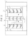
- FIG. 2 In FIG. 2 are shown both pairs of movable bearing walls 10a and 10b moved away from the pair of fixed bearing walls 1d.
- the inking means 6a and 6b are now all carried to their retracted positions away from the plate cylinders 4a and 4b of the printing units 2a-2d.
- Spaces 12a are now created between the plate cylinders 4a and 4b and inking means 6a and 6b of all the printing units 2a-2d for accommodating a maintenance man.
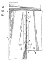
- the movable bearing walls 10a and 10b are each provided with a pair of shoes 16, FIGS. 3-5, of antifriction material on its bottom edge.
- each pair of shoes 16 are slidably mounted astride a rectilinear guide rail 17 on the platform 1a.
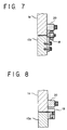
- a pair of rollers 18 are mounted to the top edge of each of the movable bearing walls 10a and 10b in horizontally spaced positions thereon, for rotation about horizontal axes at right angles with the traveling direction of that wall.
- the pair of rollers 18 on each movable wall make rolling engagement with the underside of a guide rail 20 fastened overhangingly to one associated tie beam 1e or 1f.
- another pair of rollers 19 are mounted to the top edge of each of the movable bearing walls 10a and 10b in horizontally spaced positions thereon, these for rotation about vertical axes.
- the pair of rollers 19 on each movable wall make rolling engagement with the inside surface of one associated tie beam 1e or If.
- the two pairs of movable bearing walls 10a and 10b are both provided with manual drives 14a or 14b, respectively, thereby to be moved manually between the working positions of FIG. 1 and the retracted positions of FIG. 2. Since the two manual drives 14a and 14b are of like construction except for their opposite orientations, only the manual drive 14a for the first pair of movable bearing walls 10a will be described in detail, with the understanding that the same description substantially applies to the other drive 14b.
- the representative manual drive 14a comprises a rack 23 laid on the platform 1a, and a pinion 22 in positive engagement with the rack.
- the pinion 22 is mounted fast on a pinion shaft 21 rotatably mounted to the pair of bearing walls 10a.
- An endless chain 26 extends between a sprocket 25a on the pinion shaft 21 and another sprocket 25b on a handwheel shaft 24 which also is rotatably mounted to the pair of movable bearing walls 10a.
- a handwheel 27 is mounted fast to the handwheel shaft 24.
- the instant invention further features two pairs of locking mechanisms 15a, FIG. 3, acting between the pair of fixed bearing walls 1d and the first pair of movable bearing walls 10a, and another two pairs of locking mechanisms 15b acting between the pair of fixed bearing walls 1d and the second pair of movable bearing walls 10b, for retaining the two pairs of movable bearing walls in their working positions against the risk of backing away therefrom during printing.
- Two locking mechanisms 15a are provided in vertically spaced positions for each of the first pair of movable bearing walls 10a, and two locking mechanisms 15b in vertically spaced positions for each of the second pair of movable bearing walls 10b. Since all these locking mechanisms are substantially of identical design, only one of them, 15a, the upper one of the two such mechanisms for one bearing wall 10a, will be described in detail, it being understood that the same description substantially applies to each of all the other locking mechanisms.
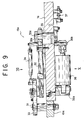
- the representative locking mechanism 15a comprises a lockpin 31 mounted fast to the movable bearing wall 10a, and a hook 33 pivotally mounted to a carriage 32 for movement into and out of locking engagement with the lockpin 31.
- a linear actuator such as a pneumatic cylinder 34 is connected between carriage 32 and hook 33 for actuating the latter.
- the hook 33 will turn clockwise, as viewed in FIG. 11, into locking engagement with the lockpin 31 upon extension of the cylinder 34, and counterclockwise out of engagement therewith upon contraction of the cylinder.
- the carriage 32 is constrained to linear travel relative to that wall in the direction of movement of the movable bearing wall 10a toward and away from the fixed bearing wall 1d.
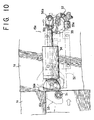
- a torque-amplifying camshaft 35 and a linear actuator such as a hydraulic cylinder 36 are employed for such travel of the carriage 32.
- the camshaft 35 rotatably extends through the fixed bearing wall 1d and has a cam 35a projecting eccentrically from one end thereof.
- the eccentric cam 35a is engaged with the carriage 32 for causing the same to travel toward and away from the lockpin 31 with the bidirectional rotation of the camshaft 35. Since the cam 35a travels arcuately, the carriage 32 receives the cam in its slot 32a which is elongated vertically, taking up the vertical component of the cam motion and utilizing its horizontal component for displacement toward and away from the lockpin 31.
- the other end of the camshaft 35 is flanged and pin-joined at 36b to one end of the hydraulic cylinder 36, the other end of which is pivotally supported at 36a on the fixed bearing wall 1d.
- the extension of the hydraulic cylinder 36 is the power stroke, causing the camshaft 35 to turn clockwise as viewed in FIG. 10.
- the clockwise turn of the camshaft results in turn in the travel of the carriage 32 away from the lockpin 31.
- An adjustable stop is provided at 37 on the fixed bearing wall 1d for limiting the power stroke of the cylinder 36.
- the two pairs of movable bearing walls 10a and 10b are to be held against the pair of fixed bearing walls 1d, as pictured in FIG. 1, for printing.
- the pairs of movable bearing walls 10a and 10b may be driven into contact with the pair of fixed bearing walls 1d by turning the two handwheels 27 on the platform 1a. No great force will be required for turning the handwheels 27 as the movable bearing walls 10a and 10b ride over the guide rails 17, FIGS. 4 and 5, via the antifriction shoes 16.
- these movable bearing walls have their top edges guided both vertically and transversely via the rollers 18 and 19, as in FIGS. 7 and 8, they will travel all the more smoothly.
- the pneumatic cylinders 34, FIGS. 9-11, of all the locking mechanisms 15a and 15b may be extended for pivoting the hooks 33 into locking engagement with the lockpins 31.
- the hydraulic cylinders 36 on the fixed bearing walls 1d may be extended for moving the carriages 32 away from the lockpins 31, thereby causing the hooks 33 to pull the pairs of movable bearing walls 10a and 10b into forced contact with the pair of fixed bearing walls.
- the final inking rollers 5, FIG. 1, of the inking means 6a and 6b of all the printing units 2a-2d have been brought into proper engagement with the plate cylinders 4a and 4b, making the machine ready for printing.
- the two pairs of movable bearing walls 10a and 10b may be unlocked from the pair of fixed bearing walls 1d by the reversal of the foregoing procedure. Then the handwheels 27 may be turned for backing the movable bearing walls 10a and 10b from their FIG. 1 to FIG. 2 positions, creating the spaces 12a between the inking means 6a and 6b and the plate cylinders 4a and 4b. By entering these spaces 12a the maintenance man can gain full access to the plate cylinders 4a and 4b and the final inking rollers 5 of the inking means 6a and 6b, in particular, for easy servicing.
Landscapes
- Engineering & Computer Science (AREA)
- Mechanical Engineering (AREA)
- Rotary Presses (AREA)
- Inking, Control Or Cleaning Of Printing Machines (AREA)
Abstract
Description
and a
Claims (7)
- An easy-to-maintenance, roll-fed, offset perfecting printing press comprising a plurality of offset perfecting printing units (2a, 2b, 2c, 2d) stacked up one upon another for printing both sides of a continuous web (7) of paper or like material, each unit comprising a first and a second blanket cylinder (3a, 3b) held against each other, a first and a second plate cylinder (4a, 4b) held respectively against the first and the second blanket cylinder, and first and second inking means (6a, 6b) for inking the first and the second plate cylinder, respectively, characterized in that the first and the second blanket cylinder (3a, 3b), and the first and the second plate cylinder (4a, 4b), of all the printing units (2a-2d) are rotatably supported by and between a pair of fixed bearing walls (1d) which are immovably mounted to a framework (1), that the first ink ing means (6a) of all the printing units (2a-2d) are operably supported by and between a first pair of movable bearing walls (10a) which are mounted to the framework (1) for movement toward and away from the pair of fixed bearing walls (1d) between a working position, where the first inking means (6a) of all the printing units (2a-2d) are held against the first plate cylinders (4a) thereof, and a retracted position where the first inking means (6a) of all the printing units (2a-2b) are held away from the first plate cylinders (4a) thereof for providing a space (12a) for accommodating maintenance personnel, that the second inking means (6b) of all the printing units (2a-2b) are operably supported by and between a second pair of movable bearing walls (10b) which are mounted to the framework (1) for movement toward and away from the pair of fixed bearing walls (1d) between a working position, where the second inking means (6b) of all the printing units (2a-2d) are held against the second plate cylinders (4b) thereof, and a retracted position where the second inking means (6b) of all the printing units (2a-2d) are held away from the second plate cylinders (4b) thereof for providing a space (12a) for accommodating maintenance personnel, and that locking means (15a, 15b) act between the first pair of movable bearing walls (10a) and the framework (1), and between the second pair of movable bearing walls (10b) and the framework (1), for firmly retaining the first and the second pair of movable bearing walls (10a, 10b) in their working positions.
- An easy-to-maintenance, roll-fed, offset perfecting printing press as claimed in claim 1, characterized in that the locking means (15a, 15b) comprises a plurality of lockpins (31) formed at least one on each of the first and the second pair of movable bearing walls (10a, 10b), a plurality of carriages (32) mounted to the framework (1) and disposed one adjacent each lockpin, each carriage being movable relative to the framework in a direction of movement of each movable bearing wall toward and away from one fixed bearing wall (1d), a hook (33) mounted to each carriage for movement relative to the carriage into and out of locking engagement with one lockpin (31), and actuator means (35, 36) acting between the framework and each carriage for forcing the latter in such a direction that one associated movable bearing wall, having the lockpin thereon engaged by the hook on the carriage, is urged against the framework.
- An easy-to-maintenance, roll-fed, offset perfecting printing press as claimed in claim 2, characterized in that the actuator means of the locking means (15a, 15b) comprises a camshaft (35) rotatably mounted to the framework and operatively engaged with each carriage (32)in such a way that the carriage linearly travels back and forth relative to the framework with bidirectional rotation of the camshaft, and a linear actuator (36) mounted to the framework and operatively coupled to each camshaft for causing bidirectional rotation thereof.
- An easy-to-maintenance, roll-fed, offset perfecting printing press as claimed in claim 3, characterized in that the linear actuator (36) is operatively coupled to the camshaft (35) at an eccentric point on the latter, that the camshaft has a cam (35a) formed eccentrically thereon and slidably engaged in a slot (32a) in the carriage, and that the eccentric point at which the linear actuator is coupled to the camshaft is spaced a greater distance from the axis of rotation of the camshaft than the eccentric cam is.
- An easy-to-maintenance, roll-fed, offset perfecting printing press as claimed in claim 2, characterized in that the hook (33) of the locking means is pivotable on each carriage (32) for movement into and out of locking engagement with one associated lockpin (31), and that the locking means further comprises a linear actuator (34) acting between each carriage and the hook thereon for pivoting the latter into and out of locking engagement with one associated lockpin.
- An easy-to-maintenance, roll-fed, offset perfecting printing press as claimed in claim 1, characterized in that drive means (14a, 14b) are provided for moving each pair of movable bearing walls (10a, 10b) between the working and the retracted position thereof.
- An easy-to-maintenance, roll-fed, offset perfecting printing press as claimed in claim 6, characterized in that the drive means (14a, 14b) comprises a rack (23) extending along the path of each pair of movable bearing walls (10a, 10b) between the working and the retracted position thereof, a pinion (22) rotatably mounted to each pair of movable bearing walls and engaged with one associated rack, and means (27, 25a, 25b, 26) for imparting rotation to each pinion.
Applications Claiming Priority (2)
| Application Number | Priority Date | Filing Date | Title |
|---|---|---|---|
| JP2000127092A JP2001310440A (en) | 2000-04-27 | 2000-04-27 | Tower-type offset rotary press |
| JP2000127092 | 2000-04-27 |
Publications (2)
| Publication Number | Publication Date |
|---|---|
| EP1149694A1 true EP1149694A1 (en) | 2001-10-31 |
| EP1149694B1 EP1149694B1 (en) | 2006-04-19 |
Family
ID=18636751
Family Applications (1)
| Application Number | Title | Priority Date | Filing Date |
|---|---|---|---|
| EP01108915A Expired - Lifetime EP1149694B1 (en) | 2000-04-27 | 2001-04-10 | Easy-of-maintenance printing press having a stack of offset perfecting printing units |
Country Status (4)
| Country | Link |
|---|---|
| US (1) | US20010037743A1 (en) |
| EP (1) | EP1149694B1 (en) |
| JP (1) | JP2001310440A (en) |
| DE (1) | DE60118828T2 (en) |
Cited By (19)
| Publication number | Priority date | Publication date | Assignee | Title |
|---|---|---|---|---|
| DE10209216A1 (en) * | 2002-03-04 | 2003-09-25 | Koenig & Bauer Ag | Printing machine of plate and impression cylinders has plate cylinders facing across web U-path and alternately addressed to and set off from web using adjustable printing gaps. |
| WO2005005149A3 (en) * | 2003-07-08 | 2005-03-24 | Goss Graphic Systems Ltd | Printing press |
| WO2005037553A1 (en) | 2003-10-14 | 2005-04-28 | Koenig & Bauer Aktiengesellschaft | Movable frame parts in a printing press |
| WO2005037552A1 (en) * | 2003-10-14 | 2005-04-28 | Koenig & Bauer Aktiengesellschaft | Printing units, and method for moving a frame part |
| WO2004110759A3 (en) * | 2003-06-09 | 2005-06-09 | Goss International Inc | Offset printing press with cantilevered printing and inking modules |
| WO2005115756A1 (en) | 2004-04-28 | 2005-12-08 | Koenig & Bauer Aktiengesellschaft | Printing unit pertaining to a multi-colour roller rotary press, and method for operating the same |
| WO2005097503A3 (en) * | 2004-04-05 | 2006-04-20 | Koenig & Bauer Ag | Drives for a printing unit |
| DE102006002331B3 (en) * | 2006-01-18 | 2006-12-21 | Koenig & Bauer Ag | Offset printing press, with a number of frame sections, uses underpressure to hold the frames together with a variable gap between them |
| WO2007017295A1 (en) * | 2005-08-04 | 2007-02-15 | Goss Graphic Systems Limited | Printing press |
| GB2403688B (en) * | 2003-07-08 | 2007-02-21 | Goss Graphic Systems Ltd | Printing press |
| EP2047989A1 (en) | 2007-10-12 | 2009-04-15 | Koenig & Bauer AG | Printing unit with at least two side adjustment parts whose separation can be adjusted horizontally relative to each other |
| WO2009049935A1 (en) * | 2007-10-12 | 2009-04-23 | Koenig & Bauer Aktiengesellschaft | Printing unit comprising at least two side frame parts whose distance relative to each other can be modified in a horizontal direction |
| WO2009049936A1 (en) | 2007-10-12 | 2009-04-23 | Koenig & Bauer Aktiengesellschaft | Printing unit having at least two lateral frame parts the distance of which can be changed relative to each other in a horizontal direction |
| EP1997628A3 (en) * | 2007-05-30 | 2011-07-13 | manroland AG | Printing unit of a printing press |
| EP2036722A3 (en) * | 2007-09-14 | 2011-07-27 | manroland AG | Printing unit in a rotary cylinder printing press |
| EP2036723A3 (en) * | 2007-09-14 | 2011-07-27 | manroland AG | Printing unit in a web-fed rotary printing press |
| US8051774B2 (en) | 2004-04-29 | 2011-11-08 | Goss Graphic Systems Limited | Printing plate module, printing press, and method of mounting plates |
| US8550000B2 (en) | 2005-05-09 | 2013-10-08 | Goss Graphic Systems Limited | Printing plate unloading apparatus and method |
| CN103465607A (en) * | 2013-08-30 | 2013-12-25 | 高斯图文印刷系统(中国)有限公司 | Web offset press |
Families Citing this family (3)
| Publication number | Priority date | Publication date | Assignee | Title |
|---|---|---|---|---|
| US6684775B2 (en) * | 2001-06-07 | 2004-02-03 | Heidelberger Druckmaschinen Ag | Printing unit with roll-away inkers |
| CN100386198C (en) * | 2004-11-26 | 2008-05-07 | 李新忠 | Satellite flexible-plate printer |
| DE102008041842B4 (en) * | 2008-09-05 | 2012-03-22 | Koenig & Bauer Aktiengesellschaft | Printing unit of a printing press with at least two relatively mutually positionally adjustable frame parts |
Citations (6)
| Publication number | Priority date | Publication date | Assignee | Title |
|---|---|---|---|---|
| US2557381A (en) * | 1946-08-09 | 1951-06-19 | William C Huebner | Multiple unit printing press |
| US3041966A (en) * | 1959-09-24 | 1962-07-03 | Hoe & Co R | Multicolor web offset press |
| DE2234089A1 (en) * | 1972-07-08 | 1974-01-17 | Hinniger Automatic Druckmasch | ROTARY PRINTING MACHINE |
| EP0444225A1 (en) * | 1990-02-27 | 1991-09-04 | Komori Corporation | Movable inker type printing machine |
| EP0459595A1 (en) * | 1986-05-14 | 1991-12-04 | Strachan Henshaw Machinery Limited | Processing paper and other webs |
| WO1995024313A1 (en) * | 1994-03-10 | 1995-09-14 | Koenig & Bauer-Albert Aktiengesellschaft | Printing group for a colour-printing web-fed rotary press |
Family Cites Families (1)
| Publication number | Priority date | Publication date | Assignee | Title |
|---|---|---|---|---|
| JP2567038B2 (en) * | 1988-06-09 | 1996-12-25 | 株式会社小森コーポレーション | Printing machine with an automatic lift |
-
2000
- 2000-04-27 JP JP2000127092A patent/JP2001310440A/en active Pending
-
2001
- 2001-04-04 US US09/824,645 patent/US20010037743A1/en not_active Abandoned
- 2001-04-10 DE DE60118828T patent/DE60118828T2/en not_active Expired - Lifetime
- 2001-04-10 EP EP01108915A patent/EP1149694B1/en not_active Expired - Lifetime
Patent Citations (6)
| Publication number | Priority date | Publication date | Assignee | Title |
|---|---|---|---|---|
| US2557381A (en) * | 1946-08-09 | 1951-06-19 | William C Huebner | Multiple unit printing press |
| US3041966A (en) * | 1959-09-24 | 1962-07-03 | Hoe & Co R | Multicolor web offset press |
| DE2234089A1 (en) * | 1972-07-08 | 1974-01-17 | Hinniger Automatic Druckmasch | ROTARY PRINTING MACHINE |
| EP0459595A1 (en) * | 1986-05-14 | 1991-12-04 | Strachan Henshaw Machinery Limited | Processing paper and other webs |
| EP0444225A1 (en) * | 1990-02-27 | 1991-09-04 | Komori Corporation | Movable inker type printing machine |
| WO1995024313A1 (en) * | 1994-03-10 | 1995-09-14 | Koenig & Bauer-Albert Aktiengesellschaft | Printing group for a colour-printing web-fed rotary press |
Cited By (37)
| Publication number | Priority date | Publication date | Assignee | Title |
|---|---|---|---|---|
| DE10209216A1 (en) * | 2002-03-04 | 2003-09-25 | Koenig & Bauer Ag | Printing machine of plate and impression cylinders has plate cylinders facing across web U-path and alternately addressed to and set off from web using adjustable printing gaps. |
| DE10209216B4 (en) * | 2002-03-04 | 2005-04-28 | Koenig & Bauer Ag | press |
| WO2004110759A3 (en) * | 2003-06-09 | 2005-06-09 | Goss International Inc | Offset printing press with cantilevered printing and inking modules |
| US7373880B2 (en) | 2003-06-09 | 2008-05-20 | Goss International Corporation | Variable format offset printing press |
| US7171900B2 (en) | 2003-06-09 | 2007-02-06 | Goss International Corporation | Variable format offset printing machine |
| GB2403688B (en) * | 2003-07-08 | 2007-02-21 | Goss Graphic Systems Ltd | Printing press |
| CN100404251C (en) * | 2003-07-08 | 2008-07-23 | 戈斯印刷系统有限公司 | Printing machine |
| WO2005005149A3 (en) * | 2003-07-08 | 2005-03-24 | Goss Graphic Systems Ltd | Printing press |
| WO2005037553A1 (en) | 2003-10-14 | 2005-04-28 | Koenig & Bauer Aktiengesellschaft | Movable frame parts in a printing press |
| WO2005037552A1 (en) * | 2003-10-14 | 2005-04-28 | Koenig & Bauer Aktiengesellschaft | Printing units, and method for moving a frame part |
| US7707936B2 (en) | 2003-10-14 | 2010-05-04 | Koenig & Bauer Aktiengesellschaft | Movable frame parts in a printing press |
| CN100464977C (en) * | 2003-10-14 | 2009-03-04 | 柯尼格及包尔公开股份有限公司 | Printing unit and method for moving frame sections |
| DE10347571B4 (en) * | 2003-10-14 | 2008-09-18 | Koenig & Bauer Aktiengesellschaft | printing unit |
| DE10347571A1 (en) * | 2003-10-14 | 2005-05-19 | Koenig & Bauer Ag | printing unit |
| WO2005097503A3 (en) * | 2004-04-05 | 2006-04-20 | Koenig & Bauer Ag | Drives for a printing unit |
| EP1767356A2 (en) | 2004-04-28 | 2007-03-28 | Koenig & Bauer Aktiengesellschaft | Printing units pertaining to a multi-colour roller rotary press, and method for operating the same. |
| US7735418B2 (en) | 2004-04-28 | 2010-06-15 | Koenig & Bauer Aktiengesellschaft | Printing unit pertaining to a multi-color roller rotary press, and method for operating the same |
| WO2005115756A1 (en) | 2004-04-28 | 2005-12-08 | Koenig & Bauer Aktiengesellschaft | Printing unit pertaining to a multi-colour roller rotary press, and method for operating the same |
| US8505452B2 (en) | 2004-04-29 | 2013-08-13 | Goss Graphic Systems Limited | Printing press including plate support member and plate loading module |
| US8051774B2 (en) | 2004-04-29 | 2011-11-08 | Goss Graphic Systems Limited | Printing plate module, printing press, and method of mounting plates |
| US8550000B2 (en) | 2005-05-09 | 2013-10-08 | Goss Graphic Systems Limited | Printing plate unloading apparatus and method |
| CN101198472B (en) * | 2005-08-04 | 2013-06-19 | 高斯绘图系统有限公司 | Printing unit and its control method |
| WO2007017295A1 (en) * | 2005-08-04 | 2007-02-15 | Goss Graphic Systems Limited | Printing press |
| DE102006002331B3 (en) * | 2006-01-18 | 2006-12-21 | Koenig & Bauer Ag | Offset printing press, with a number of frame sections, uses underpressure to hold the frames together with a variable gap between them |
| EP1997628A3 (en) * | 2007-05-30 | 2011-07-13 | manroland AG | Printing unit of a printing press |
| EP2036722A3 (en) * | 2007-09-14 | 2011-07-27 | manroland AG | Printing unit in a rotary cylinder printing press |
| EP2036723A3 (en) * | 2007-09-14 | 2011-07-27 | manroland AG | Printing unit in a web-fed rotary printing press |
| US7926420B2 (en) | 2007-10-12 | 2011-04-19 | Koenig & Bauer Atkiengesellschaft | Printing unit having at least two lateral frame parts the distance of which can be changed relative to each other in a horizontal direction |
| US7886664B2 (en) | 2007-10-12 | 2011-02-15 | Koenig & Bauer Aktiengesellschaft | Printing unit comprising at least two side frame parts whose distance relative to each other can be modified in a horizontal direction |
| WO2009049937A1 (en) * | 2007-10-12 | 2009-04-23 | Koenig & Bauer Aktiengesellschaft | Printing unit having at least two lateral frame parts the distance of which can be changed relative to each other in a horizontal direction |
| CN101821098B (en) * | 2007-10-12 | 2012-07-25 | 柯尼格及包尔公开股份有限公司 | Printing unit having at least two side frame sections with variable horizontal spacing relative to each other |
| CN101821100B (en) * | 2007-10-12 | 2012-11-07 | 柯尼格及包尔公开股份有限公司 | Printing unit having at least two lateral frame parts the distance of which can be changed relative to each other in horizontal direction |
| WO2009049936A1 (en) | 2007-10-12 | 2009-04-23 | Koenig & Bauer Aktiengesellschaft | Printing unit having at least two lateral frame parts the distance of which can be changed relative to each other in a horizontal direction |
| WO2009049935A1 (en) * | 2007-10-12 | 2009-04-23 | Koenig & Bauer Aktiengesellschaft | Printing unit comprising at least two side frame parts whose distance relative to each other can be modified in a horizontal direction |
| EP2047989A1 (en) | 2007-10-12 | 2009-04-15 | Koenig & Bauer AG | Printing unit with at least two side adjustment parts whose separation can be adjusted horizontally relative to each other |
| CN103465607A (en) * | 2013-08-30 | 2013-12-25 | 高斯图文印刷系统(中国)有限公司 | Web offset press |
| CN103465607B (en) * | 2013-08-30 | 2016-06-29 | 高斯图文印刷系统(中国)有限公司 | A kind of roll-fed offset printing press |
Also Published As
| Publication number | Publication date |
|---|---|
| JP2001310440A (en) | 2001-11-06 |
| DE60118828D1 (en) | 2006-05-24 |
| DE60118828T2 (en) | 2006-09-28 |
| EP1149694B1 (en) | 2006-04-19 |
| US20010037743A1 (en) | 2001-11-08 |
Similar Documents
| Publication | Publication Date | Title |
|---|---|---|
| EP1149694B1 (en) | Easy-of-maintenance printing press having a stack of offset perfecting printing units | |
| US6684775B2 (en) | Printing unit with roll-away inkers | |
| CN1081986C (en) | Printing systems for multi-color web presses | |
| CN1325252C (en) | Printing machine by intaglio engraving | |
| DE3326067A1 (en) | Mould-changing apparatus | |
| JPH051398Y2 (en) | ||
| US7707936B2 (en) | Movable frame parts in a printing press | |
| KR100882136B1 (en) | Continuous printing machine for steel plate | |
| CN101879810B (en) | Poker printing system with gravure printing and flexo printing combination | |
| DE3313219C2 (en) | Printing unit for a rotary printing press | |
| CN210680015U (en) | Relief printing device | |
| DE102016206840B4 (en) | Printing unit of a printing machine that prints a sheet-shaped substrate | |
| US4485659A (en) | Apparatus for adjustably locking the movable counter gripping head of a sheet or section stretcher | |
| CN1778555A (en) | Satellite flexible-plate printer | |
| DE2943894A1 (en) | Paper transport suction cylinder - is intermittently driven and acts as pressure cylinder under plate of screen printer | |
| ITMI992668A1 (en) | DEVICE FOR ROUNDING THE BACK OF BOOK BLOCKS IN BINDING MACHINE | |
| CN211138449U (en) | Rotary flexible printing press | |
| JP2511507Y2 (en) | Side guide device | |
| CN217803804U (en) | Flexible printing device for printed matter | |
| DK141279B (en) | PRESSURE DEVICE AND INDIRECT PRESSURE | |
| CN212171592U (en) | A clutch mechanism of a printing press embossing device | |
| CN214055536U (en) | Movable trimming waste discharge machine | |
| DE82134C (en) | ||
| DE50115819D1 (en) | Device for imaging cylindrical surfaces in printing machines | |
| ITMI20000080A1 (en) | PRESSING MACHINES TO PRESS BOOK BLOCKS KEPT IN THE AREA NEAR THE BACK BY MEANS OF A CROSSING OR PRESSING BEAM |
Legal Events
| Date | Code | Title | Description |
|---|---|---|---|
| PUAI | Public reference made under article 153(3) epc to a published international application that has entered the european phase |
Free format text: ORIGINAL CODE: 0009012 |
|
| AK | Designated contracting states |
Kind code of ref document: A1 Designated state(s): AT BE CH CY DE DK ES FI FR GB GR IE IT LI LU MC NL PT SE TR Kind code of ref document: A1 Designated state(s): DE GB NL |
|
| AX | Request for extension of the european patent |
Free format text: AL;LT;LV;MK;RO;SI |
|
| 17P | Request for examination filed |
Effective date: 20011116 |
|
| AKX | Designation fees paid |
Free format text: DE GB NL |
|
| 17Q | First examination report despatched |
Effective date: 20021001 |
|
| GRAP | Despatch of communication of intention to grant a patent |
Free format text: ORIGINAL CODE: EPIDOSNIGR1 |
|
| RIN1 | Information on inventor provided before grant (corrected) |
Inventor name: TAKAHASHI, KENJI |
|
| GRAS | Grant fee paid |
Free format text: ORIGINAL CODE: EPIDOSNIGR3 |
|
| GRAA | (expected) grant |
Free format text: ORIGINAL CODE: 0009210 |
|
| AK | Designated contracting states |
Kind code of ref document: B1 Designated state(s): DE GB NL |
|
| REG | Reference to a national code |
Ref country code: GB Ref legal event code: FG4D |
|
| REF | Corresponds to: |
Ref document number: 60118828 Country of ref document: DE Date of ref document: 20060524 Kind code of ref document: P |
|
| PLBE | No opposition filed within time limit |
Free format text: ORIGINAL CODE: 0009261 |
|
| STAA | Information on the status of an ep patent application or granted ep patent |
Free format text: STATUS: NO OPPOSITION FILED WITHIN TIME LIMIT |
|
| 26N | No opposition filed |
Effective date: 20070122 |
|
| PGFP | Annual fee paid to national office [announced via postgrant information from national office to epo] |
Ref country code: NL Payment date: 20180423 Year of fee payment: 18 |
|
| PGFP | Annual fee paid to national office [announced via postgrant information from national office to epo] |
Ref country code: GB Payment date: 20180403 Year of fee payment: 18 |
|
| PGFP | Annual fee paid to national office [announced via postgrant information from national office to epo] |
Ref country code: DE Payment date: 20190418 Year of fee payment: 19 |
|
| REG | Reference to a national code |
Ref country code: NL Ref legal event code: MM Effective date: 20190501 |
|
| GBPC | Gb: european patent ceased through non-payment of renewal fee |
Effective date: 20190410 |
|
| PG25 | Lapsed in a contracting state [announced via postgrant information from national office to epo] |
Ref country code: NL Free format text: LAPSE BECAUSE OF NON-PAYMENT OF DUE FEES Effective date: 20190501 Ref country code: GB Free format text: LAPSE BECAUSE OF NON-PAYMENT OF DUE FEES Effective date: 20190410 |
|
| REG | Reference to a national code |
Ref country code: DE Ref legal event code: R119 Ref document number: 60118828 Country of ref document: DE |
|
| PG25 | Lapsed in a contracting state [announced via postgrant information from national office to epo] |
Ref country code: DE Free format text: LAPSE BECAUSE OF NON-PAYMENT OF DUE FEES Effective date: 20201103 |