EP1149677A2 - Verfahren und Vorrichtung zur Herstellung einer Doppelsluhhaut - Google Patents
Verfahren und Vorrichtung zur Herstellung einer Doppelsluhhaut Download PDFInfo
- Publication number
- EP1149677A2 EP1149677A2 EP01250116A EP01250116A EP1149677A2 EP 1149677 A2 EP1149677 A2 EP 1149677A2 EP 01250116 A EP01250116 A EP 01250116A EP 01250116 A EP01250116 A EP 01250116A EP 1149677 A2 EP1149677 A2 EP 1149677A2
- Authority
- EP
- European Patent Office
- Prior art keywords
- slush skin
- double slush
- double
- overpressure
- skin
- Prior art date
- Legal status (The legal status is an assumption and is not a legal conclusion. Google has not performed a legal analysis and makes no representation as to the accuracy of the status listed.)
- Withdrawn
Links
- 238000000034 method Methods 0.000 title claims abstract description 69
- 239000004033 plastic Substances 0.000 claims abstract description 69
- 238000004519 manufacturing process Methods 0.000 claims abstract description 45
- 230000008569 process Effects 0.000 claims abstract description 44
- 230000015572 biosynthetic process Effects 0.000 claims abstract description 13
- 239000000463 material Substances 0.000 claims description 37
- 230000000712 assembly Effects 0.000 claims description 26
- 238000000429 assembly Methods 0.000 claims description 26
- 238000000465 moulding Methods 0.000 claims description 22
- 239000003795 chemical substances by application Substances 0.000 claims description 17
- 238000005187 foaming Methods 0.000 claims description 15
- 238000005323 electroforming Methods 0.000 claims description 14
- PXHVJJICTQNCMI-UHFFFAOYSA-N Nickel Chemical compound [Ni] PXHVJJICTQNCMI-UHFFFAOYSA-N 0.000 claims description 13
- 229910001220 stainless steel Inorganic materials 0.000 claims description 9
- 239000010935 stainless steel Substances 0.000 claims description 9
- 239000003351 stiffener Substances 0.000 claims description 8
- 230000005226 mechanical processes and functions Effects 0.000 claims description 6
- 229910052759 nickel Inorganic materials 0.000 claims description 6
- XAGFODPZIPBFFR-UHFFFAOYSA-N aluminium Chemical compound [Al] XAGFODPZIPBFFR-UHFFFAOYSA-N 0.000 claims description 4
- 229910052782 aluminium Inorganic materials 0.000 claims description 4
- 229920003002 synthetic resin Polymers 0.000 claims description 4
- 239000000057 synthetic resin Substances 0.000 claims description 4
- 238000003466 welding Methods 0.000 claims description 4
- 229910000831 Steel Inorganic materials 0.000 claims description 3
- 239000010959 steel Substances 0.000 claims description 3
- XLYOFNOQVPJJNP-UHFFFAOYSA-N water Substances O XLYOFNOQVPJJNP-UHFFFAOYSA-N 0.000 claims description 2
- 238000007493 shaping process Methods 0.000 claims 4
- 229910003460 diamond Inorganic materials 0.000 claims 1
- 239000010432 diamond Substances 0.000 claims 1
- 239000000843 powder Substances 0.000 description 11
- 239000004604 Blowing Agent Substances 0.000 description 8
- 239000002131 composite material Substances 0.000 description 6
- 229920000642 polymer Polymers 0.000 description 6
- 238000012937 correction Methods 0.000 description 5
- 238000009826 distribution Methods 0.000 description 4
- 238000009713 electroplating Methods 0.000 description 4
- 238000005496 tempering Methods 0.000 description 4
- 238000005452 bending Methods 0.000 description 3
- 238000004026 adhesive bonding Methods 0.000 description 2
- 239000000969 carrier Substances 0.000 description 2
- 238000001816 cooling Methods 0.000 description 2
- 238000005520 cutting process Methods 0.000 description 2
- 239000006260 foam Substances 0.000 description 2
- 230000009467 reduction Effects 0.000 description 2
- 238000009827 uniform distribution Methods 0.000 description 2
- 239000000853 adhesive Substances 0.000 description 1
- 230000001070 adhesive effect Effects 0.000 description 1
- 230000008901 benefit Effects 0.000 description 1
- 230000008859 change Effects 0.000 description 1
- 239000011248 coating agent Substances 0.000 description 1
- 238000000576 coating method Methods 0.000 description 1
- 238000010276 construction Methods 0.000 description 1
- 239000002826 coolant Substances 0.000 description 1
- 230000006735 deficit Effects 0.000 description 1
- 238000011038 discontinuous diafiltration by volume reduction Methods 0.000 description 1
- 230000000694 effects Effects 0.000 description 1
- 238000005516 engineering process Methods 0.000 description 1
- 238000005246 galvanizing Methods 0.000 description 1
- PXHVJJICTQNCMI-OUBTZVSYSA-N nickel-60 atom Chemical compound [60Ni] PXHVJJICTQNCMI-OUBTZVSYSA-N 0.000 description 1
- 238000007747 plating Methods 0.000 description 1
- 238000003825 pressing Methods 0.000 description 1
- 239000003380 propellant Substances 0.000 description 1
- 239000002994 raw material Substances 0.000 description 1
- 238000004904 shortening Methods 0.000 description 1
- 239000007858 starting material Substances 0.000 description 1
Images



Classifications
-
- B—PERFORMING OPERATIONS; TRANSPORTING
- B29—WORKING OF PLASTICS; WORKING OF SUBSTANCES IN A PLASTIC STATE IN GENERAL
- B29C—SHAPING OR JOINING OF PLASTICS; SHAPING OF MATERIAL IN A PLASTIC STATE, NOT OTHERWISE PROVIDED FOR; AFTER-TREATMENT OF THE SHAPED PRODUCTS, e.g. REPAIRING
- B29C41/00—Shaping by coating a mould, core or other substrate, i.e. by depositing material and stripping-off the shaped article; Apparatus therefor
- B29C41/02—Shaping by coating a mould, core or other substrate, i.e. by depositing material and stripping-off the shaped article; Apparatus therefor for making articles of definite length, i.e. discrete articles
- B29C41/18—Slush casting, i.e. pouring moulding material into a hollow mould with excess material being poured off
-
- B—PERFORMING OPERATIONS; TRANSPORTING
- B29—WORKING OF PLASTICS; WORKING OF SUBSTANCES IN A PLASTIC STATE IN GENERAL
- B29C—SHAPING OR JOINING OF PLASTICS; SHAPING OF MATERIAL IN A PLASTIC STATE, NOT OTHERWISE PROVIDED FOR; AFTER-TREATMENT OF THE SHAPED PRODUCTS, e.g. REPAIRING
- B29C33/00—Moulds or cores; Details thereof or accessories therefor
- B29C33/02—Moulds or cores; Details thereof or accessories therefor with incorporated heating or cooling means
- B29C33/04—Moulds or cores; Details thereof or accessories therefor with incorporated heating or cooling means using liquids, gas or steam
-
- B—PERFORMING OPERATIONS; TRANSPORTING
- B29—WORKING OF PLASTICS; WORKING OF SUBSTANCES IN A PLASTIC STATE IN GENERAL
- B29C—SHAPING OR JOINING OF PLASTICS; SHAPING OF MATERIAL IN A PLASTIC STATE, NOT OTHERWISE PROVIDED FOR; AFTER-TREATMENT OF THE SHAPED PRODUCTS, e.g. REPAIRING
- B29C33/00—Moulds or cores; Details thereof or accessories therefor
- B29C33/38—Moulds or cores; Details thereof or accessories therefor characterised by the material or the manufacturing process
-
- B—PERFORMING OPERATIONS; TRANSPORTING
- B29—WORKING OF PLASTICS; WORKING OF SUBSTANCES IN A PLASTIC STATE IN GENERAL
- B29C—SHAPING OR JOINING OF PLASTICS; SHAPING OF MATERIAL IN A PLASTIC STATE, NOT OTHERWISE PROVIDED FOR; AFTER-TREATMENT OF THE SHAPED PRODUCTS, e.g. REPAIRING
- B29C33/00—Moulds or cores; Details thereof or accessories therefor
- B29C33/44—Moulds or cores; Details thereof or accessories therefor with means for, or specially constructed to facilitate, the removal of articles, e.g. of undercut articles
- B29C33/46—Moulds or cores; Details thereof or accessories therefor with means for, or specially constructed to facilitate, the removal of articles, e.g. of undercut articles using fluid pressure
-
- B—PERFORMING OPERATIONS; TRANSPORTING
- B29—WORKING OF PLASTICS; WORKING OF SUBSTANCES IN A PLASTIC STATE IN GENERAL
- B29C—SHAPING OR JOINING OF PLASTICS; SHAPING OF MATERIAL IN A PLASTIC STATE, NOT OTHERWISE PROVIDED FOR; AFTER-TREATMENT OF THE SHAPED PRODUCTS, e.g. REPAIRING
- B29C41/00—Shaping by coating a mould, core or other substrate, i.e. by depositing material and stripping-off the shaped article; Apparatus therefor
- B29C41/02—Shaping by coating a mould, core or other substrate, i.e. by depositing material and stripping-off the shaped article; Apparatus therefor for making articles of definite length, i.e. discrete articles
- B29C41/22—Making multilayered or multicoloured articles
-
- B—PERFORMING OPERATIONS; TRANSPORTING
- B29—WORKING OF PLASTICS; WORKING OF SUBSTANCES IN A PLASTIC STATE IN GENERAL
- B29C—SHAPING OR JOINING OF PLASTICS; SHAPING OF MATERIAL IN A PLASTIC STATE, NOT OTHERWISE PROVIDED FOR; AFTER-TREATMENT OF THE SHAPED PRODUCTS, e.g. REPAIRING
- B29C41/00—Shaping by coating a mould, core or other substrate, i.e. by depositing material and stripping-off the shaped article; Apparatus therefor
- B29C41/34—Component parts, details or accessories; Auxiliary operations
- B29C41/46—Heating or cooling
-
- B—PERFORMING OPERATIONS; TRANSPORTING
- B29—WORKING OF PLASTICS; WORKING OF SUBSTANCES IN A PLASTIC STATE IN GENERAL
- B29C—SHAPING OR JOINING OF PLASTICS; SHAPING OF MATERIAL IN A PLASTIC STATE, NOT OTHERWISE PROVIDED FOR; AFTER-TREATMENT OF THE SHAPED PRODUCTS, e.g. REPAIRING
- B29C41/00—Shaping by coating a mould, core or other substrate, i.e. by depositing material and stripping-off the shaped article; Apparatus therefor
- B29C41/34—Component parts, details or accessories; Auxiliary operations
- B29C41/52—Measuring, controlling or regulating
-
- B—PERFORMING OPERATIONS; TRANSPORTING
- B29—WORKING OF PLASTICS; WORKING OF SUBSTANCES IN A PLASTIC STATE IN GENERAL
- B29C—SHAPING OR JOINING OF PLASTICS; SHAPING OF MATERIAL IN A PLASTIC STATE, NOT OTHERWISE PROVIDED FOR; AFTER-TREATMENT OF THE SHAPED PRODUCTS, e.g. REPAIRING
- B29C43/00—Compression moulding, i.e. applying external pressure to flow the moulding material; Apparatus therefor
- B29C43/02—Compression moulding, i.e. applying external pressure to flow the moulding material; Apparatus therefor of articles of definite length, i.e. discrete articles
- B29C43/18—Compression moulding, i.e. applying external pressure to flow the moulding material; Apparatus therefor of articles of definite length, i.e. discrete articles incorporating preformed parts or layers, e.g. compression moulding around inserts or for coating articles
- B29C43/183—Compression moulding, i.e. applying external pressure to flow the moulding material; Apparatus therefor of articles of definite length, i.e. discrete articles incorporating preformed parts or layers, e.g. compression moulding around inserts or for coating articles the preformed layer being a lining, e.g. shaped in the mould before compression moulding, or a preformed shell adapted to the shape of the mould
-
- B—PERFORMING OPERATIONS; TRANSPORTING
- B29—WORKING OF PLASTICS; WORKING OF SUBSTANCES IN A PLASTIC STATE IN GENERAL
- B29C—SHAPING OR JOINING OF PLASTICS; SHAPING OF MATERIAL IN A PLASTIC STATE, NOT OTHERWISE PROVIDED FOR; AFTER-TREATMENT OF THE SHAPED PRODUCTS, e.g. REPAIRING
- B29C33/00—Moulds or cores; Details thereof or accessories therefor
- B29C33/38—Moulds or cores; Details thereof or accessories therefor characterised by the material or the manufacturing process
- B29C33/3828—Moulds made of at least two different materials having different thermal conductivities
-
- B—PERFORMING OPERATIONS; TRANSPORTING
- B29—WORKING OF PLASTICS; WORKING OF SUBSTANCES IN A PLASTIC STATE IN GENERAL
- B29C—SHAPING OR JOINING OF PLASTICS; SHAPING OF MATERIAL IN A PLASTIC STATE, NOT OTHERWISE PROVIDED FOR; AFTER-TREATMENT OF THE SHAPED PRODUCTS, e.g. REPAIRING
- B29C44/00—Shaping by internal pressure generated in the material, e.g. swelling or foaming ; Producing porous or cellular expanded plastics articles
- B29C44/34—Auxiliary operations
- B29C44/58—Moulds
-
- B—PERFORMING OPERATIONS; TRANSPORTING
- B29—WORKING OF PLASTICS; WORKING OF SUBSTANCES IN A PLASTIC STATE IN GENERAL
- B29K—INDEXING SCHEME ASSOCIATED WITH SUBCLASSES B29B, B29C OR B29D, RELATING TO MOULDING MATERIALS OR TO MATERIALS FOR MOULDS, REINFORCEMENTS, FILLERS OR PREFORMED PARTS, e.g. INSERTS
- B29K2105/00—Condition, form or state of moulded material or of the material to be shaped
- B29K2105/04—Condition, form or state of moulded material or of the material to be shaped cellular or porous
Definitions
- the invention relates to a method for producing a double slush skin with the The preamble of claim 1 features and the associated device the features mentioned in the preamble of claim 18.
- a so-called form stamp with one of the inner contours of the Double slush skin defined contour Then the foaming process begins by expansion of the polymer powder charged with blowing agents. After completing the The foaming process is extended and the double slush skin is removed from the mold.
- the double slush skin is usually removed from the mold by pulling it out Double slush skin out of shape. Damage to the surface of the double slush skin, and the double slush skin itself cannot be excluded. After that the inside of the double slush skin with a plastic backing that matches the shape of the Has double slush skin, glued.
- the advantage of this type of production is that the The outer contour of the double slush skin can have small undercuts, which are used for Forming no longer has a disruptive effect.
- the disadvantage is the additional work and Time spent subsequently gluing the double slush skin to the plastic carrier.
- the plastic carrier is directly in the galvanoform a contour also defined the inner contour of the double slush skin.
- the foaming process begins again by expanding the blowing agent acted upon polymer powder, at the same time a connection of the double slush skin with the plastic carrier.
- the Demolding of the composite component from the electroforming After the foaming process is completed, the Demolding of the composite component from the electroforming.
- the Step of the subsequent gluing of the double slush skin with the plastic carrier Design-related undercuts in the outer contour of the double slush skin can be used but can not be realized, since then a demolding of the composite component from the Electroforming is no longer possible without damaging the double slush skin.
- Double slush skin has a negative influence on the dimensional accuracy of the double slush skin.
- a further disadvantage of these manufacturing processes is that they influence the Formation process of the double slush skin in the galvanoform, especially with regard to the Foaming and molding process, only possible to a small extent via the electroforming is.
- Double slush skin has a negative influence on the dimensional accuracy of the double slush skin.
- Especially when expanding the polymer powder charged with blowing agents must have an even distribution of foam thickness by an even distance the inner wall of the electroforming to the outer wall of the counterform. Otherwise, considerable pressures arise at locations with a small wall thickness, which exceed the The surface of the galvanoform adds up the locking forces enormously.
- Undercuts, such as Impression stamp would be necessary.
- the galvanoform used to create the double slush skin usually consists of thin - walled shapes with a constant wall thickness, which in the Electroplating processes were produced.
- the galvanizing process can be very Manufacture precise galvanoforms.
- a disadvantage of these shapes is their small size Stability with regard to the pressure forces that occur during the manufacture of the double slush skin. Due to the low stability of the galvanoform there is also no possibility in the To arrange electroforming mechanically operated additional devices. You can also these electroplating forms that arise during the manufacturing process of the double slush skin Do not fully absorb pressure forces. As a result, the shape changes during warping the manufacturing process. Changes in shape of the to be generated Double slush skin is unavoidable.
- the form stamps for creating the inner contour of those produced in the electroform Double slush skin are made of steel.
- the disadvantage here is that when minor changes to the inner contour of the double slush skin Fine adjustments and changes to the form stamp are necessary.
- the effort for Processing shape changes on the die is high.
- the dimensional accuracy of the Changes to be made are difficult to keep.
- the invention is therefore based on the object of a method and an apparatus for To create a double slush skin of the type mentioned with the or with which the disadvantages of the prior art are eliminated.
- This task is accomplished by a method for producing a double slush skin with the Features mentioned claim 1 and by a device with the in claim 18 mentioned features solved. Because in the production of a double slush skin the Education, and / or molding, and / or demolding process is influenced or that by means of education, and / or impression, and / or The demolding process in the manufacture of a double slush skin is affected The quality of the double slush skin to be produced is improved and the work and time required of the manufacturing process is reduced. In addition, the manufacturing accuracy of the Product can be influenced.
- demolding between the first Plastic layer and the shape creates an overpressure, whereby according to the Device according to the invention for demolding the double slush skin Generation of an overpressure between the electroform and double slush skin is arranged.
- double slush skins can also be used as composite components with a plastic carrier connected and their outer contour with design-related, slight undercuts are easily removed from the galvanoform. This will make the Production of the double slush skin with simultaneous connection with the plastic carrier in allows one step, which reduces the amount of work and time required by the Manufacturing process is reduced.
- the size of the overpressure is adjustable.
- Cross-sectional areas of the individual openings and / or microholes in the device are Galvanoform designed for supplying the overpressure with different sizes and
- the openings are and / or microholes for supplying an overpressure unevenly distributed over the entire surface of the electroform. This can release the pressure can be set exactly where it is needed, according to its size.
- the Microholes are designed in such a way that they do not appear on the later component surface sign off.
- Method according to the invention for influencing the education and / or impression process of the plastic layers of the mold temperature controlled and according to the associated Devices for the die are devices for supplying a temperature control agent arranged. Accordingly, besides influencing education and / or Impression process of the plastic layers via the electroform, also via the Form stamps specifically influenced the process. By appropriate feeding the temperature control agent supports the foaming process and the molding process, which shortens the manufacturing time. By tempering the die it is possible to influence the size of the die and thus the molded contour. Changes in the source material caused by material fluctuations Dimensional accuracy can be largely compensated.
- Another preferred embodiment of the invention provides in the device to integrate at least one ejector for demolding the double slush skin, whereby also double slush skins, which are connected as composite components with a plastic carrier and whose outer contour is provided with design-related, slight undercuts, can be easily removed from the galvanoform. This will make the Double slush skin combined with the plastic carrier in one Working step allows, which reduces the labor and time required for the manufacturing process is reduced.
- the shape of the ejector plates corresponds in the area of contact with the surface of the double slush skin as a negative form of the shape of the Double sushi skin. This causes the surface pressure between the ejector plate and Double slush skin can be kept low during demolding.
- the ejectors are in the Area of the surface of the mold to be demolded, the later no longer is visible. As a result, the visible surface of the Double slush skin, for example by ejector markings, is not damaged.
- a first Cavity area with a substantially constant cross-sectional area a second Cavity area with a smaller compared to the first cross-sectional area Cross-sectional area and this a third cavity area with one compared to the second Cross-sectional area assigned to increasing cross-sectional area.
- a preferred embodiment of the invention provides that the electroform form there are at least two assemblies. This ensures that the stability of the Galvanoform is increased, creating an arrangement of mechanically operated assemblies in the galvanoform while maintaining the shape accuracy of the to be manufactured Double slush skin is possible.
- the assemblies are mechanical Functions mechanically operated ejector.
- the arrangement of the ejectors in the area The galvano form makes it easier to remove the double slush skin produced from the Galvanoform.
- the Galvanoform stiffeners arranged which increases the bending stiffness of the galvanoform is significantly increased.
- the through the form stamp or the plastic carrier in the Galvanic pressure can be absorbed by the mold without changing the shape of the electroform. This will also Almost changes in shape of the contour of the double slush skin to be produced locked out.
- the form stamp is at least in some areas from a material that is easy to process mechanically, so that shape changes to the die are carried out quickly and with simple means can be. The effort for necessary fine adjustments and contour changes on Form stamp is reduced. You can also make necessary changes to the form stamp be carried out with greater accuracy.
- a core of the die consists of a stable material and the surface of the die in the area of Double slush skin made of a technically, mechanically easy to process material.
- the invention is explained using the example of the production of an instrument panel as it is used for example in automobile construction.
- This is done using the double slush technique the production of the double slush skin 20 in two different ways.
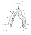
- the double slush skin 20 is produced and the simultaneous connection with a Plastic carrier 16 as an instrument carrier advantageously in one step in one Galvanoform 10.
- the double slush skin 20 according to FIG. 2 is also produced in FIG a galvanoform 10, only that for molding the double slush skin 20 to be produced Form stamp 30 is inserted into the electroform 10.
- demoulding the Double slush skin 20 from the electroform 10 is the in a subsequent step Glued to the inside of the double slush skin 20 with the plastic carrier 16.
- a double slush skin 20 is produced in conjunction with a Plastic carrier 16 according to the double slush technique known per se in a galvanoform 10.
- a first plastic layer 18 is thereby formed on the inner contour of the electroforming device 10 generated.
- a second expanding layer is then formed on the first plastic layer 18 Plastic layer 14 generated, with after inserting a plastic carrier 16, with a the inner contour of the double slush skin 20 determining form, in the electroform 10 of the Foaming process begins.
- the expanding material is connected the second plastic layer 14 with the plastic carrier 16.
- the double slush skin 20 with the plastic carrier 16 are removed from the galvanoform 10.
- demolding takes place Molded parts from a galvanoform 10 while largely avoiding Damage to the double slush skin 20 in the later visible area, in particular in the case of design-related, slight undercuts in the outer contour of the double slush skin 20 in that for demolding between the first plastic layer 18 and the Electroform 10 generates an overpressure, the overpressure over the electroform 10 is fed.
- the Supply of the overpressure via openings and / or arranged in the electroform 10 Micro holes 12.
- Pressure source 22 generated pressure to demold the double slush skin 20 and Plastic carrier 16 depends on the outer shape of the double slush skin 20 and on the adhesive forces that occur between the galvanoform 10 and the first plastic layer 18 of the double slush skin 20. In the case of design-related, slight undercuts caused by the External shape of the double slush skin 20 are specified, larger compressive forces to Demolding needed. Furthermore, the pressure force to be used is determined by the Material quality of the double slush skin 20 determined. It has to be secured, that the compressive forces do not become so great that they are on the later visible area Leave 20 traces on the surface of the double slush skin.
- the overpressure forces supplied for demolding are adjusted with regard to their Size and its entry location based on the total surface of the double slush skin 20.
- the pressure acting on the surface of the double slush skin 20 can be arranged of different cross-sectional areas of the individual openings and / or microholes Set 12. Furthermore, the pressure is adjusted by the arrangement of the individual openings and / or microholes 12 with regard to their distribution over the Entire surface of the galvanoform 10. According to the above conditions the individual openings and / or microholes 12 for feeding the Overpressure evenly or unevenly over the entire surface of the Galvanoform 10 arranged distributed.
- Another variant of the solution according to the invention provides the openings and / or Micro holes 12 in the electroform 10 for supplying the excess pressure in the area of the later Arrange invisible sections of the double slush skin 20.
- These areas are such Areas that are later punched out or milled and in which, for example Fittings, vents or the like can be arranged.
- the according to the device according to the invention by the arrangement and size individual breakthroughs and / or microholes 12 in the electroform 10 is reached Damage during demolding on the visible surface of the double slush skin 20 avoided.
- the formation of the double slush skin 20 as a composite component with the Plastic carrier 16 can also with light, design-related undercuts caused by the outer shape of the double slush skin 20 are predetermined, without problems and without Damage to the surface of the double slush skin 20 take place.
- FIG. 1 shows an already demolded double slush skin 20.
- the solution according to the invention can also be used in the production of the double slush skin 20 by means of a die 30, in which the connection of the double slush skin 20 with the plastic carrier 16 only after the double slush skin 20 has been removed from the mold is carried out.
- FIG. 10 A variant for demolding those connected to a plastic carrier 16 Double slush skin 20 from a galvanoform 10 is shown in FIG.
- ejector 28 for demolding those connected to the plastic carrier 16 Double slush skin 20 integrated.
- one or more ejectors 28 in the Galvanoform 10 may be arranged.
- the ejectors 28 include ejector plates 32 and actuating devices 34 arranged thereon.
- the ejector plates 32 are in corresponding recesses 36 are arranged so that one of the double slush skin 20 facing surface 38 into the surface 44 of the double slush skin 20 Galvanoform 10 merges.
- Double slush skin 20 and the ejector plates 32 are corresponding as negative form the surface shape of the double slush skin 20 to be demolded.
- the ejector plates 32 are advantageously arranged in the regions of FIG Surface of the double slush skin 20, which are no longer visible later. These areas are areas that are later punched or milled and in which, for example Fittings, vents or the like can be arranged.
- the ejectors 28 are in accordance with the double arrows 40 in demolding and Opposite direction slidably arranged in the electroform 10.
- the Ejector plates 32 by means of the actuating devices 34 in or out of the Recesses 36 relocatable.
- the actuators 34 are preferred arranged outside the actual galvanoform 10. Actuators of the Actuators 34 are guided through openings 42 of the electroform 10. Outside the galvanoform 10, the actuating devices 34 comprise not shown Mechanically, electrically, pneumatically, hydraulically or the like acting means for Moving the ejector 28.
- the illustration in FIG. 4 shows the recesses 36 relocated ejector plates 32.
- the double slush skin 20 with the plastic carrier 16 is so just demoulded.
- the Ejector 28 in its starting position. That is, the ejector plates 32 are located directly on the inner wall of the electroform 10.
- the mechanical, acting on the actuating devices 34 means acting electrically, pneumatically, hydraulically or the like in Demolding direction shifted. This is done by pressing out the Double slush skin 20 with the plastic carrier 16 through the ejector plates 32 Demolding from the galvanoform 10.
- the shape of the composite component can also lightweight, design-related undercuts, which are due to the outer shape of the Double slush skin 20 are specified, easily without damaging the surface of the Double slush skin 20 take place. After completing the molding process, the Ejector 28 moved back to its original position.
- the solution according to the invention can also be used in the production of Double slush skin 20 are used by means of a die 30, in which the connection the double slush skin 20 with the plastic carrier 16 only after the demolding Double skin 20 is performed.
- a double slush skin 20 is produced in an outer contour the double slush skin 20 determining electroform 10 and at least one die Inner contour of the double slush skin 20 defining counter shape, for example one Form stamp 30, with a cavity between electroform 10 and the form stamp 30 for expanding an expandable material to produce the double slush skin 20 is arranged.
- the double slush skin 20 consists of one in a first Method step on the inner wall of the electroform 10 produced skin 18 (first Plastic layer) and a second one produced in a further process step Plastic layer 14, which consists of an expandable material and which during the expansion process or the foaming process with the first Plastic layer 18 is connected.
- the temperature of the die 30 is influenced Foaming process in the process of forming the second plastic layer 14 to thereby Impairments in possible material fluctuations in the starting material as far as possible and to shorten the manufacturing time.
- the die 30 is compared to the ambient temperature heated tempering agent supplied.
- the temperature control agent is, for example, in In the form of hot water, oil, air or as another suitable medium by means of channels, Bores 24 or the like are guided into the interior of the die 30.
- the foaming process of the expanding one is on the one hand by the tempering agent Material of the second plastic layer 14 not only from the outside via the electroform 10 influenced, but also from the inside via the form stamp 30.
- the tempering agent Material of the second plastic layer 14 By appropriate Temperature supply can be influenced specifically on the educational process, whereby the manufacturing time can be reduced.
- the Supply of heated temperature control agents an expansion of the die 30. Through the appropriate temperature supply and the associated expansion of the die 30 is also specifically influenced on the formation of the wall thickness Double slush skin 20 taken.
- the die 30 After completion of the foaming process and the formation of the second plastic layer 14 is the die 30 through the holes 24 opposite to the Ambient temperature cooled cooling agent supplied. This will make the Cooling time of the second plastic layer 14 produced is reduced, thereby the Manufacturing time is further reduced overall.
- the Form stamp 30 by cooling the Form stamp 30 in turn influences the dimensional influence of the to be manufactured Double slush skin 20 taken.
- By appropriately tempering the die 30 is an influence on the size of the die 30 and thus the molded contour possible. Changes caused by material fluctuations in the source material the dimensional accuracy can be largely compensated.
- the arrangement of the channels or bores 24 within the die 30 can, as shown in Figure 2, transversely in the cutting direction of the die 30 or, as in Figure 3 shown taken longitudinally in the cutting direction of the die 30.
- the longitudinal holes in the lower Area of the die 30 connected to one another by transverse bores 26.
- the form stamp 30 can either only be used with heated or cooled temperature media.
- stamp 30 which is the negative form of Corresponds to the inner contour of the double slush skin 20 to be produced, from one manufacturing technology, mechanically easy-to-work material, while maintaining the Stability of the die 30 at the expense of necessary shape corrections To reduce fine adjustment or change in shape of the die 30 and to achieve a higher accuracy of the corrections to be made on the die 30.
- a surface 66 of the die can 30 mechanically easily processed with simple means. Accordingly necessary Changes in shape, fine adjustments or corrections can be made to the Form stamp 30 can be carried out with a high dimensional accuracy. That has at the same time the result is that the effort required for the necessary corrections is reduced becomes.
- the die 30 made of aluminum has proven to be particularly cheap or to manufacture from synthetic resin. These materials can be machined well and meet the conditions in the manufacturing process of the double slush skin 20.
- FIG. 10 shows a variant of the die 30 according to the invention.
- the die 30 consists of a stable core 62, whose surface area 64 in the area of the double slush skin 20 consists of a Production-technically, mechanically easy to process material. So that at Ensuring the stability of the die 30 accordingly necessary Changes in shape, fine adjustments or corrections to the stamp 30 can also be carried out with a high degree of dimensional accuracy and with simple means.
- the core 62 of the die 30 is advantageously made of steel, while the Surface 64 of the die 30 made of an aluminum or synthetic resin coating consists.
- Existing form stamp 30 can, as already described, to influence the educational and / or molding process of the double slush skin 20 with corresponding bores 24 and / or bores 26 are provided for supplying the temperature control agent.
- the outer shape of the double slush skin 20 is determined by its later use, for example as an instrument panel in the automotive industry, determined so that design-related Undercuts between the galvanoform 10 and the counterform, for example one Form stamp 30 or a plastic carrier 16, and thus a narrowing of the wall thickness of the double slush skin 20 to be formed cannot be avoided.
- a first cavity region 48 which through the inner wall of the Electroplating 10 and the outer wall of the counter mold (stamp 30) is formed and has a constant cross-sectional area, a second cavity region 50 with a smaller one than the first cross-sectional area of the first cavity region 48 Arranged cross-sectional area, which is immediately followed by a third cavity region 52 a cross-sectional area that increases compared to the second cross-sectional area is arranged.
- the third cavity area 52 Due to the direct arrangement of the third cavity area 52 on the In the second cavity area 50 with a smaller cross-sectional area, a material flow takes place of the expandable material 14 - during the expansion - corresponding to that in the 5 indicated material flow direction 46 from the cavity area 50 to the Cavity area 52.
- the cross-sectional expansion of the third cavity area 52 takes place up to a size at which the sum of the volumes of the second cavity region 50 and the third cavity region 52 approximately the sum of the volumes one assumed second cavity area 50 and third cavity area 52 constant cross-sectional area corresponding to the first cavity region 48 corresponds. This ensures that an approximately even distribution of the expandable material of the second plastic layer 14 over the entire Cavity area between the electroform 10 and die 30 takes place and that when expanding the material, no impermissible pressure increases on the electroform 10 arise.
- the Cross-sectional area corresponds to that of the first cavity region 48.
- a form stamp 30 or a plastic carrier 16 is used in the manufacture of the double slush skin 20 in the manufacture of the double slush skin 20.
- a die 30 takes place in a connection of the double slush skin 20 with a subsequent manufacturing process a plastic carrier 16 while using the plastic carrier 16 as Counterform during the expansion process of the material already the connection of the Double slush skin 20 is carried out with the plastic carrier 16.
- FIG Galvanoform 10 To improve the stability of the galvanoform 10 and to better comply with the Shape accuracy of the double slush skin 20 to be produced exists according to FIG Galvanoform 10 from several assemblies with different materials.
- the surface 56 of the double slush skin 20 to be produced consists of the assembly 56 of the Galvanoform 10 made of stainless steel.
- the invisible areas of the surface of the Double slush skin 20 are, as already stated, such areas that later can be punched out or milled out by arranging additional devices.
- the individual assemblies 58 made of nickel and those made of stainless steel Assemblies 56 are joined together to form electroform 10 by laser welding.
- the electroform 10 is the Stability of the galvanoform 10, when realizing a high dimensional accuracy, increased. This enables the assembly of stainless steel assemblies 56 Arrange modules with additional mechanical functions. In addition, the Assemblies of the galvanoform 10 if necessary by installing additional ones Parts extended or shortened by shortening the assemblies, or parts thereof.
- FIG. 7 shows a variant of the device according to the invention.
- ejectors 28 are as Assemblies with additional mechanical functions arranged.
- the ejectors 28 have the task, after completion of the double slush skin 20, this from the electroform 10 carry out.
- the galvanoform 10 consisting of several assemblies can also, like already described, with means for supplying an overpressure between the Electroplating 10 and the double slush skin 20 are provided.
- the invention Galvanoform 10 can both be used using a galvanoform 10 retracting die 30 to generate a defined inner contour of the Double slush skin 20, as well as using one introduced into the electroform 10 Plastic carrier 16.
- the Galvanoform 10 is designed so that it the in the manufacturing process Double slush skin 20 can absorb compressive forces occurring without changes in shape and thus has an increased bending stiffness compared to the known devices.
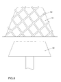
- 10 stiffeners in the form of ribs 60 are on the outside of the electroform arranged.
- the compressive forces occurring when retracting the counter mold (die 30) in the Galvanoform 10 as well as those arising during the molding process of the double slush skin 20 Compressive forces can be absorbed by the galvanoform 10 without these deformed in the process. This also changes the shape and contour of the one to be manufactured Double slush skin 20 excluded.
- the arrangement of the stiffeners or ribs 60 on the outside of the Galvanoform 10 takes place in the longitudinal and / or transverse direction.
- Figure 8 is one Diamond-shaped arrangement of the ribs 60 shown on the outside of the electroform 10.
- the corresponding stiffeners or the ribs 60 are, for example by laser welding or by galvanization on the outside of the electroform 10 upset.
- stiffeners can also be made of several assemblies existing galvanoforms 10 are arranged.
- the presented according to the invention Solutions can be used appropriately in combination without doing so again must also be addressed. With the solution according to the invention, the Formation, molding and demolding process in the production of a double slush skin 20 be actively influenced.
Landscapes
- Engineering & Computer Science (AREA)
- Mechanical Engineering (AREA)
- Manufacturing & Machinery (AREA)
- Physics & Mathematics (AREA)
- Fluid Mechanics (AREA)
- Moulding By Coating Moulds (AREA)
- Moulds For Moulding Plastics Or The Like (AREA)
Abstract
Description
- Figur 1
- eine Seitenansicht der erfindungsgemäßen Vorrichtung zur Herstellung einer Doppelslushhaut im Schnitt unter Verwendung eines Kunststoffträgers als Gegenform;
- Figur 2
- eine Seitenansicht der erfindungsgemäßen Vorrichtung zur Herstellung einer Doppelslushhaut im Schnitt unter Verwendung eines Formstempels als Gegenform;
- Figur 3
- eine Variante der erfindungsgemäßen Vorrichtung nach Figur 2;
- Figur 4
- eine Variante der erfindungsgemäßen Vorrichtung nach Figur 1;
- Figur 5
- eine weitere Variante der erfindungsgemäßen Vorrichtung gemäß Figur 2;
- Figur 6
- eine Schnittdarstellung der erfindungsgemäßen Galvanoform;
- Figur 7
- eine weitere Variante der erfindungsgemäßen Vorrichtung gemäß Figur 1 und
- Figuren 8 bis 10
- jeweils eine weitere Variante der erfindungsgemäßen Vorrichtung gemäß Figur 2.
- 10
- Galvanoform
- 12
- Durchbrüche und/oder Mikrolöcher
- 14
- zweite Kunststoffschicht
- 16
- Kunststoffträger
- 18
- erste Kunststoffschicht
- 20
- Doppelslushhaut
- 22
- Druckquelle
- 24
- Bohrungen
- 26
- Querbohrungen
- 28
- Auswerfer
- 30
- Formstempel
- 32
- Auswerferplatten
- 34
- Betätigungseinrichtung
- 36
- Ausnehmung
- 38
- Oberfläche
- 40
- Entformungs- und Gegenrichtung
- 42
- Öffnung
- 44
- Oberfläche
- 46
- Materialflussrichtung
- 48
- erster Hohlraumbereich
- 50
- zweiter Hohlraumbereich
- 52
- dritter Hohlraumbereich
- 54
- vierter Hohlraumbereich
- 56
- aus Edelstahl bestehende Baugruppe
- 58
- aus Nickel bestehende Baugruppe
- 60
- Rippen
- 62
- Kern des Formstempels
- 64
- Oberflächenbereich des Formstempels
- 66
- Oberfläche
Claims (70)
- Verfahren zur Herstellung einer Doppelslushhaut (20), wobei an einer Kontur einer Galvanoform (10) eine erste Kunststoffschicht (18) erzeugt wird, anschließend auf der ersten Kunststoffschicht (18) eine zweite expandierende Kunststoffschicht (14) erzeugt wird, deren Innenkontur durch einen Formstempel (30) oder durch einen Kunststoffträger (16) erzeugt wird, dadurch gekennzeichnet, dass bei der Herstellung einer Doppelslushhaut (20) der Bildungs-, und/oder Abform-, und/oder Entformungsprozess beeinflusst wird.
- Verfahrens nach Anspruch 1, dadurch gekennzeichnet, dass zum Entformen zwischen der ersten Kunststoffschicht (18) und der Form ein Überdruck erzeugt wird.
- Verfahren nach einem der vorhergehenden Ansprüche, dadurch gekennzeichnet, dass der Überdruck über die Galvanoform (10) zugeführt wird.
- Verfahren nach einem der vorhergehenden Ansprüche, dadurch gekennzeichnet, dass die Größe des Überdrucks einstellbar ist.
- Verfahren nach einem der vorhergehenden Ansprüche, dadurch gekennzeichnet, dass der Überdruck auf pneumatische Weise erzeugt wird.
- Verfahren nach einem der vorhergehenden Ansprüche, dadurch gekennzeichnet, dass der Überdruck über die Gesamtfläche der zu entformenden Doppelslushhaut (20) mit unterschiedlichen Größen zugeführt wird.
- Verfahren nach einem der vorhergehenden Ansprüche, dadurch gekennzeichnet, dass ein erhöhter Überdruck im Bereich der später nicht sichtbaren Abschnitte der zu entformenden Doppelslushhaut (20) zugeführt wird.
- Verfahren nach Anspruch 2 bis 6, dadurch gekennzeichnet, dass der Überdruck über die Gesamtfläche der zu entformenden Doppelslushhaut (20) gleich groß ist.
- Verfahrens nach Anspruch 1, dadurch gekennzeichnet, dass zur Beeinflussung des Bildungs- und/oder Abformprozesses der Kunststoffschichten der Formstempel (30) temperiert wird.
- Verfahrens nach Anspruch 9, dadurch gekennzeichnet, dass dem Formstempel (30) ein Temperierungsmittel zugeführt wird.
- Verfahrens nach Anspruch 9 und 10, dadurch gekennzeichnet, dass das Temperierungsmittel in das Innere des Formstempels (30) zugeführt wird.
- Verfahrens nach Anspruch 9 bis 11, dadurch gekennzeichnet, dass das Temperierungsmittel im Inneren des Formstempels (30) im Bereich der herzustellenden Kunststoffschichten zugeführt wird.
- Verfahrens nach Anspruch 9 bis 12, dadurch gekennzeichnet, dass das Temperierungsmittel Wasser, Öl, Luft oder ein ähnliches Medium ist.
- Verfahrens nach Anspruch 9 bis 13, dadurch gekennzeichnet, dass das Temperierungsmittel ein gegenüber der Umgebungstemperatur erwärmtes Medium ist.
- Verfahrens nach Anspruch 9 bis 13, dadurch gekennzeichnet, dass das Temperierungsmittel ein gegenüber der Umgebungstemperatur gekühltes Medium ist.
- Verfahrens nach Anspruch 9 bis 15, dadurch gekennzeichnet, dass beim Expansions- beziehungsweise Aufschäumprozess der Kunststoffschichten dem Formstempel (30) ein erwärmtes Medium als Temperierungsmittel zugeführt wird.
- Verfahrens nach Anspruch 16, dadurch gekennzeichnet, dass beim Ausformprozess der Kunststoffschichten dem Formstempel (30) ein gekühltes Medium als Temperierungsmittel zugeführt wird.
- Vorrichtung zur Herstellung einer Doppelslushhaut (20), mit einer die Außenkontur der Doppelslushhaut (20) bestimmenden Form und wenigstens einer die Innenkontur der Doppelslushhaut (20) definierenden Gegenform, wobei zwischen Form und Gegenform ein Hohlraum zum Expandieren eines expansionsfähigen Materials der Doppelslushhaut (20) ausgebildet ist, gekennzeichnet durch Mittel zur Beeinflussung des Bildungs-, und/oder Abform-, und/oder Entformungsprozess bei der Herstellung einer Doppelslushhaut (20).
- Vorrichtung nach Anspruch 18, dadurch gekennzeichnet, dass zum Entformen der Doppelslushhaut (20) eine Einrichtung zur Zuführung eines Überdruckes zwischen Galvanoform (10) und Doppelslushhaut (20) angeordnet ist.
- Vorrichtung nach Anspruch 19, dadurch gekennzeichnet, dass die Einrichtung zur Zuführung eines Überdruckes in der Galvanoform (10) angeordnete Durchbrüche (12) sind.
- Vorrichtung nach Anspruch 19, dadurch gekennzeichnet, dass die Einrichtung zur Zuführung eines Überdruckes in der Galvanoform (10) angeordnete Mikrolöcher (12) sind.
- Vorrichtung nach Anspruch 19 bis 21, dadurch gekennzeichnet, dass die Querschnittsflächen der einzelnen Durchbrüche und/oder Mikrolöcher (12) zur Zuführung des Überdruckes mit gleicher Größe ausgebildet sind.
- Vorrichtung nach Anspruch 19 bis 21, dadurch gekennzeichnet, dass die Querschnittsflächen der einzelnen Durchbrüche und/oder Mikrolöcher (12) zur Zuführung des Überdruckes mit unterschiedlichen Größen ausgebildet sind.
- Vorrichtung nach Anspruch 19 bis 23, dadurch gekennzeichnet, dass die Durchbrüche und/oder Mikrolöcher (12) zur Zuführung eines Überdruckes gleichmäßig verteilt über die gesamte Oberfläche der Galvanoform (10) angeordnet sind.
- Vorrichtung nach Anspruch 19 bis 23, dadurch gekennzeichnet, dass die Durchbrüche und/oder Mikrolöcher (12) zur Zuführung eines Überdruckes ungleichmäßig verteilt über die gesamte Oberfläche der Galvanoform (10) angeordnet sind.
- Vorrichtung nach Anspruch 19 bis 25, dadurch gekennzeichnet, dass die Durchbrüche und/oder Mikrolöcher (12) in der Galvanoform (10) zur Zuführung eines Überdruckes im Bereich der später nicht sichtbaren Abschnitte der Doppelslushhaut (20) angeordnet sind.
- Vorrichtung nach Anspruch 18, dadurch gekennzeichnet, dass der Formstempel (30) wenigstens eine Einrichtung zur Zuführung eines Temperierungsmittels umfasst.
- Vorrichtung nach Anspruch 27, dadurch gekennzeichnet, dass die Einrichtung zur Zuführung des Temperierungsmittels in den Formstempel (30) angeordnete Kanäle, Bohrungen (24) oder dergleichen sind.
- Vorrichtung nach Anspruch 27 und 28, dadurch gekennzeichnet, dass die Bohrungen (24) im Randbereich des Formstempels (30) angeordnet sind.
- Vorrichtung nach Anspruch 27 bis 29, dadurch gekennzeichnet, dass die Bohrungen (24) in Entformungsrichtung des Formstempels (30) verlaufend angeordnet sind.
- Vorrichtung nach Anspruch 27 bis 30, dadurch gekennzeichnet, dass die Bohrungen (24) quer zur Entformungsrichtung des Formstempels (30) verlaufend angeordnet sind.
- Vorrichtung nach Anspruch 27 bis 31, dadurch gekennzeichnet, dass in Entformungsrichtung des Formstempels (30) verlaufende Bohrungen (24) durch wenigstens eine, quer zur Entformungsrichtung angeordnete Bohrung (26) miteinander verbunden sind.
- Vorrichtung nach Anspruch 18, dadurch gekennzeichnet, dass in die Vorrichtung wenigstens ein Auswerfer (28) zum Entformen der Doppelslushhaut (20) integriert ist.
- Vorrichtung nach Anspruch 33, dadurch gekennzeichnet, dass der wenigstens eine Auswerfer (28) in die Galvanoform (10) integriert ist.
- Vorrichtung nach Anspruch 33 und 34, dadurch gekennzeichnet, dass die Auswerfer (28) aus einer Auswerferplatte (32) und einer Betätigungseinrichtung (34) bestehen.
- Vorrichtung nach Anspruch 33 bis 35, dadurch gekennzeichnet, dass die Form der Auswerferplatten (32) im Berührungsbereich mit der Oberfläche der Doppelslushhaut (20) als Negativform der Form der Doppelslushhaut (20) entspricht.
- Vorrichtung nach Anspruch 33 bis 36, dadurch gekennzeichnet, dass die Auswerferplatten (32) in einem Bereich der Oberfläche der zu entformenden Doppelslushhaut (20) angeordnet sind, der später nicht sichtbar ist.
- Vorrichtung nach Anspruch 33 bis 37, dadurch gekennzeichnet, dass die Auswerferplatten (32) in Entformungs- und Gegenrichtung (40) verschiebbar angeordnet sind.
- Vorrichtung nach Anspruch 33 bis 38, dadurch gekennzeichnet, dass an den Auswerferplatten (32) angeordnete Betätigungseinrichtungen (34) außerhalb der Galvanoform (10) angeordnet sind.
- Vorrichtung nach Anspruch 33 bis 39, dadurch gekennzeichnet, dass die Auswerfer (28) über die an den Betätigungseinrichtungen (34) angeordneten mechanisch, elektrisch, pneumatisch, hydraulisch oder dergleichen wirkenden Mitteln verschiebbar sind.
- Vorrichtung nach Anspruch 18, dadurch gekennzeichnet, dass einem ersten Hohlraumbereich (48) mit einer im Wesentlichen gleichbleibenden Querschnittsfläche, dem ein zweiter Hohlraumbereich (50) mit einer gegenüber der ersten Querschnittsfläche geringeren Querschnittsfläche zugeordnet ist, ein dritter Hohlraumbereich (52) mit einer gegenüber der zweiten Querschnittsfläche sich vergrößernden Querschnittsfläche zugeordnet ist.
- Vorrichtung nach Anspruch 41, dadurch gekennzeichnet, dass die Querschnittsfläche des dritten Hohlraumbereiches (52) erweitert ist.
- Vorrichtung nach Anspruch 41 und 42, dadurch gekennzeichnet, dass die Querschnittserweiterung des dritten Hohlraumbereiches (52) bis zu einer Größe erfolgt, bei dem die Summe der Volumina des zweiten Hohlraumbereiches (50) und dritten Hohlraumbereiches (52) annähernd der Summe der Volumina eines angenommenen zweiten Hohlraumbereiches (50) und dritten Hohlraumbereiches (52) bei gleichbleibender Querschnittsfläche entspricht.
- Vorrichtung nach Anspruch 41 bis 43, dadurch gekennzeichnet, dass dem dritten Hohlraumbereich (52) ein weiterer, vierter Hohlraumbereich (54) mit gleichbleibender Querschnittsfläche zugeordnet ist.
- Vorrichtung nach Anspruch 44, dadurch gekennzeichnet, dass die Querschnittsflächen des vierten Hohlraumbereiches (54) und des ersten Hohlraumbereiches (48) nahezu gleich groß sind.
- Vorrichtung nach Anspruch 41 bis 45, dadurch gekennzeichnet, dass die Gegenform ein Formstempel (30) ist.
- Vorrichtung nach Anspruch 41 bis 45, dadurch gekennzeichnet, dass die Gegenform ein beim Expandieren des Materials mit der Doppelslushhaut (20) verbindbarer Kunststoffträger (16) ist.
- Vorrichtung nach Anspruch 18, dadurch gekennzeichnet, dass die Galvanoform (10) aus wenigstens zwei Baugruppen besteht.
- Vorrichtung nach Anspruch 48, dadurch gekennzeichnet, dass die Baugruppen aus unterschiedlichen Materialien bestehen.
- Vorrichtung nach Anspruch 48 und 49, dadurch gekennzeichnet, dass die Baugruppen aus Nickel (58) und Edelstahl (56) bestehen.
- Vorrichtung nach Anspruch 48 bis 50, dadurch gekennzeichnet, dass die Baugruppen miteinander verschweißt sind.
- Vorrichtung nach Anspruch 48 bis 51, dadurch gekennzeichnet, dass die Baugruppen durch Laserschweißen miteinander verschweißt sind.
- Vorrichtung nach Anspruch 48 bis 52, dadurch gekennzeichnet, dass die aus Nickel bestehenden Baugruppen (58) im sichtbaren Bereich der Oberfläche der herzustellenden Doppelslushhaut (20) angeordnet sind.
- Vorrichtung nach Anspruch 48 bis 53, dadurch gekennzeichnet, dass die aus Edelstahl bestehenden Baugruppen (56) im später nicht sichtbaren Bereich der Oberfläche der herzustellenden Doppelslushhaut (20) angeordnet sind.
- Vorrichtung nach Anspruch 48 bis 54, dadurch gekennzeichnet, dass im Bereich der aus Edelstahl bestehenden Baugruppen (56) Baugruppen mit mechanischen Funktionen angeordnet sind.
- Vorrichtung nach Anspruch 48 bis 55, dadurch gekennzeichnet, dass die Baugruppen mit mechanischen Funktionen mechanisch betätigte Auswerfer (28) sind.
- Vorrichtung nach Anspruch 18, dadurch gekennzeichnet, dass an den Außenseiten der Galvanoform (10) Versteifungen angeordnet sind.
- Vorrichtung nach Anspruch 57, dadurch gekennzeichnet, dass die an der Außenseite der Galvanoform (10) angeordneten Versteifungen Rippen (60) sind.
- Vorrichtung nach Anspruch 57 und 58, dadurch gekennzeichnet, dass die Rippen (60) an der Außenseite der Galvanoform (10) in Längs- und/oder Querrichtung angeordnet sind.
- Vorrichtung nach Anspruch 57 und 58, dadurch gekennzeichnet, dass die Rippen (60) rautenförmig an der Außenseite der Galvanoform (10) angeordnet sind.
- Vorrichtung nach Anspruch 57 bis 60, dadurch gekennzeichnet, dass die Rippen (60) auf die Außenseite der Galvanoform (10) durch Laserschweißen aufgebracht sind.
- Vorrichtung nach Anspruch 57 bis 60, dadurch gekennzeichnet, dass die Rippen (60) auf die Außenseite der Galvanoform (10) aufgalvanisiert sind.
- Vorrichtung nach Anspruch 18, dadurch gekennzeichnet, dass der Formstempel (30) zumindest bereichsweise aus einem fertigungstechnisch, mechanisch leicht bearbeitbaren Material besteht.
- Vorrichtung nach Anspruch 63, dadurch gekennzeichnet, dass der Formstempel (30) aus Aluminium besteht.
- Vorrichtung nach Anspruch 63, dadurch gekennzeichnet, dass der Formstempel (30) aus Kunstharz besteht.
- Vorrichtung nach Anspruch 63, dadurch gekennzeichnet, dass ein Kern (62) des Formstempels (30) aus einem stabilen Material und ein Oberflächenbereich (64) des Formstempels (30) aus einem fertigungstechnisch, mechanisch leicht bearbeitbaren Material besteht.
- Vorrichtung nach Anspruch 66, dadurch gekennzeichnet, dass der Kern (62) des Formstempels (30) aus Stahl besteht.
- Vorrichtung nach Anspruch 66 und 67, dadurch gekennzeichnet, dass der Oberflächenbereich (64) des Formstempels (30) aus Aluminium besteht.
- Vorrichtung nach Anspruch 66 und 67, dadurch gekennzeichnet, dass der Oberflächenbereich (64) des Formstempels (30) aus Kunstharz besteht.
- Vorrichtung zur Herstellung einer Doppelslushhaut (20), mit einer die Außenkontur der Doppelslushhaut (20) bestimmenden Form und wenigstens einer die Innenkontur der Doppelslushhaut (20) definierenden Gegenform, wobei zwischen Form und Gegenform ein Hohlraum zum Expandieren eines expansionsfähigen Materials der Doppelslushhaut (20) ausgebildet ist, dadurch gekennzeichnet, dass die Mittel zur Beeinflussung des Bildungs-, und/oder Abform-, und/oder Entformungsprozess bei der Herstellung einer Doppelslushhaut (20) aus einer Kombination von mehreren Merkmalen der Ansprüche 19 bis 69 bestehen.
Applications Claiming Priority (14)
| Application Number | Priority Date | Filing Date | Title |
|---|---|---|---|
| DE10022645 | 2000-04-28 | ||
| DE10022686 | 2000-04-28 | ||
| DE10022644 | 2000-04-28 | ||
| DE2000122643 DE10022643A1 (de) | 2000-04-28 | 2000-04-28 | Vorrichtung zur Herstellung einer Doppelslushhaut |
| DE10022643 | 2000-04-28 | ||
| DE2000122646 DE10022646A1 (de) | 2000-04-28 | 2000-04-28 | Vorrichtung zur Herstellung einer Doppelslushhaut |
| DE10022642 | 2000-04-28 | ||
| DE2000122642 DE10022642A1 (de) | 2000-04-28 | 2000-04-28 | Vorrichtung zur Herstellung einer Doppelslushhaut |
| DE10022638 | 2000-04-28 | ||
| DE2000122644 DE10022644A1 (de) | 2000-04-28 | 2000-04-28 | Vorrichtung zur Herstellung einer Doppelslushhaut |
| DE10022646 | 2000-04-28 | ||
| DE2000122638 DE10022638A1 (de) | 2000-04-28 | 2000-04-28 | Verfahren und Vorrichtung zur Herstellung einer Doppelslushhaut |
| DE2000122686 DE10022686A1 (de) | 2000-04-28 | 2000-04-28 | Vorrichtung zur Herstellung einer Doppelslushhaut |
| DE2000122645 DE10022645A1 (de) | 2000-04-28 | 2000-04-28 | Verfahren und Vorrichtung zur Herstellung einer Doppelslushhaut |
Publications (2)
| Publication Number | Publication Date |
|---|---|
| EP1149677A2 true EP1149677A2 (de) | 2001-10-31 |
| EP1149677A3 EP1149677A3 (de) | 2001-12-12 |
Family
ID=27561720
Family Applications (1)
| Application Number | Title | Priority Date | Filing Date |
|---|---|---|---|
| EP01250116A Withdrawn EP1149677A3 (de) | 2000-04-28 | 2001-04-03 | Verfahren und Vorrichtung zur Herstellung einer Doppelsluhhaut |
Country Status (1)
| Country | Link |
|---|---|
| EP (1) | EP1149677A3 (de) |
Cited By (8)
| Publication number | Priority date | Publication date | Assignee | Title |
|---|---|---|---|---|
| DE10311667B4 (de) * | 2002-03-15 | 2005-03-10 | Peguform Gmbh & Co Kg | Verfahren zum Hinterschäumen von Slushschichten |
| DE102005012720A1 (de) * | 2005-03-19 | 2006-09-21 | Volkswagen Ag | Verfahren zur Herstellng eines mehrschichtigen Verkleidungselements |
| WO2007000132A1 (de) * | 2005-06-25 | 2007-01-04 | Intier Automotive Interiors Gmbh | Verfahren zur herstellung eines schaumformkörpers |
| DE102008003153A1 (de) * | 2008-01-03 | 2009-07-09 | Volkswagen Ag | Formkörper für den Innenraum eines Kraftfahrzeugs, Innenausbauteil eines Kraftfahrzeugs sowie Verfahren zur Herstellung eines Formkörpers |
| EP2260996A1 (de) | 2009-06-13 | 2010-12-15 | Galvanoform Gesellschaft für Galvanoplastik mbh | Formschale und Verfahren zur Herstellung einer Formschale |
| WO2012140474A1 (en) * | 2011-04-13 | 2012-10-18 | Partes S.R.L. | Process to mould objects with a dust material |
| CZ306437B6 (cs) * | 2009-11-18 | 2017-01-25 | Aura - Engineering Hranice S.R.O. | Zařízení pro výrobu PVC materiálu s povrchem imitujícím vzhled kůže metodou „slush-moulding” |
| CN109049469A (zh) * | 2018-09-06 | 2018-12-21 | 陈烈 | 一种耐高压的管材加工装置及其加工方法 |
Family Cites Families (3)
| Publication number | Priority date | Publication date | Assignee | Title |
|---|---|---|---|---|
| IT1273580B (it) * | 1995-04-19 | 1997-07-08 | Ilpea Ind Spa | Procedimento per la formatura per colaggio a rifiuto di manufatti quali finte pelli o simili di materiali termoplastici termoindurenti ed elastomeri aventi almeno uno strato espanso con spessori controllati e predeterminati |
| IT1284038B1 (it) * | 1996-06-20 | 1998-05-08 | Ilpea Ind Spa | Procedimento perfezionato per la formatura di manufatti quali finte pelli o simili da materiali termoplastici, termoindurenti o |
| JPH11268059A (ja) * | 1998-03-23 | 1999-10-05 | Mitsuboshi Belting Ltd | パウダースラッシュ成形方法及びパウダースラッシュ成形システム |
-
2001
- 2001-04-03 EP EP01250116A patent/EP1149677A3/de not_active Withdrawn
Cited By (10)
| Publication number | Priority date | Publication date | Assignee | Title |
|---|---|---|---|---|
| DE10311667B4 (de) * | 2002-03-15 | 2005-03-10 | Peguform Gmbh & Co Kg | Verfahren zum Hinterschäumen von Slushschichten |
| DE10311667B8 (de) * | 2002-03-15 | 2005-07-14 | Peguform Gmbh & Co. Kg | Verfahren zum Hinterschäumen von Slushschichten |
| DE102005012720A1 (de) * | 2005-03-19 | 2006-09-21 | Volkswagen Ag | Verfahren zur Herstellng eines mehrschichtigen Verkleidungselements |
| WO2007000132A1 (de) * | 2005-06-25 | 2007-01-04 | Intier Automotive Interiors Gmbh | Verfahren zur herstellung eines schaumformkörpers |
| DE102008003153A1 (de) * | 2008-01-03 | 2009-07-09 | Volkswagen Ag | Formkörper für den Innenraum eines Kraftfahrzeugs, Innenausbauteil eines Kraftfahrzeugs sowie Verfahren zur Herstellung eines Formkörpers |
| EP2260996A1 (de) | 2009-06-13 | 2010-12-15 | Galvanoform Gesellschaft für Galvanoplastik mbh | Formschale und Verfahren zur Herstellung einer Formschale |
| CZ306437B6 (cs) * | 2009-11-18 | 2017-01-25 | Aura - Engineering Hranice S.R.O. | Zařízení pro výrobu PVC materiálu s povrchem imitujícím vzhled kůže metodou „slush-moulding” |
| WO2012140474A1 (en) * | 2011-04-13 | 2012-10-18 | Partes S.R.L. | Process to mould objects with a dust material |
| CN109049469A (zh) * | 2018-09-06 | 2018-12-21 | 陈烈 | 一种耐高压的管材加工装置及其加工方法 |
| CN109049469B (zh) * | 2018-09-06 | 2023-05-12 | 陈烈 | 一种耐高压的管材加工装置及其加工方法 |
Also Published As
| Publication number | Publication date |
|---|---|
| EP1149677A3 (de) | 2001-12-12 |
Similar Documents
| Publication | Publication Date | Title |
|---|---|---|
| DE102012110419B4 (de) | Vorrichtung und Verfahren zum Herstellen eines Crash-Pads | |
| EP3186057B1 (de) | Verfahren und vorrichtung zur herstellung von formteilen | |
| DE102012024056A1 (de) | Verfahren zur Herstellung eines Kunststoffbauteils und Spritzgießwerkzeug zur Durchführung des Verfahrens | |
| DE102004040942A1 (de) | Verfahren und Vorrichtung zur Herstellung von Zierteilen | |
| EP1747977A1 (de) | Verfahren zum Herstellen eines geschäumten Bauteils und Schäumwerkzeug zur Anwendung dieses Verfahrens | |
| DE102004035759B4 (de) | Verfahren zur Herstellung eines Dekorformteiles | |
| DE102018100576A1 (de) | Verfahren zur Herstellung eines Formteils mit einer Sichtfläche mit verschiedenen Oberflächenbereichen | |
| DE102011117267A1 (de) | Verfahren und Vorrichtung zur Herstellung von beschichteten Formteilen | |
| DE102008037131B4 (de) | Vorrichtung zum Herstellen eines formstabilen, sichtbaren Verkleidungsteils für ein Kraftfahrzeug sowie form- und narbgebende Schale zum lösbaren Verbinden mit einer Werkzeughälfte einer Spritzgießmaschine | |
| EP2326479B1 (de) | Verfahren und vorrichtung zur herstellung eines formteils mit mehreren aneinander grenzenden, unterschiedlichen dekorbereichen | |
| DE69615013T2 (de) | Verfahren zum formen von mehrschichtigen gegenständen, deren schichtdichte kontrolliert ist | |
| DE102004034930A1 (de) | Verfahren zum Formen einer Fahrzeug-Verkleidungskomponente | |
| EP0817715A1 (de) | Verfahren und vorrichtung zum strangpressen von kunststoffschmelzen zu hohlkammerprofilen | |
| DE10202246B4 (de) | Vorrichtung und Verfahren zum Herstellen optischer Formteile aus Kunstoff | |
| EP2877332B1 (de) | Verfahren zur herstellung eines kunststoffbauteils | |
| EP3328607B1 (de) | Verfahren und vorrichtung zum herstellen eines kaschierten formteils | |
| DE102014112890A1 (de) | Vorrichtung und Verfahren zur Herstellung einer Verzierung für ein Fahrzeug | |
| DE4142392A1 (de) | Verfahren und vorrichtung zum herstellen von kunststoff-formstuecken mit bereichsweise reduzierter wandstaerke | |
| WO1998036893A1 (de) | Verfahren und vorrichtung zur herstellung von kunststoff-formteilen durch blasformen | |
| DE10110908A1 (de) | Verfahren zur Herstellung eines mehrschichtigen Verbundteils und Werkzeug | |
| DE102013224656B4 (de) | Schäumwerkzeug | |
| DE10022645A1 (de) | Verfahren und Vorrichtung zur Herstellung einer Doppelslushhaut | |
| EP2769828B1 (de) | Verfahren und Werkzeug-Station zur Herstellung eines Verkleidungsteils | |
| DE102011102182B4 (de) | Vorrichtung und Verfahren zum Herstellen von mehrfarbigen Kunststoffbauteilen | |
| DE102016005954B4 (de) | Verfahren und Vorrichtung zur Herstellung eines thermoplastischen Schaumgussbauteils mit wenigstens einer Sollbruchstelle |
Legal Events
| Date | Code | Title | Description |
|---|---|---|---|
| PUAI | Public reference made under article 153(3) epc to a published international application that has entered the european phase |
Free format text: ORIGINAL CODE: 0009012 |
|
| PUAL | Search report despatched |
Free format text: ORIGINAL CODE: 0009013 |
|
| AK | Designated contracting states |
Kind code of ref document: A2 Designated state(s): AT BE CH CY DE DK ES FI FR GB GR IE IT LI LU MC NL PT SE TR Kind code of ref document: A2 Designated state(s): DE ES FR GB IT |
|
| AX | Request for extension of the european patent |
Free format text: AL;LT;LV;MK;RO;SI |
|
| AK | Designated contracting states |
Kind code of ref document: A3 Designated state(s): AT BE CH CY DE DK ES FI FR GB GR IE IT LI LU MC NL PT SE TR |
|
| AX | Request for extension of the european patent |
Free format text: AL;LT;LV;MK;RO;SI |
|
| 17P | Request for examination filed |
Effective date: 20020612 |
|
| AKX | Designation fees paid |
Free format text: DE ES FR GB IT |
|
| 17Q | First examination report despatched |
Effective date: 20040202 |
|
| GRAP | Despatch of communication of intention to grant a patent |
Free format text: ORIGINAL CODE: EPIDOSNIGR1 |
|
| STAA | Information on the status of an ep patent application or granted ep patent |
Free format text: STATUS: THE APPLICATION IS DEEMED TO BE WITHDRAWN |
|
| 18D | Application deemed to be withdrawn |
Effective date: 20060215 |