EP1149023B1 - Bung barrel - Google Patents
Bung barrel Download PDFInfo
- Publication number
- EP1149023B1 EP1149023B1 EP00903525A EP00903525A EP1149023B1 EP 1149023 B1 EP1149023 B1 EP 1149023B1 EP 00903525 A EP00903525 A EP 00903525A EP 00903525 A EP00903525 A EP 00903525A EP 1149023 B1 EP1149023 B1 EP 1149023B1
- Authority
- EP
- European Patent Office
- Prior art keywords
- barrel
- housing
- edge
- lateral walls
- transitions
- Prior art date
- Legal status (The legal status is an assumption and is not a legal conclusion. Google has not performed a legal analysis and makes no representation as to the accuracy of the status listed.)
- Expired - Lifetime
Links
- 229920001169 thermoplastic Polymers 0.000 claims description 3
- 230000002093 peripheral effect Effects 0.000 claims 1
- 230000007704 transition Effects 0.000 abstract description 29
- 239000012815 thermoplastic material Substances 0.000 abstract 1
- 238000004519 manufacturing process Methods 0.000 description 4
- 239000000463 material Substances 0.000 description 3
- 239000004033 plastic Substances 0.000 description 3
- 229920003023 plastic Polymers 0.000 description 3
- 238000007664 blowing Methods 0.000 description 2
- 230000007423 decrease Effects 0.000 description 2
- 230000000694 effects Effects 0.000 description 2
- 238000000034 method Methods 0.000 description 2
- 239000011324 bead Substances 0.000 description 1
- 238000000071 blow moulding Methods 0.000 description 1
- 230000009969 flowable effect Effects 0.000 description 1
- 239000007788 liquid Substances 0.000 description 1
- 238000000465 moulding Methods 0.000 description 1
- 238000007493 shaping process Methods 0.000 description 1
- 230000035939 shock Effects 0.000 description 1
- 239000002689 soil Substances 0.000 description 1
- 239000004416 thermosoftening plastic Substances 0.000 description 1
Images


Classifications
-
- B—PERFORMING OPERATIONS; TRANSPORTING
- B65—CONVEYING; PACKING; STORING; HANDLING THIN OR FILAMENTARY MATERIAL
- B65D—CONTAINERS FOR STORAGE OR TRANSPORT OF ARTICLES OR MATERIALS, e.g. BAGS, BARRELS, BOTTLES, BOXES, CANS, CARTONS, CRATES, DRUMS, JARS, TANKS, HOPPERS, FORWARDING CONTAINERS; ACCESSORIES, CLOSURES, OR FITTINGS THEREFOR; PACKAGING ELEMENTS; PACKAGES
- B65D1/00—Containers having bodies formed in one piece, e.g. by casting metallic material, by moulding plastics, by blowing vitreous material, by throwing ceramic material, by moulding pulped fibrous material, by deep-drawing operations performed on sheet material
- B65D1/12—Cans, casks, barrels, or drums
- B65D1/20—Cans, casks, barrels, or drums characterised by location or arrangement of filling or discharge apertures
Definitions
- the invention relates to a bung from thermoplastic Plastic according to the preamble of claim 1.
- the invention has for its object a bung from to manufacture thermoplastic so that the residual emptying has even better properties than that Barrel according to EP 0 291 695 A2 and thereby easy to manufacture is.
- the invention can be summarized in that the two transitions each side wall of the case delimit above and below from the front boundary wall the same in the direction of the edge region of the barrel diverge with the result that the slope of each side wall decreases from the front wall towards the edge area.
- a bung is known from EP 0 515 390 B1, in which the top floor in addition to or next to the bunghole housing an essentially circular segment-shaped surface part or has a bevel, the bevel its lowest point on the side of the barrel jacket in the close range of the bunghole.
- this configuration has Consequence that a relatively large number in the area of the top floor curved and angled wall areas are available to the Part run approximately at right angles to each other and a stiffening of the topsoil, which when the Upper floor through shock and impact to uncontrollable tensions and impermissible stresses on the plastic material can lead.
- the application of the invention leads to a simpler design because the top floor next to the bunghole housing no further bevels and circular sections Areas needed to achieve the desired effect.
- Another advantage of the barrel according to the invention is in that since the side walls of the housing are flatter than in the prior art, the shape of the barrel in Blowing process is easier. This is particularly why Meaning because normally the interface of the in general two-part blow mold through the nozzle and thus through the nozzle housing runs with the result that the preform, from which the barrel by applying internal pressure is made between the two moldings straight is clamped near the area along the parting surface, in which the preform to form strongly angled and curved wall areas such. B. in the area of the housing must be deformed.
- transitions between the side walls of the housing and its Soil can run essentially parallel to each other. But it can also be useful to make these transitions from the front boundary wall of the housing in the direction to let something converge on the rim of the barrel, with the result that the bottom of the case towards the barrel edge somewhat becomes narrower and thus the two transitions even closer lie on the bung hole, which means that the residual emptying additionally is improved.
- Stackable bung barrel 10 has a barrel body 12, a Upper floor 14 and a lower floor 16.
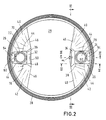
- the top shelf 14 is provided with two trough-shaped depressions, each one Form housing 18 or 20 for a nozzle 22 or 24.
- everyone Neck limits an opening 25 and 26.
- the barrel 10 is in the Area of the top floor 14 with a circumferential transport ring 28 provided, which is supported by a circumferential web 58. The latter delimits an open top with the top floor 14 Slot 30.
- the barrel usually only one of the two openings of the barrel serves the remaining drain while the other opening for normal Emptying the barrel using, for example a pump enclosed pipe is used, which is inserted through the opening into the interior of the barrel. That the This housing can also be assigned to this opening be carried out in the usual way, that is to say as close as possible to get large stacking area.
- the barrel according to the Drawing is provided with two openings for residual emptying and shows possible different configurations of the Housing.
- both housings 18, 20 The depth of both housings 18, 20 is such that the respective Spigot 22 or 24 not up over the top Boundary surface 29 of the top floor, which is also a stacking surface serves, protrudes.
- Each of the two arranged in the edge region of the top floor 14 Housing 18, 20 is at its barrel edge or ring 28 facing side open.
- the ring 28 each facing side of the nozzle 22 or 24 is that Housing bounded by an end wall 32 and 34, respectively, which is inclined between the bottom 36 or 38 of the housing and the top floor 14 runs.
- transitions 44 between the housing base 36 and 38 and of the respective wall 40 or 42 and between the respective Wall and the top floor 14 provided, the latter Transitions are designated by 46.
- transitions delimiting the end walls 32 and 34 respectively 48, 50 which are substantially parallel the transitions 44 and 46 are arranged in a divergent manner such that starting from the respectively associated end wall 32 or 34 of the Distance between the transitions 44, 46 towards the L-ring and thus the barrel edge increases.
- each Housing 18, 20 and the housing base 36 and 38 extend close to the nozzle 22 or 24, so that when the upper transitions 46 an angle ⁇ of, for example, 140 ° include, each side wall 40, 42 an extension of about 70 ° in radians between the lower transition 44 and the upper transition 46 has.
- the respective radians therefore correspond to Length of the transition 70 between the side wall 40 and 42 on the one hand and the limitation of the groove 30 on the other. Since the Length of the transition 70 also in relation to the emptying in a certain position of the barrel determines the slope, the latter can therefore also about the choice of the size of the Angle ⁇ can be determined.
- An angle ⁇ of more than 180 ° is not normally considered if the keg is stackable should be, since then the stacking area will be reduced too much and there would be a risk that the nozzle would be a load-bearing one Function would have to take over.
- the housing 20 shown on the right in FIG. 2 runs the two transitions 44 from the end wall 34 starting essentially parallel to the barrel edge, on which the housing limited only on three sides by the walls is open. The latter also applies to the one shown on the left in FIG. 2 Housing 18, the lower transitions 44 of the side walls however, starting from the associated end wall 32, converge somewhat towards the edge of the barrel, causing the flowable filling material through the oblique side walls 42, 44 is brought closer to the outlet opening 26.
- Fig. 3 reveals that the bottom 36 of the housing 18 in the area between nozzle 22 and the barrel edge with a fold 52 is provided which one up from the housing bottom 36 protruding bead 54 forms a recess 56 on the inside of the housing base 36 corresponds.
- This fold forms a deformation zone between the barrel edge or the annular web 58 carrying the transport ring 28 on the one hand and the respective nozzle 22 and 24 on the other hand, the serves to act on the barrel edge towards the nozzle Intercept forces at least to the extent that no inadmissible Strains occur in the area of the nozzle. This effect is caused by a temporary deformation of the Crease reached. However, this is irrelevant since the fold after the impact or impact stress is back in the original situation springs back.
- the barrel 10 is on the inside with a essentially radial groove-shaped depression 60 (Fig. 3 and 5) provided, which is different from the fold 52 caused depression 56 approximately radially through the in the normal position of the barrel lower area of the nozzle 22 or 24 in the opening 25 and 26 bounded by this extends.
- a essentially radial groove-shaped depression 60 (Fig. 3 and 5) provided, which is different from the fold 52 caused depression 56 approximately radially through the in the normal position of the barrel lower area of the nozzle 22 or 24 in the opening 25 and 26 bounded by this extends.
- Edge area provided with a recess 62.
- the gutter 60 should enable the barrel to be emptied even further, thus also in the area between the nozzle and the barrel edge Product residues, if necessary by swiveling accordingly of the barrel from which the barrel can flow.
- Fig. 3 of the drawing it is shown that during the emptying of the rest of the filling, the latter approximately from area A over the lateral, preferably flat, boundary walls 40, 42 in the direction of arrows 64 in area B between the nozzles and barrel edge flows and from there in particular through the channel-shaped Well 60 in the nozzle and through this from the Barrel runs out.
Landscapes
- Engineering & Computer Science (AREA)
- Ceramic Engineering (AREA)
- Mechanical Engineering (AREA)
- Containers Having Bodies Formed In One Piece (AREA)
- Containers And Packaging Bodies Having A Special Means To Remove Contents (AREA)
- Ultra Sonic Daignosis Equipment (AREA)
- Rigid Containers With Two Or More Constituent Elements (AREA)
- Cartons (AREA)
- Valve-Gear Or Valve Arrangements (AREA)
- Surgical Instruments (AREA)
- Prostheses (AREA)
- Connector Housings Or Holding Contact Members (AREA)
- Basic Packing Technique (AREA)
- Details Of Rigid Or Semi-Rigid Containers (AREA)
- General Details Of Gearings (AREA)
- Glass Compositions (AREA)
- Cyclones (AREA)
- Closures For Containers (AREA)
- Injection Moulding Of Plastics Or The Like (AREA)
- Stackable Containers (AREA)
Abstract
Description
Die Erfindung betrifft ein Spundfaß aus thermoplastischem Kunststoff gemäß dem Oberbegriff des Anspruchs 1.The invention relates to a bung from thermoplastic Plastic according to the preamble of claim 1.
Bei einem aus EP 0 291 695 A2 bekannten derartigen Spundfaß ist die Anordnung so getroffen, daß der Spundlochstutzen zumindest teilweise in das Innere des Fasses hineinragt und an seinem Abschnitt, der sich im Inneren des Fasses befindet, mit wenigstens einer Durchbrechung versehen ist, um eine weitgehende Entleerung des Fasses zu ermöglichen. Diese Ausgestaltung hat den Nachteil, daß der Spundlochstutzen gesondert hergestellt und in einem besonderen Arbeitsgang am Fasskörper angebracht werden muß. Es können somit die Vorteile des Blasverfahrens, das vielfach für die Fertigung derartiger Kunststoff-Fässer benutzt wird und eine einstückige Herstellung in einem Arbeitsgang ermöglicht, nicht genutzt werden.In a bung barrel of this type known from EP 0 291 695 A2 the arrangement is made so that the bunghole at least partially protrudes into the interior of the barrel and on its section, which is inside the barrel, with at least one opening is provided to a large extent To allow emptying of the barrel. This configuration has the disadvantage that the bunghole connector is separate manufactured and in a special operation on the barrel body must be attached. The advantages of the blowing process, often for the production of such plastic drums is used and a one-piece production in allows one operation to be used.
Der Erfindung liegt die Aufgabe zugrunde, ein Spundfaß aus thermoplastischem Kunststoff so herzustellen, das bezüglich der Restentleerung noch bessere Eigenschaften aufweist als das Faß gemäß EP 0 291 695 A2 und dabei auf einfache Weise herstellbar ist.The invention has for its object a bung from to manufacture thermoplastic so that the residual emptying has even better properties than that Barrel according to EP 0 291 695 A2 and thereby easy to manufacture is.
Diese Aufgabe wird gelöst durch die Anwendung der im Kennzeichen des Anspruches 1 angegebenen Merkmale.This problem is solved by using the in the license plate of claim 1 specified features.
Die Erfindung läßt sich dahingehend zusammenfassen, daß die beiden Übergänge, die jede Seitenwand des Gehäuses jeweils oben und unten begrenzen, von der stirnseitigen Begrenzungswand desselben in Richtung auf den Randbereich des Fasses divergieren mit der Folge, daß die Neigung jeder Seitenwand von der Stirnwand in Richtung auf den Randbereich abnimmt.The invention can be summarized in that the two transitions each side wall of the case delimit above and below from the front boundary wall the same in the direction of the edge region of the barrel diverge with the result that the slope of each side wall decreases from the front wall towards the edge area.
Zwar ist aus EP 0 515 390 B1 ein Spundfaß bekannt, bei welchem der Oberboden zusätzlich zum bzw. neben dem Spundlochstutzen-Gehäuse ein im wesentlichen kreisabschnittsförmiges Flächenteil bzw. eine Abschrägung aufweist, wobei die Abschrägung ihre tiefste Stelle auf der Seite des Faßmantels im Nahbereich des Spundlochstutzens hat. Diese Ausgestaltung hat jedoch zur Folge, daß im Bereich des Oberbodens verhältnismäßig viele gebogene und abgewinkelte Wandbereiche vorhanden sind, die zum Teil etwa rechtwinklig zueinander verlaufen und eine Versteifung des Oberbodens bewirken, die bei Beanspruchungen des Oberbodens durch Stoß und Schlag zu unkontrollierbaren Spannungen und unzulässigen Beanspruchungen des Kunststoffmaterials führen kann. Die Anwendung der Erfindung führt zu einer einfacheren Ausgestaltung, da der Oberboden neben dem Spundlochgehäuse keine weiteren Abschrägungen und kreisabschnittförmige Flächen benötigt, um den angestrebten Effekt zu erzielen.A bung is known from EP 0 515 390 B1, in which the top floor in addition to or next to the bunghole housing an essentially circular segment-shaped surface part or has a bevel, the bevel its lowest point on the side of the barrel jacket in the close range of the bunghole. However, this configuration has Consequence that a relatively large number in the area of the top floor curved and angled wall areas are available to the Part run approximately at right angles to each other and a stiffening of the topsoil, which when the Upper floor through shock and impact to uncontrollable tensions and impermissible stresses on the plastic material can lead. The application of the invention leads to a simpler design because the top floor next to the bunghole housing no further bevels and circular sections Areas needed to achieve the desired effect.
Tatsächlich sind es die seitlichen Begrenzungswände des Spundlochstutzen-Gehäuses, die aufgrund ihres erfindungsgemäßen Verlaufes in der Entleerungsposition des Fasses zugleich auch eine weitestgehende Restentleerung ermöglichen. Allgemein wird gelten, daß mit zunehmendem Winkel, welcher von den beiden seitlichen Wandungen des Spundlochstutzen-Gehäuses gebildet wird, eine zunehmende Restentleerung erreicht wird. Da andererseits mit zunehmendem Winkel die verbleibende Fläche des Oberbodens, die als Stapelfläche benutzt wird, abnimmt, wird es in der Praxis darauf ankommen, ein Optimum bezüglich beider Erfordernisse zu finden. Dies ist ohne weiteres möglich, da beispielsweise bei einem Winkel von 140°, der von den beiden Seitenwänden an ihrem Übergang zum Oberboden eingeschlossen wird, im allgemeinen einen allen praktischen Erfordernissen genügende Restentleerung erreichbar und die Stapelfläche ausreichend groß ist.In fact, it is the side boundary walls of the Bunghole connector housing, due to their invention Course in the emptying position of the barrel at the same time also enable the greatest possible residual emptying. Generally will apply that with increasing angle, which of the two lateral walls of the bunghole housing formed increasing residual emptying is achieved. There on the other hand, with increasing angle, the remaining area of the top floor, which is used as a stacking surface, in practice it will be important to find the optimum to find both requirements. This is easily possible because, for example, at an angle of 140 ° from the included both side walls at their transition to the top floor will generally meet all practical requirements sufficient residual emptying and the stacking area is sufficiently large.
Ein weiterer Vorteil des Fasses gemäß der Erfindung besteht darin, daß, da die Seitenwände des Gehäuses flacher verlaufen als beim Stand der Technik, die Formgebung des Fasses im Blasverfahren einfacher ist. Dies ist insbesondere deshalb von Bedeutung, weil normalerweise die Trennfläche der im allgemeinen zweiteiligen Blasform durch den Stutzen und damit durch das Stutzengehäuse verläuft mit der Folge, daß der Vorformling, aus welchem das Faß durch Anwendung von innerem Überdruck hergestellt wird, zwischen den beiden Formteilen gerade nahe dem Bereich entlang der Trennfläche eingespannt ist, in welchem der Vorformling zur Bildung von stark abgewinkelten und gebogenen Wandbereichen z. B. im Bereich des Gehäuses verformt werden muß. Das Faß gemäß der Erfindung verringert auf Grund der Ausgestaltung des Gehäuses die sich daraus ergebenden Probleme. Auch ist das Entformen des Fasses gemäß der Erfindung auf Grund seiner Ausgestaltung des Gehäusebereiches merklich einfacher.Another advantage of the barrel according to the invention is in that since the side walls of the housing are flatter than in the prior art, the shape of the barrel in Blowing process is easier. This is particularly why Meaning because normally the interface of the in general two-part blow mold through the nozzle and thus through the nozzle housing runs with the result that the preform, from which the barrel by applying internal pressure is made between the two moldings straight is clamped near the area along the parting surface, in which the preform to form strongly angled and curved wall areas such. B. in the area of the housing must be deformed. The barrel reduced according to the invention due to the design of the housing, the resulting Problems. Also the demolding of the barrel is according to the Invention due to its design of the housing area noticeably easier.
Die Übergänge zwischen den Seitenwänden des Gehäuses und dessen Bodens können im wesentlichen parallel zueinander verlaufen. Es kann aber auch zweckmäßig sein, diese Übergänge von der stirnseitigen Begrenzungswand des Gehäuses in Richtung auf den Faßrand etwas konvergieren zu lassen, mit dem Ergebnis, daß der Gehäuseboden in Richtung auf den Faßrand etwas schmaler wird und damit auch die beiden Übergänge noch näher am Spundloch liegen, wodurch die Restentleerung zusätzlich verbessert wird.The transitions between the side walls of the housing and its Soil can run essentially parallel to each other. But it can also be useful to make these transitions from the front boundary wall of the housing in the direction to let something converge on the rim of the barrel, with the result that the bottom of the case towards the barrel edge somewhat becomes narrower and thus the two transitions even closer lie on the bung hole, which means that the residual emptying additionally is improved.
In der Zeichnung ist ein Ausführungsbeispiel der Erfindung dargestellt. Es zeigen:
- Fig. 1
- die Seitenansicht eines Spundfasses mit zwei Spundlochstutzen, deren Gehäuse beide für die Restentleerung eingerichtet sind,
- Fig. 2
- die dazugehörige Draufsicht, wobei die beiden Gehäuse unterschiedlich ausgeführt sind,
- Fig. 3
- einen Schnitt nach der Linie III-III der Fig. 2,
- Fig. 4
- einen Schnitt nach der Linie IV-IV der Fig. 2,
- Fig. 5
- einen Schnitt gemäß der Linie V-V der Fig. 3.
- Fig. 6
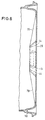
- einen Schnitt nach der Linie VI-VI der Fig. 2.
- Fig. 1
- the side view of a bung with two bung holes, the housing of which are both set up for residual emptying,
- Fig. 2
- the associated top view, the two housings being designed differently,
- Fig. 3
- 2 shows a section along the line III-III of FIG. 2,
- Fig. 4
- 2 shows a section along the line IV-IV of FIG. 2,
- Fig. 5
- a section along the line VV of FIG. 3rd
- Fig. 6
- a section along the line VI-VI of Fig. 2nd
Das in der Zeichnung dargestellte Ausführungsbeispiel eines
stapelbaren Spundfasses 10 weist einen Faßkörper 12, einen
Oberboden 14 und einen Unterboden 16 auf. Der Oberboden 14 ist
mit zwei muldenförmigen Vertiefungen versehen, die jeweils ein
Gehäuse 18 bzw. 20 für einen Stutzen 22 bzw. 24 bilden. Jeder
Stutzen begrenzt eine Öffnung 25 bzw. 26. Das Faß 10 ist im
Bereich des Oberbodens 14 mit einem umlaufenden Transportring
28 versehen, der von einem umlaufenden Steg 58 getragen ist.
Letzterer begrenzt mit dem Oberboden 14 eine noch oben offene
Nut 30.The embodiment shown in the drawing
Üblicherweise dient nur eine der beiden Öffnungen des Fasses der Restentleerung, während die andere Öffnung für die normale Entleerung des Fasses beispielsweise unter Verwendung eines eine Pumpe eingeschlossenen Rohres benutzt wird, welches durch die Öffnung in das Faßinnere eingeführt wird. Das dem Stutzen dieser Öffnung zugeordnete Gehäuse kann deshalb auch in üblicher Weise, also enger ausgeführt sein, um eine möglichst große Stapelfläche zu erhalten. Das Faß gemäß der Zeichnung ist mit zwei Öffnungen für die Restentleerung versehen und zeigt mögliche unterschiedliche Ausgestaltungen des Gehäuses.Usually only one of the two openings of the barrel serves the remaining drain while the other opening for normal Emptying the barrel using, for example a pump enclosed pipe is used, which is inserted through the opening into the interior of the barrel. That the This housing can also be assigned to this opening be carried out in the usual way, that is to say as close as possible to get large stacking area. The barrel according to the Drawing is provided with two openings for residual emptying and shows possible different configurations of the Housing.
Die Tiefe beider Gehäuse 18, 20 ist so bemessen, daß der jeweilige
Stutzen 22 bzw. 24 nicht nach oben über die obere
Begrenzungsfläche 29 des Oberbodens, die zugleich als Stapelfläche
dient, hinausragt.The depth of both
Jedes der beiden im Randbereich des Oberbodens 14 angeordneten
Gehäuse 18, 20 ist an seiner dem Faßrand bzw. dem Ring 28
zugekehrten Seite offen. An der gegenüberliegenden, dem Ring
28 jeweils abgekehrten Seite des Stutzens 22 bzw. 24 ist das
Gehäuse durch eine Stirnwand 32 bzw. 34 begrenzt, die geneigt
zwischen dem Boden 36 bzw. 38 des Gehäuses und dem Oberboden
14 verläuft. In der Zeichnung, insbesondere in Fig. 2, sind
die Übergänge 48, 50 zwischen der jeweiligen Stirnwand 32 bzw.
34 einerseits und dem Gehäuseboden bzw. dem Oberboden 14
andererseits als Kanten dargestellt. Tatsächlich handelt es
sich dabei jedoch um abgerundete Übergänge, wie dies bei der
Formgebung von Kunststoffen, insbesondere im Blasverfahren
durchweg üblich ist. Each of the two arranged in the edge region of the
An beiden Enden der stirnseitigen Begrenzungswand 32 bzw. 34
schließt sich jeweils eine seitliche Begrenzungswand 40 bzw.
42 an, die sich auch zwischen dem Gehäuseboden 36 bzw. 38
einerseits und dem Oberboden 14 erstreckt. Auch hier sind
abgerundete Übergänge 44 zwischen Gehäuseboden 36 bzw. 38 und
der jeweiligen Wandung 40 bzw. 42 sowie zwischen der jeweiligen
Wandung und dem Oberboden 14 vorgesehen, wobei die letztgenannten
Übergänge mit 46 bezeichnet sind. Im Unterschied zu
den die stirnseitigen Wandungen 32 bzw. 34 begrenzenden Übergängen
48, 50, die im wesentlichen parallel verlaufen, sind
die Übergänge 44 und 46 divergierend angeordnet derart, daß,
ausgehend von der jeweils zugehörigen Stirnwand 32 bzw. 34 der
Abstand zwischen den Übergängen 44, 46 in Richtung auf den L-Ring
und damit den Faßrand zunimmt. Insbesondere Fig. 2 läßt
erkennen, daß die die Seitenwandungen unten und oben begrenzenden
Übergänge 44, 46 sehr stark divergieren, so daß die
Seitenwandungen Schrägflächen bilden, deren Neigung von der
jeweils zugehörigen Stirnwand 32 bzw. 34 in Richtung auf den
Transportring 28 abnimmt. Es entstehen somit in Richtung auf
den Rand und die jeweilige Öffnung 26 bzw. 28 verlaufende
Schrägflächen, die, wie insbesondere Fig. 5 erkennen läßt, in
der Entleerungsstellung des Fasses gemäß den Fig. 3 und 4 die
Flüssigkeit in Richtung auf die jeweilige Öffnung 26 bzw. 28
leiten.At both ends of the
Die beiden Übergänge 44 zwischen den Seitenwänden 40, 42 jedes
Gehäuses 18, 20 und dem Gehäuseboden 36 bzw. 38 verlaufen
dabei dicht neben dem Stutzen 22 bzw. 24, so daß, wenn die
oberen Übergänge 46 einen Winkel α von beispielsweise 140°
einschließen, jede Seitenwand 40, 42 eine Erstreckung von etwa
70° im Bogenmaß zwischen unterem Übergang 44 und oberem Übergang
46 aufweist. Das jeweilige Bogenmaß entspricht somit der
Länge des Überganges 70 zwischen der Seitenwand 40 bzw. 42
einerseits und der Begrenzung der Nut 30 andererseits. Da die
Länge des Überganges 70 auch in bezug auf die Entleerung in
einer bestimmten Position des Fasses das Gefälle bestimmt,
kann letzteres demzufolge auch über die Wahl der Größe des
Winkels α bestimmt werden. Ein Winkel α von mehr als 180° wird
normalerweise nicht in Betracht kommen, wenn das Faß stapelbar
sein soll, da dann die Stapelfläche zu stark reduziert werden
würde und die Gefahr bestünde, daß der Stutzen eine tragende
Funktion übernehmen müßte.The two
Bei dem in Fig. 2 rechts dargestellten Gehäuse 20 verlaufen
die beiden Übergänge 44 von der stirnseitigen Begrenzungswand
34 ausgehend im wesentlichen parallel zum Faßrand, an welchem
das nur an drei Seiten durch die Wandungen begrenzte Gehäuse
offen ist. Letzteres gilt auch für das links in Fig. 2 dargestellte
Gehäuse 18, dessen unteren Übergänge 44 der Seitenwandungen
jedoch, ausgehend von der zugehörigen Stirnwand 32,
in Richtung auf den Faßrand etwas konvergieren, wodurch das
fließfähige Füllgut durch die schrägen seitlichen Wände 42, 44
noch dichter an die Auslauföffnung 26 herangeführt wird.The
Insbesondere Fig. 3 läßt erkennen, daß der Boden 36 des Gehäuses
18 im Bereich zwischen Stutzen 22 und dem Faßrand mit
einer Falte 52 versehen ist, die einen nach oben aus dem Gehäuseboden
36 vorstehenden Wulst 54 bildet, dem eine Vertiefung
56 an der Innenseite des Gehäusebodens 36 entspricht.
Diese Falte bildet eine Verformungszone zwischen Faßrand bzw.
dem den Transportring 28 tragenden ringförmigen Steg 58 einerseits
und dem jeweiligen Stutzen 22 bzw. 24 andererseits, die
dazu dient, auf den Faßrand in Richtung auf den Stutzen einwirkende
Kräfte zumindest soweit abzufangen, daß keine unzulässigen
Beanspruchungen im Bereich des Stutzens auftreten.
Zwar wird dieser Effekt durch eine zeitweilige Verformung der
Falte erreicht. Dies ist jedoch ohne Bedeutung, da die Falte
nach Beendigung der Stoß- oder Schlagbeanspruchung wieder in
die ursprüngliche Lage zurückfedert.In particular Fig. 3 reveals that the bottom 36 of the
Weiterhin ist das Faß 10 an seiner Innenseite mit einer im
wesentlichen radial verlaufenden rillenförmigen Vertiefung 60
(Fig. 3 und 5) versehen, die sich von der durch die Falte 52
bewirkten Vertiefung 56 etwa radial durch den in der Normalposition
des Fasses unteren Bereich des Stutzens 22 bzw. 24 in
die von diesem begrenzte Öffnung 25 bzw. 26 erstreckt. Dazu
ist der Stutzen an seinem in der Normalposition unteren
Randbereich mit einer Ausnehmung 62 versehen. Die Rinne 60
soll eine noch weitergehende Entleerung des Fasses ermöglichen,
damit auch im Bereich zwischen Stutzen und Faßrand befindliche
Füllgutreste, ggf. durch entsprechendes Verschwenken
des Fasses, aus dem Faß ausfließen können.Furthermore, the
In Fig. 3 der Zeichnung ist dargestellt, daß während der Entleerung
des restlichen Füllgutes letzteres etwa vom Bereich A
über die seitlichen vorzugsweise ebenen Begrenzungswänden 40,
42 in Richtung der Pfeile 64 in den Bereich B zwischen Stutzen
und Faßrand fließt und von dort insbesondere durch die rinnenförmige
Vertiefung 60 in den Stutzen und durch diesen aus dem
Faß herausläuft.In Fig. 3 of the drawing it is shown that during the emptying
of the rest of the filling, the latter approximately from area A
over the lateral, preferably flat,
Durch die vorbeschriebene Ausgestaltung wird erreicht, daß die Seitenwandungen des Gehäuses zusätzlich die Funktion übernehmen, bei der Entleerung das Füllgut in Richtung auf die Entleerungsöffnung zu leiten.The configuration described above ensures that the Side walls of the housing also take on the function when emptying the filling material in the direction of the emptying opening to lead.
Claims (7)
- Barrel with a bung and made of thermoplastic plastics, having a peripheral supporting and transport ring (28) arranged in the region of the barrel top (14) and having at least one bunghole socket (22, 24) which is arranged in the region of the edge of the barrel top and is disposed inside a housing (18, 20) recessed in the barrel top, which housing is open at its side facing the edge and has on its side opposite the open side an end delimiting wall (32, 34), from each of the two ends of which there extends, in the direction towards the edge of the barrel, a wall (40, 42) which delimits the housing laterally, wherein the walls delimiting the housing are delimited at the top by a transitional portion (46, 50) from the respective wall to the barrel top and are delimited at the bottom by a transitional portion (48, 44) from the respective wall to the housing base (36, 38), and wherein the distance between the upper transitional portions (46) of the two lateral walls of the housing is greater than the distance between the two lower transitional portions (44), and wherein the upper transitional portions diverge in the direction towards the edge of the barrel, characterised in that the transitional portions (46) between the lateral walls (40, 42) and the barrel top (14) on the one hand and the transitional portions (44) between the lateral walls (40, 42) and the housing base (36, 38) on the other hand do not extend parallel to one another, and the transitional portions (46) between the lateral walls (40, 42) and the barrel top (14) enclose an angle (α) which is at least 120°.
- Barrel with a bung according to claim 1, characterised in that the transitional portions (44) between the lateral walls (40, 42) and the housing base (38) extend substantially parallel to one another.
- Barrel with a bung according to claim 1, characterised in that the transitional portions (44) between the lateral walls (40, 42) and the housing base (36) converge from the end delimiting wall (32) in the direction towards the edge of the barrel.
- Barrel with a bung according to claim 1, characterised in that the transitional portions between the lateral walls and the housing base diverge from the end delimiting wall in the direction towards the edge of the barrel, the extent of the divergence being smaller than that of the transitional portions between the lateral walls and the barrel top.
- Barrel according to claim 1, characterised in that the angle (α) enclosed by the two transitional portions (46) between the lateral walls (40, 42) and the barrel top is no smaller than 140°, preferably approximately 160°.
- Barrel according to claim 1, characterised in that a deformation zone is provided between the socket portion (22, 24) and the edge of the barrel, which deformation zone has at least one recess (52) extending substantially parallel or tangential to the edge of the barrel.
- Barrel according to claim 1, characterised in that a trough-like depression (60) is present on the inside of the barrel between the bunghole socket (22, 24) and the recess (52).
Applications Claiming Priority (3)
| Application Number | Priority Date | Filing Date | Title |
|---|---|---|---|
| DE19905898 | 1999-02-11 | ||
| DE19905898A DE19905898A1 (en) | 1999-02-11 | 1999-02-11 | Bung |
| PCT/DE2000/000096 WO2000047478A1 (en) | 1999-02-11 | 2000-01-13 | Bung barrel |
Publications (3)
| Publication Number | Publication Date |
|---|---|
| EP1149023A1 EP1149023A1 (en) | 2001-10-31 |
| EP1149023B1 true EP1149023B1 (en) | 2002-10-23 |
| EP1149023B2 EP1149023B2 (en) | 2009-09-02 |
Family
ID=7897308
Family Applications (1)
| Application Number | Title | Priority Date | Filing Date |
|---|---|---|---|
| EP00903525A Expired - Lifetime EP1149023B2 (en) | 1999-02-11 | 2000-01-13 | Bung barrel |
Country Status (14)
| Country | Link |
|---|---|
| US (1) | US6145694A (en) |
| EP (1) | EP1149023B2 (en) |
| JP (1) | JP4692864B2 (en) |
| KR (1) | KR100563793B1 (en) |
| CN (1) | CN1230357C (en) |
| AT (1) | ATE226542T1 (en) |
| AU (1) | AU2534300A (en) |
| BR (1) | BR0008166A (en) |
| CA (1) | CA2360328A1 (en) |
| DE (2) | DE19905898A1 (en) |
| ID (1) | ID30047A (en) |
| MX (1) | MXPA01008147A (en) |
| TR (1) | TR200102291T2 (en) |
| WO (1) | WO2000047478A1 (en) |
Families Citing this family (3)
| Publication number | Priority date | Publication date | Assignee | Title |
|---|---|---|---|---|
| US6419109B1 (en) * | 2001-03-08 | 2002-07-16 | Russell-Stanley Corporation | Tighthead drum |
| DE102004061677B4 (en) * | 2004-12-22 | 2007-05-10 | Schütz GmbH & Co. KGaA | bung barrel |
| DE102005028705A1 (en) * | 2005-06-20 | 2006-12-28 | Heco Maschinen- Und Werkzeugbau Gmbh | Cover part e.g. for bung barrel featuring optimized emptying of leftover liquid, has base region, inlet region which is offset relative to it from outside perspective and in which bung hole is provided near edge for emptying bung barrel |
Family Cites Families (14)
| Publication number | Priority date | Publication date | Assignee | Title |
|---|---|---|---|---|
| DE3024810A1 (en) * | 1980-07-01 | 1982-01-28 | Mauser-Werke GmbH, 5040 Brühl | TANK |
| DE8628811U1 (en) * | 1986-10-29 | 1986-12-04 | Mauser-Werke Gmbh, 5040 Bruehl, De | |
| DE8631318U1 (en) * | 1986-11-22 | 1987-01-15 | Schuetz-Werke Gmbh & Co Kg, 5418 Selters, De | |
| DE8705915U1 (en) * | 1987-04-23 | 1987-06-25 | Kautex Werke Reinold Hagen Ag, 5300 Bonn, De | |
| DE8705916U1 (en) * | 1987-04-23 | 1987-06-25 | Kautex Werke Reinold Hagen Ag, 5300 Bonn, De | |
| US4941584A (en) * | 1987-12-03 | 1990-07-17 | Ashland Oil Inc. | Reusable plastic drum container assembly |
| DE58906019D1 (en) * | 1988-10-28 | 1993-12-02 | Sotralentz Sa | Process for the production of a bung with barrel casing, barrel bottom and barrel cover. |
| DE8908528U1 (en) * | 1989-07-13 | 1989-08-31 | Schuetz-Werke Gmbh & Co Kg, 5418 Selters, De | |
| DE4016600A1 (en) † | 1990-02-15 | 1991-08-22 | Mauser Werke Gmbh | TANK |
| DE4016785A1 (en) * | 1990-05-25 | 1991-11-28 | Kautex Maschinenbau Gmbh | THERMOPLASTIC PLASTIC BARREL |
| US5217142A (en) * | 1991-03-16 | 1993-06-08 | Schuetz Udo | Stackable bunghole barrel of synthetic resin |
| DE4206405C2 (en) * | 1991-03-16 | 1995-09-21 | Schuetz Werke Gmbh Co Kg | Stackable plastic bung |
| DE4236338C2 (en) * | 1992-10-28 | 1999-12-30 | Mauser Werke Gmbh | Drum lid |
| US5273181A (en) * | 1993-01-26 | 1993-12-28 | Greif Bros. Corporation | Plastic drum with drain sump and method of making the same |
-
1999
- 1999-02-11 DE DE19905898A patent/DE19905898A1/en not_active Withdrawn
-
2000
- 2000-01-13 WO PCT/DE2000/000096 patent/WO2000047478A1/en active IP Right Grant
- 2000-01-13 EP EP00903525A patent/EP1149023B2/en not_active Expired - Lifetime
- 2000-01-13 MX MXPA01008147A patent/MXPA01008147A/en active IP Right Grant
- 2000-01-13 BR BR0008166-3A patent/BR0008166A/en not_active IP Right Cessation
- 2000-01-13 AT AT00903525T patent/ATE226542T1/en not_active IP Right Cessation
- 2000-01-13 KR KR1020017010153A patent/KR100563793B1/en active IP Right Grant
- 2000-01-13 JP JP2000598406A patent/JP4692864B2/en not_active Expired - Fee Related
- 2000-01-13 ID IDW00200101721A patent/ID30047A/en unknown
- 2000-01-13 CA CA002360328A patent/CA2360328A1/en not_active Abandoned
- 2000-01-13 CN CNB008036721A patent/CN1230357C/en not_active Expired - Lifetime
- 2000-01-13 DE DE50000674T patent/DE50000674D1/en not_active Expired - Lifetime
- 2000-01-13 US US09/482,427 patent/US6145694A/en not_active Expired - Fee Related
- 2000-01-13 TR TR2001/02291T patent/TR200102291T2/en unknown
- 2000-01-13 AU AU25343/00A patent/AU2534300A/en not_active Abandoned
Also Published As
| Publication number | Publication date |
|---|---|
| ATE226542T1 (en) | 2002-11-15 |
| DE50000674D1 (en) | 2002-11-28 |
| DE19905898A1 (en) | 2000-08-24 |
| CN1230357C (en) | 2005-12-07 |
| KR20010103008A (en) | 2001-11-17 |
| ID30047A (en) | 2001-11-01 |
| WO2000047478A1 (en) | 2000-08-17 |
| EP1149023B2 (en) | 2009-09-02 |
| KR100563793B1 (en) | 2006-03-27 |
| JP4692864B2 (en) | 2011-06-01 |
| US6145694A (en) | 2000-11-14 |
| EP1149023A1 (en) | 2001-10-31 |
| CN1341068A (en) | 2002-03-20 |
| MXPA01008147A (en) | 2002-10-23 |
| JP2002536258A (en) | 2002-10-29 |
| TR200102291T2 (en) | 2001-12-21 |
| AU2534300A (en) | 2000-08-29 |
| BR0008166A (en) | 2002-01-22 |
| CA2360328A1 (en) | 2000-08-17 |
Similar Documents
| Publication | Publication Date | Title |
|---|---|---|
| AT395573B (en) | PLASTIC CONTAINER WITH CIRCULAR CROSS SECTION | |
| EP2163483B1 (en) | Plastic container | |
| EP0147423B1 (en) | Plastic closure | |
| AT394697B (en) | TANK | |
| CH658033A5 (en) | CONTAINER. | |
| EP0786417B1 (en) | Plastic tube presenting a tube body and method of making it | |
| WO2007051328A1 (en) | Closable opening device produced with a semifinished product and method of fitting the same | |
| EP1254842A1 (en) | Plastic container | |
| DE202008012290U1 (en) | Plastic container | |
| EP1853485B9 (en) | Pouring element for a packaging used for accepting free-flowing products, and method for the production of such a packaging | |
| DE4202218C2 (en) | Reusable bobbin | |
| EP1149023B1 (en) | Bung barrel | |
| EP0287966B1 (en) | Barrel made from thermoplastic plastic | |
| DE4305138A1 (en) | Safety closure for bottles etc.with cap and safety ring with break line - has recesses between sectors formed around flanged lower edge of safety ring | |
| WO2002094671A1 (en) | Closure with integrated ventilation | |
| WO1994001338A1 (en) | Container | |
| DE7739205U1 (en) | Closing lids especially for bottles | |
| DE10304452C5 (en) | Container for containing coating materials | |
| DE102006001454B4 (en) | injection mold | |
| DE19515687C2 (en) | Closure for vessels, especially bottles | |
| DE202016006324U1 (en) | Plastic closure body for a flip-top closure of bottles, U-bolt with plastic closure body and injection mold for the production of plastic closure bodies | |
| DE102020210367A1 (en) | RESEALABLE PRODUCT PACKAGING | |
| EP3218278B1 (en) | Container with venting channel | |
| DD291522A5 (en) | PACKAGING CONTAINER WITH A FLEXIBLE BAG STORED IN A STYLISH CONTAINER WITH A LOCKABLE OUTLET | |
| DE2024677A1 (en) | Retail container (made of plastic) |
Legal Events
| Date | Code | Title | Description |
|---|---|---|---|
| PUAI | Public reference made under article 153(3) epc to a published international application that has entered the european phase |
Free format text: ORIGINAL CODE: 0009012 |
|
| 17P | Request for examination filed |
Effective date: 20010807 |
|
| AK | Designated contracting states |
Kind code of ref document: A1 Designated state(s): AT BE CH CY DE DK ES FI FR GB GR IE IT LI LU MC NL PT SE |
|
| GRAG | Despatch of communication of intention to grant |
Free format text: ORIGINAL CODE: EPIDOS AGRA |
|
| 17Q | First examination report despatched |
Effective date: 20020204 |
|
| GRAG | Despatch of communication of intention to grant |
Free format text: ORIGINAL CODE: EPIDOS AGRA |
|
| GRAH | Despatch of communication of intention to grant a patent |
Free format text: ORIGINAL CODE: EPIDOS IGRA |
|
| RAP1 | Party data changed (applicant data changed or rights of an application transferred) |
Owner name: SIG KAUTEX GMBH & CO.KG |
|
| GRAH | Despatch of communication of intention to grant a patent |
Free format text: ORIGINAL CODE: EPIDOS IGRA |
|
| GRAA | (expected) grant |
Free format text: ORIGINAL CODE: 0009210 |
|
| AK | Designated contracting states |
Kind code of ref document: B1 Designated state(s): AT BE CH CY DE DK ES FI FR GB GR IE IT LI LU MC NL PT SE |
|
| PG25 | Lapsed in a contracting state [announced via postgrant information from national office to epo] |
Ref country code: IE Free format text: LAPSE BECAUSE OF FAILURE TO SUBMIT A TRANSLATION OF THE DESCRIPTION OR TO PAY THE FEE WITHIN THE PRESCRIBED TIME-LIMIT Effective date: 20021023 Ref country code: FI Free format text: LAPSE BECAUSE OF FAILURE TO SUBMIT A TRANSLATION OF THE DESCRIPTION OR TO PAY THE FEE WITHIN THE PRESCRIBED TIME-LIMIT Effective date: 20021023 Ref country code: GR Free format text: LAPSE BECAUSE OF FAILURE TO SUBMIT A TRANSLATION OF THE DESCRIPTION OR TO PAY THE FEE WITHIN THE PRESCRIBED TIME-LIMIT Effective date: 20021023 |
|
| REF | Corresponds to: |
Ref document number: 226542 Country of ref document: AT Date of ref document: 20021115 Kind code of ref document: T |
|
| REG | Reference to a national code |
Ref country code: GB Ref legal event code: FG4D Free format text: NOT ENGLISH |
|
| REG | Reference to a national code |
Ref country code: CH Ref legal event code: EP |
|
| REG | Reference to a national code |
Ref country code: IE Ref legal event code: FG4D Free format text: GERMAN |
|
| REF | Corresponds to: |
Ref document number: 50000674 Country of ref document: DE Date of ref document: 20021128 |
|
| PG25 | Lapsed in a contracting state [announced via postgrant information from national office to epo] |
Ref country code: LU Free format text: LAPSE BECAUSE OF NON-PAYMENT OF DUE FEES Effective date: 20030113 Ref country code: AT Free format text: LAPSE BECAUSE OF NON-PAYMENT OF DUE FEES Effective date: 20030113 Ref country code: CY Free format text: LAPSE BECAUSE OF FAILURE TO SUBMIT A TRANSLATION OF THE DESCRIPTION OR TO PAY THE FEE WITHIN THE PRESCRIBED TIME-LIMIT Effective date: 20030113 |
|
| PG25 | Lapsed in a contracting state [announced via postgrant information from national office to epo] |
Ref country code: DK Free format text: LAPSE BECAUSE OF FAILURE TO SUBMIT A TRANSLATION OF THE DESCRIPTION OR TO PAY THE FEE WITHIN THE PRESCRIBED TIME-LIMIT Effective date: 20030123 Ref country code: PT Free format text: LAPSE BECAUSE OF FAILURE TO SUBMIT A TRANSLATION OF THE DESCRIPTION OR TO PAY THE FEE WITHIN THE PRESCRIBED TIME-LIMIT Effective date: 20030123 Ref country code: SE Free format text: LAPSE BECAUSE OF FAILURE TO SUBMIT A TRANSLATION OF THE DESCRIPTION OR TO PAY THE FEE WITHIN THE PRESCRIBED TIME-LIMIT Effective date: 20030123 |
|
| PG25 | Lapsed in a contracting state [announced via postgrant information from national office to epo] |
Ref country code: MC Free format text: LAPSE BECAUSE OF NON-PAYMENT OF DUE FEES Effective date: 20030131 |
|
| GBT | Gb: translation of ep patent filed (gb section 77(6)(a)/1977) |
Effective date: 20030220 |
|
| ET | Fr: translation filed | ||
| PG25 | Lapsed in a contracting state [announced via postgrant information from national office to epo] |
Ref country code: ES Free format text: LAPSE BECAUSE OF FAILURE TO SUBMIT A TRANSLATION OF THE DESCRIPTION OR TO PAY THE FEE WITHIN THE PRESCRIBED TIME-LIMIT Effective date: 20030429 |
|
| REG | Reference to a national code |
Ref country code: IE Ref legal event code: FD4D Ref document number: 1149023E Country of ref document: IE |
|
| PLBQ | Unpublished change to opponent data |
Free format text: ORIGINAL CODE: EPIDOS OPPO |
|
| PLBI | Opposition filed |
Free format text: ORIGINAL CODE: 0009260 |
|
| PLAX | Notice of opposition and request to file observation + time limit sent |
Free format text: ORIGINAL CODE: EPIDOSNOBS2 |
|
| 26 | Opposition filed |
Opponent name: MAUSER-WERKE GMBH Effective date: 20030723 |
|
| NLR1 | Nl: opposition has been filed with the epo |
Opponent name: MAUSER-WERKE GMBH |
|
| PLAX | Notice of opposition and request to file observation + time limit sent |
Free format text: ORIGINAL CODE: EPIDOSNOBS2 |
|
| PG25 | Lapsed in a contracting state [announced via postgrant information from national office to epo] |
Ref country code: CH Free format text: LAPSE BECAUSE OF NON-PAYMENT OF DUE FEES Effective date: 20040131 Ref country code: LI Free format text: LAPSE BECAUSE OF NON-PAYMENT OF DUE FEES Effective date: 20040131 |
|
| PLBB | Reply of patent proprietor to notice(s) of opposition received |
Free format text: ORIGINAL CODE: EPIDOSNOBS3 |
|
| REG | Reference to a national code |
Ref country code: CH Ref legal event code: PL |
|
| PLAY | Examination report in opposition despatched + time limit |
Free format text: ORIGINAL CODE: EPIDOSNORE2 |
|
| PLAY | Examination report in opposition despatched + time limit |
Free format text: ORIGINAL CODE: EPIDOSNORE2 |
|
| PLBC | Reply to examination report in opposition received |
Free format text: ORIGINAL CODE: EPIDOSNORE3 |
|
| APBP | Date of receipt of notice of appeal recorded |
Free format text: ORIGINAL CODE: EPIDOSNNOA2O |
|
| APAH | Appeal reference modified |
Free format text: ORIGINAL CODE: EPIDOSCREFNO |
|
| APBP | Date of receipt of notice of appeal recorded |
Free format text: ORIGINAL CODE: EPIDOSNNOA2O |
|
| PLAB | Opposition data, opponent's data or that of the opponent's representative modified |
Free format text: ORIGINAL CODE: 0009299OPPO |
|
| R26 | Opposition filed (corrected) |
Opponent name: MAUSER-WERKE GMBH & CO. KG Effective date: 20030723 |
|
| RAP2 | Party data changed (patent owner data changed or rights of a patent transferred) |
Owner name: KAUTEX MASCHINENBAU GMBH |
|
| APBQ | Date of receipt of statement of grounds of appeal recorded |
Free format text: ORIGINAL CODE: EPIDOSNNOA3O |
|
| NLR1 | Nl: opposition has been filed with the epo |
Opponent name: MAUSER-WERKE GMBH & CO. KG |
|
| NLT2 | Nl: modifications (of names), taken from the european patent patent bulletin |
Owner name: KAUTEX MASCHINENBAU GMBH Effective date: 20061122 |
|
| APBU | Appeal procedure closed |
Free format text: ORIGINAL CODE: EPIDOSNNOA9O |
|
| PUAH | Patent maintained in amended form |
Free format text: ORIGINAL CODE: 0009272 |
|
| STAA | Information on the status of an ep patent application or granted ep patent |
Free format text: STATUS: PATENT MAINTAINED AS AMENDED |
|
| 27A | Patent maintained in amended form |
Effective date: 20090902 |
|
| AK | Designated contracting states |
Kind code of ref document: B2 Designated state(s): AT BE CH CY DE DK ES FI FR GB GR IE IT LI LU MC NL PT SE |
|
| REG | Reference to a national code |
Ref country code: ES Ref legal event code: FD2A Effective date: 20030114 |
|
| NLR2 | Nl: decision of opposition |
Effective date: 20090902 |
|
| NLR3 | Nl: receipt of modified translations in the netherlands language after an opposition procedure | ||
| REG | Reference to a national code |
Ref country code: DE Ref legal event code: R082 Ref document number: 50000674 Country of ref document: DE Representative=s name: KIERDORF RITSCHEL PATENTANWAELTE PARTG MBB, DE Ref country code: DE Ref legal event code: R082 Ref document number: 50000674 Country of ref document: DE Representative=s name: KIERDORF RITSCHEL RICHLY PATENTANWAELTE PARTG , DE |
|
| REG | Reference to a national code |
Ref country code: FR Ref legal event code: PLFP Year of fee payment: 16 |
|
| REG | Reference to a national code |
Ref country code: FR Ref legal event code: PLFP Year of fee payment: 17 |
|
| REG | Reference to a national code |
Ref country code: FR Ref legal event code: PLFP Year of fee payment: 18 |
|
| REG | Reference to a national code |
Ref country code: FR Ref legal event code: PLFP Year of fee payment: 19 |
|
| PGFP | Annual fee paid to national office [announced via postgrant information from national office to epo] |
Ref country code: NL Payment date: 20180124 Year of fee payment: 19 |
|
| PGFP | Annual fee paid to national office [announced via postgrant information from national office to epo] |
Ref country code: DE Payment date: 20180124 Year of fee payment: 19 Ref country code: GB Payment date: 20180125 Year of fee payment: 19 |
|
| PGFP | Annual fee paid to national office [announced via postgrant information from national office to epo] |
Ref country code: BE Payment date: 20180124 Year of fee payment: 19 Ref country code: IT Payment date: 20180126 Year of fee payment: 19 Ref country code: FR Payment date: 20180124 Year of fee payment: 19 |
|
| REG | Reference to a national code |
Ref country code: DE Ref legal event code: R119 Ref document number: 50000674 Country of ref document: DE |
|
| REG | Reference to a national code |
Ref country code: NL Ref legal event code: MM Effective date: 20190201 |
|
| GBPC | Gb: european patent ceased through non-payment of renewal fee |
Effective date: 20190113 |
|
| REG | Reference to a national code |
Ref country code: BE Ref legal event code: MM Effective date: 20190131 |
|
| PG25 | Lapsed in a contracting state [announced via postgrant information from national office to epo] |
Ref country code: FR Free format text: LAPSE BECAUSE OF NON-PAYMENT OF DUE FEES Effective date: 20190131 Ref country code: DE Free format text: LAPSE BECAUSE OF NON-PAYMENT OF DUE FEES Effective date: 20190801 Ref country code: NL Free format text: LAPSE BECAUSE OF NON-PAYMENT OF DUE FEES Effective date: 20190201 |
|
| PG25 | Lapsed in a contracting state [announced via postgrant information from national office to epo] |
Ref country code: BE Free format text: LAPSE BECAUSE OF NON-PAYMENT OF DUE FEES Effective date: 20190131 |
|
| PG25 | Lapsed in a contracting state [announced via postgrant information from national office to epo] |
Ref country code: GB Free format text: LAPSE BECAUSE OF NON-PAYMENT OF DUE FEES Effective date: 20190113 |
|
| PG25 | Lapsed in a contracting state [announced via postgrant information from national office to epo] |
Ref country code: IT Free format text: LAPSE BECAUSE OF NON-PAYMENT OF DUE FEES Effective date: 20190113 |