EP1148772A2 - Cold plate utilizing fin with evaporating refrigerant - Google Patents
Cold plate utilizing fin with evaporating refrigerant Download PDFInfo
- Publication number
- EP1148772A2 EP1148772A2 EP01303503A EP01303503A EP1148772A2 EP 1148772 A2 EP1148772 A2 EP 1148772A2 EP 01303503 A EP01303503 A EP 01303503A EP 01303503 A EP01303503 A EP 01303503A EP 1148772 A2 EP1148772 A2 EP 1148772A2
- Authority
- EP
- European Patent Office
- Prior art keywords
- cold plate
- fin
- refrigerant
- fin configuration
- heat
- Prior art date
- Legal status (The legal status is an assumption and is not a legal conclusion. Google has not performed a legal analysis and makes no representation as to the accuracy of the status listed.)
- Granted
Links
Images



Classifications
-
- H—ELECTRICITY
- H10—SEMICONDUCTOR DEVICES; ELECTRIC SOLID-STATE DEVICES NOT OTHERWISE PROVIDED FOR
- H10W—GENERIC PACKAGES, INTERCONNECTIONS, CONNECTORS OR OTHER CONSTRUCTIONAL DETAILS OF DEVICES COVERED BY CLASS H10
- H10W40/00—Arrangements for thermal protection or thermal control
- H10W40/40—Arrangements for thermal protection or thermal control involving heat exchange by flowing fluids
- H10W40/47—Arrangements for thermal protection or thermal control involving heat exchange by flowing fluids by flowing liquids, e.g. forced water cooling
-
- F—MECHANICAL ENGINEERING; LIGHTING; HEATING; WEAPONS; BLASTING
- F25—REFRIGERATION OR COOLING; COMBINED HEATING AND REFRIGERATION SYSTEMS; HEAT PUMP SYSTEMS; MANUFACTURE OR STORAGE OF ICE; LIQUEFACTION SOLIDIFICATION OF GASES
- F25B—REFRIGERATION MACHINES, PLANTS OR SYSTEMS; COMBINED HEATING AND REFRIGERATION SYSTEMS; HEAT PUMP SYSTEMS
- F25B39/00—Evaporators; Condensers
- F25B39/02—Evaporators
- F25B39/022—Evaporators with plate-like or laminated elements
-
- F—MECHANICAL ENGINEERING; LIGHTING; HEATING; WEAPONS; BLASTING
- F28—HEAT EXCHANGE IN GENERAL
- F28F—DETAILS OF HEAT-EXCHANGE AND HEAT-TRANSFER APPARATUS, OF GENERAL APPLICATION
- F28F3/00—Plate-like or laminated elements; Assemblies of plate-like or laminated elements
- F28F3/02—Elements or assemblies thereof with means for increasing heat-transfer area, e.g. with fins, with recesses, with corrugations
- F28F3/025—Elements or assemblies thereof with means for increasing heat-transfer area, e.g. with fins, with recesses, with corrugations the means being corrugated, plate-like elements
Definitions
- the present invention relates to cooling of electrical and electronic componcnts, and more particularly, to a cold plate utilizing fin configurations with an evaporating refrigerant to cool electrical and electronic components.
- One method of removing this heat is to mount the component on a cold plate, which is in turn cooled by a fluid flowing through it.
- Cold plates use a liquid flowing through tubes or offset strip fins or convoluted fins to remove heat from a surface where electrical or electronic components are mounted.
- the liquid flowing through the cold plate removes heat by an increase in its sensible temperature, with no phase change being involved.
- the tube or fins are in thermal contact with a flat surface where the components are mounted by means of screws, bolts or clips.
- a thermal interface material is usually employed to reduce the contact resistance between the component and the cold plate surface.
- cold plate designs There are many types of cold plate designs, some of which involve machined grooves instead of tubing to carry the fluid. However, all cold plate designs operate similarly by using the sensible heating of the fluid to remove heat. The heated fluid then flows to a remotely located air-cooled coil where ambient air cools the fluid before it returns to the pump and begins the cycle again.
- the present invention uses fin in multiple configurations, constructed as a part of a cold plate.
- the fin can be a high surface area offset strip fin, a plain convoluted fin, or other fin configurations.
- the cold plate of the present invention uses a vaporizable refrigerant as the fluid medium, passing through the fin configuration, to efficiently remove heat from components or devices mounted on the surface of the cold plate.
- an improved cold plate cooling system provides cooling away from the surface of electrical and electronic components with very low parasitic power consumption and very high heat transfer rates.
- the component to be cooled is in thermal contact with a cold plate.
- a fin material is inserted in the cold plate and refrigerant is circulated through the fin, allowing the cold plate and fin to transfer heat from the electrical or electronic components, as the liquid refrigerant is at least partially evaporated by the heat generated by the components.
- the present invention proposes using fin in a cold plate, and passing a vaporizable refrigerant through the fin to remove heat from electrical and electronic components mounted to the surface of the cold plate.
- the refrigerant may be any suitable vaporizable refrigerant, such as, for example, R-134a.
- a cooling system which circulates a refrigerant as the working fluid is described and claimed in commonly assigned, co-pending application Serial No. (Attorney Docket TFF001PA), totally incorporated herein by reference.
- the present invention proposes inserting fin into a cold plate, such as by brazing or otherwise associating the fin with the cold plate.
- the cold plate/fin cooling system uses a vaporizable refrigerant as the fluid medium through the fin to remove heat from components or devices in thermal contact with the cold plate.
- the cold plate acts as an evaporator, causing the refrigerant to vaporize and remove heat from the surface where the components are mounted.
- the fin configuration mounted integral to the cold plate helps to more efficiently transfer the heat and move the heat to the evaporating refrigerant.
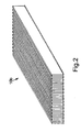
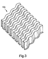
- the fin configuration may be any suitable fin configuration, such as, for example, fin 10a of Fig. 1 which illustrates lanced and offset convoluted fin; fin 10b of Fig.
- fin 10c of Fig. 3 which illustrates ruffled convoluted fin
- Fin manufactured by Robinson Fin Machines, and suitable for application in the cold plate design of the present invention can include any plain, ruffled, or louvered fin, with any manufacturable offset or crest configuration.
- the fin is available in a variety of materials suitable for heat transfer applications such as copper and aluminum.
- the particular fin configuration for each application can be selected based on the allowable pressure drop and required two phase heat transfer coefficient of the particular cooling system.
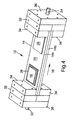
- a cooling system 12 uses fin 10, such as fin 10a, 10b, or 10c, in any of a number of configurations to construct a cold plate 14, for efficiently transferring heat.
- the cooling system 12 uses a vaporizable refrigerant directed through the system 12 in the direction of arrow 16 as the fluid medium to remove heat from components or devices 18 mounted on, or otherwise in thermal contact with, the surface 20 of cold plate 14.
- Figs. 4 and 5 refrigerant enters the system 12 at a refrigerant inlet 22, and exits the system 12 at a refrigerant outlet 24.
- the refrigerant is evaporating as it flows through the cold plate
- Fig. 4 illustrates the completed cold plate 14 assembly.
- a heat generating electrical or electronic component 18 is shown as being mounted to a flat area 26 on surface 20 of the cold plate 14.
- the actual means for mounting or attaching the components 18 to the cold plate 14 can be any suitable means which put the components 18 in thermal contact with the cold plate 14, such as but not limited to thermally conductive adhesive, bolting, clips, clamping, or other mechanical means, and soldering.
- Fig. 5 there is illustrated a partially exploded view of the cold plate 14 assembly of Fig. 4.
- the refrigerant inlet 22 and outlet 24 are shown, as well as a liquid refrigerant distribution means 28.
- the liquid refrigerant distribution means 28 comprises a plurality of grooves or channels 30, formed in member 32 of assembly 12.
- the arrangement of the flow channels 30 are intended to enhance the introduction of the fluid medium to the fin contiguration. Therefore, the arrangement can vary, depending on the size and type of fin used, and the heat transfer requirements of the particular system.
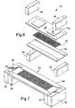
- Fig. 6 illustrates an exploded view of the cold plate body 14 with the fin 10 visible.
- the assembly 12 is designed to be brazed, so that the fin 10 becomes integral with and a part of the structural support of top and bottom plates 14a and 14b, respectively.
- the fin 10 is in intimate heat transfer contact with both plates 14a and 14b, Members 34 can be used to hold the plates 14a and 14b together, maintaining the fin 10 in heat transfer contact with the plates.
- Fig. 7 is a cutaway view showing the liquid refrigerant distribution means 28 and the fin 10 sitting on bottom plate 14b. Also shown is the transition from channels 30 to a tube type structure for allowing the refrigerant to exit the cold plate via outlet 24 of Figs. 4 and 5.
- the cold plate with the fin as best illustrated in Figs. 6 and 7, allows distribution of liquid refrigerant into the flow channels 30, to evenly distribute the liquid throughout the fin 10 configuration. This prevents the formation of hot spots and pressure spikes during the cooling process.
- the present invention does not need to increase the temperature of the cooling fluid to dissipate heat; rather, the heat generated by components 18 is absorbed, causing the refrigerant to boil, and turning the refrigerant from a liquid to a gas.
- FIG. 8 there is illustrated a view of one end of the cold plate assembly 12.
- Fin 10 is inserted between the top and bottom plates 14a and 14b, respectively, and members 34 hold the plates 14a and 14b together.
- Members 32 introduce the flow channels 30 to the system 12, to directionally affect the flow of refrigerant to the fin 10.
- members 36 retain the inlet 22 and the outlet 24, in fluid relationship with the flow channels 30.
- the sections or members 32, 34 and 36 are sealed by O-rings 38, and external connections are made.
- the cold plate assembly 12 has been designed to use a fluorocarbon refrigerant, R-134a, which is non-toxic and has thermo physical properties particularly suitable for cooling applications, such as latent heat of vaporization, vapor pressure and compatibility with common materials of construction.
- R-134a fluorocarbon refrigerant
- many other refrigerants may be used, depending on the specific thermal requirements of the system. These may include, but are not limited to, R-12, R-22, R-401a, R-401c, R-410a, R-508a, HP-80 and MP-39.
- the present invention introduces a vaporizable refrigerant to fin integrally associated with a cold plate to achieve benefits not previously realized with existing systems.
- the refrigerant may either completely or only partially evaporate, depending on the system heat load generated, as it flows through the cold plate.
- the heat transport mechanism is the evaporation of refrigerant removing heat from a surface where the components or devices are mounted.
- the improved cold plate cooling system of the present invention therefore, comprises at least one component that is generating heat and is required to be cooled.
- the cold plate is in thermal contact with the component(s), which cold plate has a fin configuration integral thereto.
- the fin configuration provides cooling across an entire desired area.
- the vaporizable refrigerant is circulated to the cold plate through the fin configuration, whereby the cold plate operates as an evaporator causing the vaporizable refrigerant to at least partially vaporize and remove heat generated by the component(s) from a surface of the cold plate.
- the fin configuration is located to control liquid-gas two phase flow of the vaporizable refrigerant.
- a refrigerant inlet and a refrigerant outlet are associated with the cold plate and the fin configuration
- a liquid form of the vaporizable refrigerant enters the cooling system at the inlet and passes through the fin configuration, turning to vapor as heat is removed from the component and leaving as vapor or a mixture of liquid and vapor.
- the use of offset strip fin or convoluted fin as the evaporating surface allows the cold plate to be cooled uniformly over the entire surface, unlike cold plates with tubes mounted to flat surfaces where thermal spreading is a consideration.
- the use of fin in a cold plate evaporator, as taught by the subject invention, allows for the mounting of components almost anywhere on the cold plate, since nearly the entire surface of the cold plate is uniformly cooled.
Landscapes
- Engineering & Computer Science (AREA)
- Physics & Mathematics (AREA)
- Thermal Sciences (AREA)
- Mechanical Engineering (AREA)
- General Engineering & Computer Science (AREA)
- Cooling Or The Like Of Electrical Apparatus (AREA)
- Cooling Or The Like Of Semiconductors Or Solid State Devices (AREA)
- Details Of Measuring And Other Instruments (AREA)
Abstract
Description
Claims (10)
- An improved cold plate cooling system comprising:at least one component generating heat and required to be cooled;a cold plate in thermal contact with the at least one component to be cooled;a fin configuration integral with the cold plate;a vaporizable refrigerant circulated to the cold plate through the fin configuration, whereby the cold plate operates as an evaporator causing the vaporizable refrigerant to at least partially vaporize and remove heat generated by the at least one component from a surface of the cold plate.
- An improved cooling system as claimed in claim 1 further comprising a refrigerant inlet and a refrigerant outlet associated with the cold plate and the fin configuration whereby a liquid form of the vaporizable refrigerant enters the cooling system at the inlet and passes through the fin configuration, turning to vapor as heat is removed from the component and leaving as vapor or a mixture of liquid and vapor.
- An improved cooling system as claimed in claim 2 further comprising a plurality of flow channels to directionally affect the flow of the vaporizable refrigerant to the fin configuration.
- An improved cooling system as claimed in claim 1 wherein the fin configuration is located to control liquid-gas two phase flow of the vaporizable refrigerant.
- An improved cooling system as claimed in claim 1 wherein the fin configuration provides cooling across an entire desired area.
- A method for cooling one or more electrical or electronic components generating hcat and required to be cooled, the components associated with a cold plate, the method comprising the steps of:locating the cold plate in thermal contact with the one or more electrical or electronic components;integrating a fin configuration into the cold plate;circulating a vaporizable refrigerant to the cold plate through the fin configuration, whereby the cold plate operates as an evaporator causing the vaporizable refrigerant to at least partially vaporize and remove heat generated by the at least one component from a surface of the cold plate.
- A method as claimed in claim 6 further comprising the steps of:providing a refrigerant inlet associated with the cold plate and the tin configuration; andproviding a refrigerant outlet associated with the cold plate and the fin configuration, whereby a liquid form of the vaporizable refrigerant enters at the inlet and passes through the fin configuration, turning to vapor as heat is removed from the component and leaving as vapor or a mixture of liquid and vapor.
- A method as claimed in claim 7 further comprising the step of providing a plurality of flow channels to directionally affect the flow of the vaporizable refrigerant to the fin configuration.
- A method as claimed in claim 6 wherein the fin configuration is located to control liquid-gas two phase flow of the vaporizable refrigerant.
- A method as claimed in claim 6 wherein the fin configuration provides cooling across an entire desired area.
Applications Claiming Priority (2)
| Application Number | Priority Date | Filing Date | Title |
|---|---|---|---|
| US19842400P | 2000-04-19 | 2000-04-19 | |
| US198424P | 2000-04-19 |
Publications (3)
| Publication Number | Publication Date |
|---|---|
| EP1148772A2 true EP1148772A2 (en) | 2001-10-24 |
| EP1148772A3 EP1148772A3 (en) | 2004-01-21 |
| EP1148772B1 EP1148772B1 (en) | 2009-12-23 |
Family
ID=22733326
Family Applications (1)
| Application Number | Title | Priority Date | Filing Date |
|---|---|---|---|
| EP01303503A Expired - Lifetime EP1148772B1 (en) | 2000-04-19 | 2001-04-17 | Cold plate utilizing fin with evaporating refrigerant |
Country Status (5)
| Country | Link |
|---|---|
| US (1) | US6508301B2 (en) |
| EP (1) | EP1148772B1 (en) |
| JP (1) | JP2002107023A (en) |
| CA (1) | CA2344319C (en) |
| DE (1) | DE60140837D1 (en) |
Cited By (3)
| Publication number | Priority date | Publication date | Assignee | Title |
|---|---|---|---|---|
| WO2006108796A1 (en) * | 2005-04-15 | 2006-10-19 | INSTITUT FüR MIKROTECHNIK MAINZ GMBH | Micro-evaporator |
| EP1519646A3 (en) * | 2003-09-26 | 2007-09-26 | Thermal Form & Function LLC | Use of graphite foam materials in pumped liquid, two phase cooling, cold plates |
| DE112008000040B4 (en) * | 2007-01-26 | 2013-12-12 | Aisin Aw Co., Ltd. | Cooling structure of a heat sink for a heat generating component and drive unit |
Families Citing this family (79)
| Publication number | Priority date | Publication date | Assignee | Title |
|---|---|---|---|---|
| US20020186538A1 (en) * | 2001-06-08 | 2002-12-12 | Hiroaki Kase | Cooling module and the system using the same |
| US6819561B2 (en) * | 2002-02-22 | 2004-11-16 | Satcon Technology Corporation | Finned-tube heat exchangers and cold plates, self-cooling electronic component systems using same, and methods for cooling electronic components using same |
| US6889509B1 (en) | 2002-09-13 | 2005-05-10 | Isothermal Systems Research Inc. | Coolant recovery system |
| US20050211417A1 (en) * | 2002-11-01 | 2005-09-29 | Cooligy,Inc. | Interwoven manifolds for pressure drop reduction in microchannel heat exchangers |
| JP2006522463A (en) * | 2002-11-01 | 2006-09-28 | クーリギー インコーポレイテッド | Optimal spreader system, apparatus and method for micro heat exchange cooled by fluid |
| US20040112571A1 (en) * | 2002-11-01 | 2004-06-17 | Cooligy, Inc. | Method and apparatus for efficient vertical fluid delivery for cooling a heat producing device |
| US7156159B2 (en) * | 2003-03-17 | 2007-01-02 | Cooligy, Inc. | Multi-level microchannel heat exchangers |
| US20050211418A1 (en) * | 2002-11-01 | 2005-09-29 | Cooligy, Inc. | Method and apparatus for efficient vertical fluid delivery for cooling a heat producing device |
| US7836597B2 (en) | 2002-11-01 | 2010-11-23 | Cooligy Inc. | Method of fabricating high surface to volume ratio structures and their integration in microheat exchangers for liquid cooling system |
| US20050211427A1 (en) * | 2002-11-01 | 2005-09-29 | Cooligy, Inc. | Method and apparatus for flexible fluid delivery for cooling desired hot spots in a heat producing device |
| US7201012B2 (en) * | 2003-01-31 | 2007-04-10 | Cooligy, Inc. | Remedies to prevent cracking in a liquid system |
| US20090044928A1 (en) * | 2003-01-31 | 2009-02-19 | Girish Upadhya | Method and apparatus for preventing cracking in a liquid cooling system |
| US20040233639A1 (en) * | 2003-01-31 | 2004-11-25 | Cooligy, Inc. | Removeable heat spreader support mechanism and method of manufacturing thereof |
| US7293423B2 (en) * | 2004-06-04 | 2007-11-13 | Cooligy Inc. | Method and apparatus for controlling freezing nucleation and propagation |
| US20040182551A1 (en) * | 2003-03-17 | 2004-09-23 | Cooligy, Inc. | Boiling temperature design in pumped microchannel cooling loops |
| US20050039888A1 (en) * | 2003-08-21 | 2005-02-24 | Pfahnl Andreas C. | Two-phase cooling apparatus and method for automatic test equipment |
| JP2007514121A (en) | 2003-12-05 | 2007-05-31 | リーバート・コーポレイシヨン | Cooling system for high density heat load |
| DE102004059963A1 (en) * | 2003-12-18 | 2005-08-11 | Denso Corp., Kariya | Simply assembled radiator |
| US7017655B2 (en) | 2003-12-18 | 2006-03-28 | Modine Manufacturing Co. | Forced fluid heat sink |
| DE10359806A1 (en) * | 2003-12-19 | 2005-07-14 | Modine Manufacturing Co., Racine | Heat exchanger with flat tubes and flat heat exchanger tube |
| US7616444B2 (en) | 2004-06-04 | 2009-11-10 | Cooligy Inc. | Gimballed attachment for multiple heat exchangers |
| US7188662B2 (en) * | 2004-06-04 | 2007-03-13 | Cooligy, Inc. | Apparatus and method of efficient fluid delivery for cooling a heat producing device |
| US20060042785A1 (en) * | 2004-08-27 | 2006-03-02 | Cooligy, Inc. | Pumped fluid cooling system and method |
| JP2006093637A (en) * | 2004-09-24 | 2006-04-06 | Thermal Form & Function Llc | Improved cold plate structure |
| JP2006286767A (en) * | 2005-03-31 | 2006-10-19 | Hitachi Ltd | Cooling jacket |
| TW200809477A (en) * | 2006-03-30 | 2008-02-16 | Cooligy Inc | Integrated fluid pump and radiator reservoir |
| US7715194B2 (en) * | 2006-04-11 | 2010-05-11 | Cooligy Inc. | Methodology of cooling multiple heat sources in a personal computer through the use of multiple fluid-based heat exchanging loops coupled via modular bus-type heat exchangers |
| US20070256825A1 (en) * | 2006-05-04 | 2007-11-08 | Conway Bruce R | Methodology for the liquid cooling of heat generating components mounted on a daughter card/expansion card in a personal computer through the use of a remote drive bay heat exchanger with a flexible fluid interconnect |
| US20080006396A1 (en) * | 2006-06-30 | 2008-01-10 | Girish Upadhya | Multi-stage staggered radiator for high performance liquid cooling applications |
| TWM311234U (en) * | 2006-08-02 | 2007-05-01 | Man Zai Ind Co Ltd | Water-cooling base |
| US8424592B2 (en) | 2007-01-23 | 2013-04-23 | Modine Manufacturing Company | Heat exchanger having convoluted fin end and method of assembling the same |
| CN101589286B (en) * | 2007-01-23 | 2011-09-28 | 摩丁制造公司 | Heat exchanger and method |
| US20090250201A1 (en) | 2008-04-02 | 2009-10-08 | Grippe Frank M | Heat exchanger having a contoured insert and method of assembling the same |
| TW200924625A (en) * | 2007-08-07 | 2009-06-01 | Cooligy Inc | Deformable duct guides that accommodate electronic connection lines |
| US7709730B2 (en) * | 2007-09-05 | 2010-05-04 | Skyline Solar, Inc. | Dual trough concentrating solar photovoltaic module |
| WO2009046269A2 (en) | 2007-10-03 | 2009-04-09 | Parker Hannifin Corp. | Fuel cell/battery thermal management system |
| JP4967988B2 (en) * | 2007-10-25 | 2012-07-04 | 株式会社豊田自動織機 | Semiconductor cooling device |
| KR101496493B1 (en) * | 2007-11-26 | 2015-02-26 | 가부시키가이샤 도요다 지도숏키 | Liquid-cooled cooling device |
| US9297571B1 (en) | 2008-03-10 | 2016-03-29 | Liebert Corporation | Device and methodology for the removal of heat from an equipment rack by means of heat exchangers mounted to a door |
| US20090225514A1 (en) * | 2008-03-10 | 2009-09-10 | Adrian Correa | Device and methodology for the removal of heat from an equipment rack by means of heat exchangers mounted to a door |
| US8305760B2 (en) | 2008-05-16 | 2012-11-06 | Parker-Hannifin Corporation | Modular high-power drive stack cooled with vaporizable dielectric fluid |
| US20100038056A1 (en) * | 2008-08-15 | 2010-02-18 | Ellsworth Joseph R | High performance compact heat exchanger |
| USD631004S1 (en) | 2008-09-04 | 2011-01-18 | Skyline Solar, Inc. | Dual trough concentrating solar photovoltaic module |
| US7796389B2 (en) * | 2008-11-26 | 2010-09-14 | General Electric Company | Method and apparatus for cooling electronics |
| US20100163014A1 (en) * | 2008-12-29 | 2010-07-01 | Skyline Solar, Inc. | High ground cover ratio solar collection system |
| US8049150B2 (en) * | 2009-01-12 | 2011-11-01 | Skyline Solar, Inc. | Solar collector with end modifications |
| US8844609B2 (en) * | 2009-03-11 | 2014-09-30 | Alcatel Lucent | Cooling manifold |
| WO2011014690A2 (en) * | 2009-07-30 | 2011-02-03 | Skyline Solar, Inc. | Solar energy collection system |
| US20110079376A1 (en) * | 2009-10-03 | 2011-04-07 | Wolverine Tube, Inc. | Cold plate with pins |
| US20110132457A1 (en) * | 2009-12-04 | 2011-06-09 | Skyline Solar, Inc. | Concentrating solar collector with shielding mirrors |
| US20110232877A1 (en) * | 2010-03-23 | 2011-09-29 | Celsia Technologies Taiwan, Inc. | Compact vapor chamber and heat-dissipating module having the same |
| US20110232866A1 (en) * | 2010-03-29 | 2011-09-29 | Zaffetti Mark A | Integral cold plate and honeycomb facesheet assembly |
| JP5545260B2 (en) * | 2010-05-21 | 2014-07-09 | 株式会社デンソー | Heat exchanger |
| US20140041840A1 (en) * | 2012-08-09 | 2014-02-13 | Cooper-Standard Automotive, Inc. | Oil cooler |
| US9363930B2 (en) * | 2013-03-11 | 2016-06-07 | Teco-Westinghouse Motor Company | Passive two phase cooling solution for low, medium and high voltage drive systems |
| CN103234378B (en) * | 2013-04-23 | 2015-09-30 | 东莞汉旭五金塑胶科技有限公司 | Waveform radiating fin and radiator thereof |
| US9439325B2 (en) | 2013-10-21 | 2016-09-06 | International Business Machines Corporation | Coolant-cooled heat sink configured for accelerating coolant flow |
| US9357674B2 (en) | 2013-12-18 | 2016-05-31 | International Business Machines Corporation | Liquid-cooling apparatus with integrated coolant filter |
| JP6247090B2 (en) * | 2013-12-26 | 2017-12-13 | 昭和電工株式会社 | Liquid cooling type cooling device and manufacturing method of radiator for liquid cooling type cooling device |
| US9537686B2 (en) * | 2014-04-03 | 2017-01-03 | Redline Communications Inc. | Systems and methods for increasing the effectiveness of digital pre-distortion in electronic communications |
| US10178805B2 (en) * | 2014-05-23 | 2019-01-08 | Tesla, Inc. | Heatsink with internal cavity for liquid cooling |
| US20160118700A1 (en) * | 2014-10-24 | 2016-04-28 | Ford Global Technologies, Llc | Traction battery thermal management |
| US9819062B2 (en) | 2014-11-14 | 2017-11-14 | Ford Global Technologies, Llc | Traction battery assembly with thermal device |
| CN105806134A (en) * | 2014-12-29 | 2016-07-27 | 中国兵器装备研究院 | Water cooling plate |
| KR101706263B1 (en) * | 2015-04-16 | 2017-02-15 | 서울시립대학교 산학협력단 | Wavy fin, heat exchanger having the same, apparatus for manufacturing the same, method for manufacturing the same and computer recordable medium storing the method |
| EP3249686B1 (en) * | 2016-05-24 | 2025-02-12 | Mitsubishi Electric R&D Centre Europe B.V. | A power module |
| DE102017001567B4 (en) * | 2017-02-20 | 2022-06-09 | Diehl Aerospace Gmbh | Evaporator and fuel cell assembly |
| US10888024B1 (en) | 2017-08-28 | 2021-01-05 | Equinix, Inc. | Data center refrigeration system |
| US12004329B1 (en) | 2017-08-28 | 2024-06-04 | Equinix, Inc. | Data center refrigeration system |
| US10527365B1 (en) * | 2018-07-09 | 2020-01-07 | International Business Machines Corporation | Disconnect assembly for active cooling of packaged electronics |
| CN111336718A (en) * | 2019-08-30 | 2020-06-26 | 同方节能工程技术有限公司 | Heat pipe type absorption heat exchanger unit |
| DE112021004801T5 (en) * | 2020-09-14 | 2023-07-27 | T.Rad Co., Ltd. | HEAT EXCHANGER |
| US11924996B2 (en) * | 2020-09-30 | 2024-03-05 | Coolit Systems, Inc. | Liquid-cooling devices, and systems, to cool multi-chip modules |
| CN112414199B (en) * | 2020-11-24 | 2021-12-03 | 浙江银轮机械股份有限公司 | Heat dissipation fin construction method and related device and heat dissipation fin |
| US12215933B2 (en) | 2020-11-30 | 2025-02-04 | Dana Canada Corporation | Compact heat exchanger with wavy fin turbulizer |
| US11968803B2 (en) * | 2021-12-22 | 2024-04-23 | Baidu Usa Llc | Two phase immersion system with local fluid accelerations |
| JP2023154856A (en) * | 2022-04-08 | 2023-10-20 | ニデック株式会社 | Liquid cooling jacket and cooling device |
| US20240175645A1 (en) * | 2022-11-30 | 2024-05-30 | Valeo Systemes Thermiques | Attachment for a heat exchanger |
| CN118960314B (en) * | 2024-10-16 | 2025-03-04 | 浪潮电子信息产业股份有限公司 | Liquid cooling device and liquid cooling device testing method |
Family Cites Families (16)
| Publication number | Priority date | Publication date | Assignee | Title |
|---|---|---|---|---|
| FR1319387A (en) * | 1962-01-17 | 1963-03-01 | Chausson Usines Sa | Method and device for cooling semiconductor elements, in particular transistors |
| US3327776A (en) * | 1965-10-24 | 1967-06-27 | Trane Co | Heat exchanger |
| DE2102254B2 (en) | 1971-01-19 | 1973-05-30 | Robert Bosch Gmbh, 7000 Stuttgart | COOLING DEVICE FOR POWER SEMICONDUCTOR COMPONENTS |
| GB1484831A (en) * | 1975-03-17 | 1977-09-08 | Hughes Aircraft Co | Heat pipe thermal mounting plate for cooling circuit card-mounted electronic components |
| US4072188A (en) * | 1975-07-02 | 1978-02-07 | Honeywell Information Systems Inc. | Fluid cooling systems for electronic systems |
| JPH07114250B2 (en) * | 1990-04-27 | 1995-12-06 | インターナショナル・ビジネス・マシーンズ・コーポレイション | Heat transfer system |
| DE4131739C2 (en) * | 1991-09-24 | 1996-12-19 | Behr Industrietech Gmbh & Co | Cooling device for electrical components |
| JPH06164172A (en) * | 1992-11-16 | 1994-06-10 | Mitsubishi Electric Corp | Cooling plate |
| FR2701554B1 (en) * | 1993-02-12 | 1995-05-12 | Transcal | Heat exchanger for electronic components and electro-technical equipment. |
| JP3158983B2 (en) * | 1994-10-03 | 2001-04-23 | 住友精密工業株式会社 | Corrugated radiator fin for cooling LSI package |
| JP3487382B2 (en) | 1994-12-28 | 2004-01-19 | 株式会社デンソー | Boiling cooling device |
| US5737923A (en) * | 1995-10-17 | 1998-04-14 | Marlow Industries, Inc. | Thermoelectric device with evaporating/condensing heat exchanger |
| US6305463B1 (en) * | 1996-02-22 | 2001-10-23 | Silicon Graphics, Inc. | Air or liquid cooled computer module cold plate |
| JPH11204978A (en) * | 1998-01-12 | 1999-07-30 | Mitsubishi Electric Corp | Electronics |
| JP3997594B2 (en) * | 1998-03-10 | 2007-10-24 | ダイキン工業株式会社 | Air-cooled absorber |
| JP2000105089A (en) * | 1998-07-31 | 2000-04-11 | Sanden Corp | Heat exchanger |
-
2001
- 2001-04-17 EP EP01303503A patent/EP1148772B1/en not_active Expired - Lifetime
- 2001-04-17 DE DE60140837T patent/DE60140837D1/en not_active Expired - Lifetime
- 2001-04-17 US US09/836,023 patent/US6508301B2/en not_active Expired - Lifetime
- 2001-04-18 CA CA2344319A patent/CA2344319C/en not_active Expired - Fee Related
- 2001-04-18 JP JP2001119378A patent/JP2002107023A/en active Pending
Cited By (4)
| Publication number | Priority date | Publication date | Assignee | Title |
|---|---|---|---|---|
| EP1519646A3 (en) * | 2003-09-26 | 2007-09-26 | Thermal Form & Function LLC | Use of graphite foam materials in pumped liquid, two phase cooling, cold plates |
| WO2006108796A1 (en) * | 2005-04-15 | 2006-10-19 | INSTITUT FüR MIKROTECHNIK MAINZ GMBH | Micro-evaporator |
| US8167030B2 (en) | 2005-04-15 | 2012-05-01 | Gunther Kolb | Micro-evaporator |
| DE112008000040B4 (en) * | 2007-01-26 | 2013-12-12 | Aisin Aw Co., Ltd. | Cooling structure of a heat sink for a heat generating component and drive unit |
Also Published As
| Publication number | Publication date |
|---|---|
| CA2344319C (en) | 2010-03-23 |
| EP1148772B1 (en) | 2009-12-23 |
| DE60140837D1 (en) | 2010-02-04 |
| US20020007935A1 (en) | 2002-01-24 |
| EP1148772A3 (en) | 2004-01-21 |
| CA2344319A1 (en) | 2001-10-19 |
| JP2002107023A (en) | 2002-04-10 |
| US6508301B2 (en) | 2003-01-21 |
Similar Documents
| Publication | Publication Date | Title |
|---|---|---|
| US6508301B2 (en) | Cold plate utilizing fin with evaporating refrigerant | |
| US6845622B2 (en) | Phase-change refrigeration apparatus with thermoelectric cooling element and methods | |
| EP1143778B1 (en) | Pumped liquid cooling system using a phase change refrigerant | |
| US7077189B1 (en) | Liquid cooled thermosiphon with flexible coolant tubes | |
| US5737923A (en) | Thermoelectric device with evaporating/condensing heat exchanger | |
| EP1519646A2 (en) | Use of graphite foam materials in pumped liquid, two phase cooling, cold plates | |
| US8833435B2 (en) | Microscale cooling apparatus and method | |
| US20180080685A1 (en) | Microelectronics cooling system | |
| US20060162903A1 (en) | Liquid cooled thermosiphon with flexible partition | |
| AU2008343788B2 (en) | Heat pipes incorporating microchannel heat exchangers | |
| CN111818756B (en) | Heat exchanger with integrated two-phase radiator | |
| US20070230128A1 (en) | Cooling apparatus with surface enhancement boiling heat transfer | |
| US20100326627A1 (en) | Microelectronics cooling system | |
| EP2203696A1 (en) | Topping cycle for a sub-ambient cooling system | |
| US20050005623A1 (en) | Pumped liquid cooling system using a phase change refrigerant | |
| WO2010096355A2 (en) | Cooling system utilizing multiple cold plates | |
| US11859912B2 (en) | Microelectronics cooling system | |
| US10907910B2 (en) | Vapor-liquid phase fluid heat transfer module | |
| US10578368B2 (en) | Two-phase fluid heat transfer structure | |
| CN214581473U (en) | Radiator and air condensing units | |
| TW202303070A (en) | Radiator for heat element | |
| WO2018182452A1 (en) | Heat-transfer device for cooling electronic components | |
| JP2006093637A (en) | Improved cold plate structure | |
| WO2000011423A1 (en) | Heat exchanger for conducting elsewhere heat energy generated by heat source |
Legal Events
| Date | Code | Title | Description |
|---|---|---|---|
| PUAI | Public reference made under article 153(3) epc to a published international application that has entered the european phase |
Free format text: ORIGINAL CODE: 0009012 |
|
| AK | Designated contracting states |
Kind code of ref document: A2 Designated state(s): AT BE CH CY DE DK ES FI FR GB GR IE IT LI LU MC NL PT SE TR |
|
| AX | Request for extension of the european patent |
Free format text: AL;LT;LV;MK;RO;SI |
|
| PUAL | Search report despatched |
Free format text: ORIGINAL CODE: 0009013 |
|
| AK | Designated contracting states |
Kind code of ref document: A3 Designated state(s): AT BE CH CY DE DK ES FI FR GB GR IE IT LI LU MC NL PT SE TR |
|
| AX | Request for extension of the european patent |
Extension state: AL LT LV MK RO SI |
|
| 17P | Request for examination filed |
Effective date: 20040705 |
|
| AKX | Designation fees paid |
Designated state(s): DE FR GB IT |
|
| 17Q | First examination report despatched |
Effective date: 20041005 |
|
| 17Q | First examination report despatched |
Effective date: 20041005 |
|
| RAP1 | Party data changed (applicant data changed or rights of an application transferred) |
Owner name: THERMAL FORM & FUNCTION INC. |
|
| GRAP | Despatch of communication of intention to grant a patent |
Free format text: ORIGINAL CODE: EPIDOSNIGR1 |
|
| GRAS | Grant fee paid |
Free format text: ORIGINAL CODE: EPIDOSNIGR3 |
|
| GRAA | (expected) grant |
Free format text: ORIGINAL CODE: 0009210 |
|
| AK | Designated contracting states |
Kind code of ref document: B1 Designated state(s): DE FR GB IT |
|
| REG | Reference to a national code |
Ref country code: GB Ref legal event code: FG4D |
|
| REF | Corresponds to: |
Ref document number: 60140837 Country of ref document: DE Date of ref document: 20100204 Kind code of ref document: P |
|
| PLBE | No opposition filed within time limit |
Free format text: ORIGINAL CODE: 0009261 |
|
| STAA | Information on the status of an ep patent application or granted ep patent |
Free format text: STATUS: NO OPPOSITION FILED WITHIN TIME LIMIT |
|
| 26N | No opposition filed |
Effective date: 20100924 |
|
| REG | Reference to a national code |
Ref country code: FR Ref legal event code: PLFP Year of fee payment: 16 |
|
| PGFP | Annual fee paid to national office [announced via postgrant information from national office to epo] |
Ref country code: FR Payment date: 20160323 Year of fee payment: 16 |
|
| PGFP | Annual fee paid to national office [announced via postgrant information from national office to epo] |
Ref country code: DE Payment date: 20160412 Year of fee payment: 16 Ref country code: GB Payment date: 20160413 Year of fee payment: 16 |
|
| PGFP | Annual fee paid to national office [announced via postgrant information from national office to epo] |
Ref country code: IT Payment date: 20160418 Year of fee payment: 16 |
|
| REG | Reference to a national code |
Ref country code: DE Ref legal event code: R119 Ref document number: 60140837 Country of ref document: DE |
|
| GBPC | Gb: european patent ceased through non-payment of renewal fee |
Effective date: 20170417 |
|
| REG | Reference to a national code |
Ref country code: FR Ref legal event code: ST Effective date: 20171229 |
|
| PG25 | Lapsed in a contracting state [announced via postgrant information from national office to epo] |
Ref country code: DE Free format text: LAPSE BECAUSE OF NON-PAYMENT OF DUE FEES Effective date: 20171103 Ref country code: FR Free format text: LAPSE BECAUSE OF NON-PAYMENT OF DUE FEES Effective date: 20170502 |
|
| PG25 | Lapsed in a contracting state [announced via postgrant information from national office to epo] |
Ref country code: GB Free format text: LAPSE BECAUSE OF NON-PAYMENT OF DUE FEES Effective date: 20170417 |
|
| PG25 | Lapsed in a contracting state [announced via postgrant information from national office to epo] |
Ref country code: IT Free format text: LAPSE BECAUSE OF NON-PAYMENT OF DUE FEES Effective date: 20170417 |