EP1148770A2 - Générateur de plasma pour la chirurgie HF - Google Patents
Générateur de plasma pour la chirurgie HF Download PDFInfo
- Publication number
- EP1148770A2 EP1148770A2 EP01104487A EP01104487A EP1148770A2 EP 1148770 A2 EP1148770 A2 EP 1148770A2 EP 01104487 A EP01104487 A EP 01104487A EP 01104487 A EP01104487 A EP 01104487A EP 1148770 A2 EP1148770 A2 EP 1148770A2
- Authority
- EP
- European Patent Office
- Prior art keywords
- handpiece
- power
- plasma generator
- resonance
- frequency
- Prior art date
- Legal status (The legal status is an assumption and is not a legal conclusion. Google has not performed a legal analysis and makes no representation as to the accuracy of the status listed.)
- Withdrawn
Links
- 238000001356 surgical procedure Methods 0.000 title description 13
- 239000003990 capacitor Substances 0.000 claims abstract description 40
- 238000004804 winding Methods 0.000 claims description 42
- 230000005495 cold plasma Effects 0.000 claims description 8
- 210000001519 tissue Anatomy 0.000 description 37
- 239000007789 gas Substances 0.000 description 36
- 230000015271 coagulation Effects 0.000 description 18
- 238000005345 coagulation Methods 0.000 description 18
- 239000002184 metal Substances 0.000 description 13
- 229910052751 metal Inorganic materials 0.000 description 13
- 239000004020 conductor Substances 0.000 description 12
- 210000004027 cell Anatomy 0.000 description 8
- 238000010276 construction Methods 0.000 description 8
- 239000001307 helium Substances 0.000 description 8
- 229910052734 helium Inorganic materials 0.000 description 8
- SWQJXJOGLNCZEY-UHFFFAOYSA-N helium atom Chemical compound [He] SWQJXJOGLNCZEY-UHFFFAOYSA-N 0.000 description 8
- 230000008901 benefit Effects 0.000 description 7
- XKRFYHLGVUSROY-UHFFFAOYSA-N Argon Chemical compound [Ar] XKRFYHLGVUSROY-UHFFFAOYSA-N 0.000 description 6
- 230000006378 damage Effects 0.000 description 6
- 229910000859 α-Fe Inorganic materials 0.000 description 6
- 238000010891 electric arc Methods 0.000 description 5
- 238000001839 endoscopy Methods 0.000 description 5
- 230000005284 excitation Effects 0.000 description 5
- 230000006698 induction Effects 0.000 description 5
- 239000004033 plastic Substances 0.000 description 5
- 238000006073 displacement reaction Methods 0.000 description 4
- 230000000694 effects Effects 0.000 description 4
- 238000010438 heat treatment Methods 0.000 description 4
- 238000001465 metallisation Methods 0.000 description 4
- 230000007935 neutral effect Effects 0.000 description 4
- RYGMFSIKBFXOCR-UHFFFAOYSA-N Copper Chemical compound [Cu] RYGMFSIKBFXOCR-UHFFFAOYSA-N 0.000 description 3
- 229910052786 argon Inorganic materials 0.000 description 3
- 239000000919 ceramic Substances 0.000 description 3
- 238000010586 diagram Methods 0.000 description 3
- 238000005516 engineering process Methods 0.000 description 3
- 239000012530 fluid Substances 0.000 description 3
- 230000001939 inductive effect Effects 0.000 description 3
- 238000000034 method Methods 0.000 description 3
- 230000035515 penetration Effects 0.000 description 3
- 230000009467 reduction Effects 0.000 description 3
- 206010039509 Scab Diseases 0.000 description 2
- 210000000170 cell membrane Anatomy 0.000 description 2
- 238000013461 design Methods 0.000 description 2
- 239000003814 drug Substances 0.000 description 2
- 239000004744 fabric Substances 0.000 description 2
- 230000007274 generation of a signal involved in cell-cell signaling Effects 0.000 description 2
- 239000007788 liquid Substances 0.000 description 2
- 238000005259 measurement Methods 0.000 description 2
- 238000012544 monitoring process Methods 0.000 description 2
- 102000004169 proteins and genes Human genes 0.000 description 2
- 108090000623 proteins and genes Proteins 0.000 description 2
- YSUIQYOGTINQIN-UZFYAQMZSA-N 2-amino-9-[(1S,6R,8R,9S,10R,15R,17R,18R)-8-(6-aminopurin-9-yl)-9,18-difluoro-3,12-dihydroxy-3,12-bis(sulfanylidene)-2,4,7,11,13,16-hexaoxa-3lambda5,12lambda5-diphosphatricyclo[13.2.1.06,10]octadecan-17-yl]-1H-purin-6-one Chemical compound NC1=NC2=C(N=CN2[C@@H]2O[C@@H]3COP(S)(=O)O[C@@H]4[C@@H](COP(S)(=O)O[C@@H]2[C@@H]3F)O[C@H]([C@H]4F)N2C=NC3=C2N=CN=C3N)C(=O)N1 YSUIQYOGTINQIN-UZFYAQMZSA-N 0.000 description 1
- QBWKPGNFQQJGFY-QLFBSQMISA-N 3-[(1r)-1-[(2r,6s)-2,6-dimethylmorpholin-4-yl]ethyl]-n-[6-methyl-3-(1h-pyrazol-4-yl)imidazo[1,2-a]pyrazin-8-yl]-1,2-thiazol-5-amine Chemical compound N1([C@H](C)C2=NSC(NC=3C4=NC=C(N4C=C(C)N=3)C3=CNN=C3)=C2)C[C@H](C)O[C@H](C)C1 QBWKPGNFQQJGFY-QLFBSQMISA-N 0.000 description 1
- XDTMQSROBMDMFD-UHFFFAOYSA-N C1CCCCC1 Chemical compound C1CCCCC1 XDTMQSROBMDMFD-UHFFFAOYSA-N 0.000 description 1
- 230000001133 acceleration Effects 0.000 description 1
- 230000009471 action Effects 0.000 description 1
- QVGXLLKOCUKJST-UHFFFAOYSA-N atomic oxygen Chemical compound [O] QVGXLLKOCUKJST-UHFFFAOYSA-N 0.000 description 1
- 230000005540 biological transmission Effects 0.000 description 1
- 239000008280 blood Substances 0.000 description 1
- 210000004369 blood Anatomy 0.000 description 1
- 210000004204 blood vessel Anatomy 0.000 description 1
- 238000009835 boiling Methods 0.000 description 1
- 210000004556 brain Anatomy 0.000 description 1
- 210000002421 cell wall Anatomy 0.000 description 1
- 230000008859 change Effects 0.000 description 1
- 230000000739 chaotic effect Effects 0.000 description 1
- 239000002800 charge carrier Substances 0.000 description 1
- 238000006243 chemical reaction Methods 0.000 description 1
- 238000002485 combustion reaction Methods 0.000 description 1
- 229940125846 compound 25 Drugs 0.000 description 1
- 238000001816 cooling Methods 0.000 description 1
- 239000011889 copper foil Substances 0.000 description 1
- 230000008878 coupling Effects 0.000 description 1
- 238000010168 coupling process Methods 0.000 description 1
- 238000005859 coupling reaction Methods 0.000 description 1
- 230000000254 damaging effect Effects 0.000 description 1
- 230000018044 dehydration Effects 0.000 description 1
- 238000006297 dehydration reaction Methods 0.000 description 1
- 238000011161 development Methods 0.000 description 1
- 238000002845 discoloration Methods 0.000 description 1
- 201000010099 disease Diseases 0.000 description 1
- 208000037265 diseases, disorders, signs and symptoms Diseases 0.000 description 1
- 230000005672 electromagnetic field Effects 0.000 description 1
- 230000005674 electromagnetic induction Effects 0.000 description 1
- 230000007613 environmental effect Effects 0.000 description 1
- 238000001704 evaporation Methods 0.000 description 1
- 230000008020 evaporation Effects 0.000 description 1
- 230000002349 favourable effect Effects 0.000 description 1
- 239000011888 foil Substances 0.000 description 1
- 238000003780 insertion Methods 0.000 description 1
- 230000037431 insertion Effects 0.000 description 1
- 150000002500 ions Chemical class 0.000 description 1
- 230000007246 mechanism Effects 0.000 description 1
- 230000004048 modification Effects 0.000 description 1
- 238000012986 modification Methods 0.000 description 1
- 210000000944 nerve tissue Anatomy 0.000 description 1
- 239000001301 oxygen Substances 0.000 description 1
- 229910052760 oxygen Inorganic materials 0.000 description 1
- 239000002245 particle Substances 0.000 description 1
- 229920001296 polysiloxane Polymers 0.000 description 1
- 239000004810 polytetrafluoroethylene Substances 0.000 description 1
- 229920001343 polytetrafluoroethylene Polymers 0.000 description 1
- 230000008569 process Effects 0.000 description 1
- 230000001681 protective effect Effects 0.000 description 1
- 239000010453 quartz Substances 0.000 description 1
- 230000018040 scab formation Effects 0.000 description 1
- 230000035939 shock Effects 0.000 description 1
- VYPSYNLAJGMNEJ-UHFFFAOYSA-N silicon dioxide Inorganic materials O=[Si]=O VYPSYNLAJGMNEJ-UHFFFAOYSA-N 0.000 description 1
- 238000005476 soldering Methods 0.000 description 1
- 238000001228 spectrum Methods 0.000 description 1
- 239000007921 spray Substances 0.000 description 1
- 238000012360 testing method Methods 0.000 description 1
- 230000001225 therapeutic effect Effects 0.000 description 1
- 238000012546 transfer Methods 0.000 description 1
Images


Classifications
-
- A—HUMAN NECESSITIES
- A61—MEDICAL OR VETERINARY SCIENCE; HYGIENE
- A61B—DIAGNOSIS; SURGERY; IDENTIFICATION
- A61B18/00—Surgical instruments, devices or methods for transferring non-mechanical forms of energy to or from the body
- A61B18/18—Surgical instruments, devices or methods for transferring non-mechanical forms of energy to or from the body by applying electromagnetic radiation, e.g. microwaves
- A61B18/20—Surgical instruments, devices or methods for transferring non-mechanical forms of energy to or from the body by applying electromagnetic radiation, e.g. microwaves using laser
- A61B18/201—Surgical instruments, devices or methods for transferring non-mechanical forms of energy to or from the body by applying electromagnetic radiation, e.g. microwaves using laser with beam delivery through a hollow tube, e.g. forming an articulated arm ; Hand-pieces therefor
-
- H—ELECTRICITY
- H05—ELECTRIC TECHNIQUES NOT OTHERWISE PROVIDED FOR
- H05H—PLASMA TECHNIQUE; PRODUCTION OF ACCELERATED ELECTRICALLY-CHARGED PARTICLES OR OF NEUTRONS; PRODUCTION OR ACCELERATION OF NEUTRAL MOLECULAR OR ATOMIC BEAMS
- H05H1/00—Generating plasma; Handling plasma
- H05H1/24—Generating plasma
- H05H1/26—Plasma torches
- H05H1/32—Plasma torches using an arc
- H05H1/34—Details, e.g. electrodes, nozzles
- H05H1/36—Circuit arrangements
-
- H—ELECTRICITY
- H05—ELECTRIC TECHNIQUES NOT OTHERWISE PROVIDED FOR
- H05H—PLASMA TECHNIQUE; PRODUCTION OF ACCELERATED ELECTRICALLY-CHARGED PARTICLES OR OF NEUTRONS; PRODUCTION OR ACCELERATION OF NEUTRAL MOLECULAR OR ATOMIC BEAMS
- H05H1/00—Generating plasma; Handling plasma
- H05H1/24—Generating plasma
- H05H1/46—Generating plasma using applied electromagnetic fields, e.g. high frequency or microwave energy
- H05H1/4645—Radiofrequency discharges
- H05H1/466—Radiofrequency discharges using capacitive coupling means, e.g. electrodes
-
- A—HUMAN NECESSITIES
- A61—MEDICAL OR VETERINARY SCIENCE; HYGIENE
- A61B—DIAGNOSIS; SURGERY; IDENTIFICATION
- A61B17/00—Surgical instruments, devices or methods, e.g. tourniquets
- A61B2017/0046—Surgical instruments, devices or methods, e.g. tourniquets with a releasable handle; with handle and operating part separable
-
- A—HUMAN NECESSITIES
- A61—MEDICAL OR VETERINARY SCIENCE; HYGIENE
- A61B—DIAGNOSIS; SURGERY; IDENTIFICATION
- A61B18/00—Surgical instruments, devices or methods for transferring non-mechanical forms of energy to or from the body
- A61B2018/00636—Sensing and controlling the application of energy
- A61B2018/00696—Controlled or regulated parameters
- A61B2018/00702—Power or energy
-
- A—HUMAN NECESSITIES
- A61—MEDICAL OR VETERINARY SCIENCE; HYGIENE
- A61B—DIAGNOSIS; SURGERY; IDENTIFICATION
- A61B18/00—Surgical instruments, devices or methods for transferring non-mechanical forms of energy to or from the body
- A61B2018/00636—Sensing and controlling the application of energy
- A61B2018/00773—Sensed parameters
- A61B2018/00779—Power or energy
-
- H—ELECTRICITY
- H05—ELECTRIC TECHNIQUES NOT OTHERWISE PROVIDED FOR
- H05H—PLASMA TECHNIQUE; PRODUCTION OF ACCELERATED ELECTRICALLY-CHARGED PARTICLES OR OF NEUTRONS; PRODUCTION OR ACCELERATION OF NEUTRAL MOLECULAR OR ATOMIC BEAMS
- H05H2245/00—Applications of plasma devices
- H05H2245/30—Medical applications
- H05H2245/32—Surgery, e.g. scalpels, blades or bistoury; Treatments inside the body
Definitions
- the present invention relates to a plasma generator for generating a cold plasma jets for use in the medical field, in particular for surgical Applications, as well as for other areas of science.
- Plasma sources that under atmospheric pressure have a plasma of more than 1000 degrees can generate are common.
- the plasma is heated by conventional electromagnetic induction, more precisely: through inductive heating of electrically conductive media in the alternating electromagnetic field of an induction coil.
- This plasma source consists of an alternating current high voltage generator, one tubular quartz container and a liquid cooled induction coil with a high number of turns.
- a coil with a diameter of 10 cm is essential required to produce an induction in a volume of 1 liter.
- the induction resistance increases very strongly at frequencies above 1 MHz. Generally is it is difficult to adapt the high voltage generator to the induction resistance, because it reduces the effective output power.
- the development of a plasma source according to the knowledge of technology leads to a reduction in the size of the external Dimensions, but also to lower efficiency and higher plasma temperatures, what, especially in the fields of medicine, biology and environmental applications, limits the area of application.
- Plasma generators are used in electrical discharge devices that with an electronic oscillator, a modulation stage, a resonance transformer and a rod-shaped discharge electrode.
- a plasma beam will generated here between the electrode end and the object.
- the electronic oscillator generates vibrations in the range of approx. 200 to 300 kHz.
- the modulator switches the oscillator signal on and off in a frequency range of 3 to 5 kHz. On in this way, the modulator provides increased excitation of the resonance transmitter and the object.
- This device has a favorable therapeutic effect in the treatment from many diseases by giving heat to different parts of the body feeds.
- HF surgery uses an HF frequency generator for spray coagulation or argon coagulation (plasma discharge within an argon beam).
- the HF generator works according to the principle of shock excitation of oscillating circuits.
- This pulse excitation of an oscillating circuit generates short RF pulses (bursts) with a long interval measured in terms of the pulse duration (see Fig. 2).
- the ratio of pulse duration / pause interval is usually between 10 and 20 percent. This leads to strong peak power during the bursts and consequently to very high peak currents that can reach several amperes. Under these circumstances, the capacity between patient and earth is not sufficient to close the circuit and therefore usually requires the use of a neutral electrode in conventional HF surgery.
- the contact area of the discharge arc on the tissue becomes relatively large and can reach several square millimeters, so that the depth of penetration of the heat effect is felt to be very large.
- current peaks that flow through the tissue lead to a high current load in deeper areas, which can have a damaging effect on sensitive tissue, such as nerve tissue in the brain.
- the spectrum of an HF current which consists of short bursts, always contains a factor that should not be underestimated, which is derived from the pulse repetition frequency. This frequency is usually between 10 and 70 kHz. These low frequencies can damage sensitive tissue.
- Conventional-type plasma generators that generate the plasma inductively or via an arc discharge are too heavy for a handpiece due to their cooling requirements.
- conventional plasma generators generate very high plasma temperatures of several thousand degrees Celsius as heat plasma.
- This generator contains a voltage source and an electrical oscillator, the electrical oscillator being powered by an amplifier connected to a Low voltage device is connected, a resonance transformer with a low voltage input and a high voltage output and a connection of the high voltage output of the resonance transformer with the discharge electrode.
- This oscillator has a feedback winding to which a single-stage power oscillator is connected is. The very low stability of the discharge amplitude and the associated Power control problems are associated with such a single stage Power oscillator disadvantageous.
- U.S. Patent 4,781,175 (issued to McGreevy and others) describes the application an electrosurgical conductive gas jet to improve scab formation for coagulation.
- a predetermined ionizable gas becomes the tissue jet-shaped at a flow rate that is used to remove natural liquids of the tissue and for the disclosure of the tissue flow is sufficient.
- electrical energy is used as arcs in the ionized conductive Areas fed.
- European patent application EP 0787465 A1 (issued to Kim and others) describes a cold plasma coagulator.
- This cold plasma coagulator consists of a High-frequency power supply, a gas dynamic block and a plasmotron.
- the power supply is there consisting of rectifier, capacitor buffer and a voltage inverter.
- a resonance inductor and a non-conductive tube are arranged coaxially, with one end of the non-conductive tube is connected to the gas dynamic block, while the other End ejects plasma through a nozzle.
- the turns of the resonance inductor exist from a low voltage and a high voltage part.
- the low voltage part the resonance coils is connected to the output of the voltage inverter.
- the GDR patent 79087 (issued to G. Pforr) describes a device for operating a inductive plasma torch.
- a high frequency generated by a high frequency generator AC power is supplied to a work coil.
- the work spool is movable and connected to the high frequency generator with a power coaxial cable.
- An inductive plasma flame is generated in the insulating tube of the work coil.
- European patent application 0155496 (issued to Peter Gagne) describes a plasma emission source. It contains an RF power generator, a plasma torch as well as controllers for automatic and constant control of the generator RF energy conducted to the load coil. A tunable series or parallel circuit regulates the impedance of the power generator or the load coil. Every district has at least an adjustable capacitor and devices for controlling the capacitors. These consist of primary and secondary motors for controlling the mentioned Capacitors and a detector for the delivery of input signals that the Reflect the phase relationship of the RF voltage and RF current.
- a handpiece for surgical cuts with a plasma jet is described in U.S. Patent 4,781,175 (issued to Birtcher) and particularly shown in Figures 6 to 9.
- Conventional HF surgical instruments deliver unstable signals with high current peaks of several amperes. Due to the high potential differences between the inside and the outside of the cell membrane, these current peaks of conventional devices can also cause damage in lower tissue areas.
- the present invention is intended to provide a surgical scab Cold plasma jet device are generated as far as possible without charring or Combustion products due to oxygen inclusions are related to this can occur with the argon plasma method.
- the present invention relates to a cold plasma device used in HF surgery used for coagulation of tissue surfaces and for abrasive removal of tissue becomes.
- the cold plasma device described in the present invention contains an HF generator, a resonance transmitter, a handpiece and a helium gas source.
- the device is used for the coagulation of tissue by plasma discharges in the area HF surgery.
- the structure and functions are as follows: an HF generator sends its signal to a resonance transformer.
- the resonance transformer transforms the RF signal from approx. 350 kHz to a voltage of approx. 2000 to 3000 volts.
- the output of this resonance transmitter (Secondary winding) is via a coaxial line with an integrated gas line connected to a handpiece to supply helium.
- the second pole of the secondary winding is grounded.
- the handpiece has an electrode tip that is in a Nozzle is arranged, through and around which the protective gas helium flows. This electrode tip is connected to the conductor of the coaxial line, via a capacitor supplies the RF voltage.
- Corona discharge takes place at the tip of the electrode inside the nozzle.
- the gas flow is driving the corona discharge through the nozzle so that a flame discharge in the Air takes place. If this flame is directed against a tissue, an arc discharge occurs to the tissue that is accompanied by an appropriate arc.
- the height Current density at the point of impact and the acceleration of the charge carriers (ions) immediately at the point of impact of the electric arc cause coagulation as well evaporation of the tissue if the frequency is chosen to be sufficiently high.
- the RF current then flows as a dielectric displacement current from the surface of the Reduce patient weight as long as the patient is not electrically grounded.
- a neutral one Electrode is not used and in this way there is a flow of current through the patient prevented or at least significantly reduced.
- the one built into the handpiece Due to its low capacitance, the capacitor limits the HF current to values below 150 mA and thus keeps the leakage currents below the maximum permissible for HF surgery Values.
- the resonance transmitter is used in contrast to conventional HF surgical devices not excited by impulses, but the excitation of the resonance transmitter takes place constantly. As a result, the resonance transformer generates a pure sine signal without the high current peaks that are common in conventional HF surgical devices of several amperes, and these signals also do not cause any damage to lower tissue areas.
- the cutting effect in HF surgery is based on the principle of cell rupture.
- the achieved Cuts can be described as smooth, rich in coagulation and scabbed.
- a smooth cut in HF surgery is largely achieved with a scalpel Cut comparable, i.e. the cut surfaces are only slightly discolored.
- the cut type The smooth cut is made with an unmodulated HF current and when carried out quickly of the cut.
- a reduction in the cutting speed has a cut with more coagulation or a cut with scab.
- the same result is achieved when a pulse modulated RF current of the same average power is used.
- the power required to perform an RF cut depends on the shape of the Electrode, the type of tissue and its resistance. If the performance is too low, find there is no cell tear and the tissue sticks to the electrode. The performance is too high, spark discharges can occur on the electrode and in the tissue, which is a Charring the cut surfaces results.
- the tissue is more or less heated to the extent that there is no cell tear for the coagulation takes place.
- the coagulation temperature is over 50 ° C. This temperature leads to Coagulation of the cell protein inside and outside the cell by boiling of the fabric. Injured blood vessels contract so far that they are complete be closed and no blood leaks. To achieve this effect, must an electric current heats the tissue slowly enough so that the fluids can be vaporized inside and outside the cell without the cell membranes Get damaged. The cells contract due to the loss of fluid and the cell walls are welded together.
- This type of coagulation is common Contact coagulation is called because the electrodes are in direct contact with the tissue to be brought. A supply of HF current causes a slight discoloration of the tissue as well as an outflow of tissue fluid due to protein coagulation.
- the present invention has a separate oscillator, which for the 'frequency of Plasma generator is used to generate a cold plasma jet; this oscillator controls a power amplifier.
- An embodiment of the plasma generator is that the output signal as Switch working output stage of the primary winding of the resonance transformer becomes.
- Another property of the plasma generator is that the phase difference between the oscillator signal and the output signal of the output stage at the primary winding to adjust the oscillator frequency is measured.
- Another embodiment of the subject of the present invention includes a control system with which the oscillator frequency by the control system relative to the resonance frequency of the resonance transmitter is tuned.
- the plasma generator contains an automatic control of the high-frequency power by changing the operating voltage; Here the performance is multiplied of the input current with the input voltage at the output stage.
- the RF generator according to the present invention is connected directly to a resonance transmitter.
- the HF generator contains a switching transistor which periodically interrupts the operating voltage at the primary winding of the resonance transmitter, an automatic device which adjusts the switching frequency of the transistor to the resonance frequency of the resonance transmitter, and a device with which the electrical discharge at the resonance transmitter is used for automatic control and limitation of the output power can be measured by changing the operating voltage.
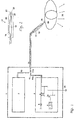
- the system according to the present invention comprises an HF generator 3, which generates an HF voltage by means of a switching transistor 5, a resonance transformer 6, the HF voltage being applied through a coaxial line 11 and a capacitor 18 with a small capacitance of approx an electrode 22 is passed. This electrode 22 is accommodated in a nozzle 23 at the end of the handpiece 17.
- an easily ionizable gas such as helium is passed from a storage container 2, not described here, through a gas supply line 12 in the handpiece cable 14 of the handpiece 17 into the handpiece 17.
- the gas connection 19 is connected to a metal tube 20 within the handpiece and has the gas openings 21 and the electrode 22 (FIG. 2).
- the gas flows out of the nozzle 23 via the gas openings 21. If the HF generator 3 is switched on, the HF current flows through the coaxial line 11, the handpiece cable 14 and the capacitor 18 to the electrode 22. If the HF voltage is sufficiently high, the electrode 22 and the tissue surface 29 are exposed treating patient a discharge 28.
- the HF current flows as a capacitive displacement current 30 from the patient to the earth and from the earth connection 31 back to the HF generator.
- a neutral electrode as is required in conventional HF surgery, is not required.
- Capacitor 18 in handpiece 17 limits the HF current to the maximum values of less than 150 mA valid for HF surgery (IEC 601-2-2).
- the presence of the capacitor 18, which together with the secondary winding of the resonance transformer 6 forms a resonance circuit, and the restriction of the HF current are of great importance in connection with the present invention.
- the relatively low HF current of approx. 20 to 100 mA causes only slight heating in the discharge channel. Due to the very small point of impact of the arc on the tissue (with impact areas of a few hundred micrometers) there is a very high current density locally that heats the tissue. This current density drops very little Distance from the point of impact of the arc to values that are not significant Heat the tissue more. Since the radio frequency essentially from A patient flows as a capacitive displacement current to the mass, becomes a current flow through the tissue and thus possible damage to deeper tissue layers avoided.
- FIG. 3 shows an oscillator 4, which has a rectangular voltage across the switching transistor 5 supplies.
- This switching transistor 5 turns on and sets the of the automatically controllable voltage source 8 and power consumption / limitation 7 delivered Voltage periodically to the primary winding of the resonance transformer 6.
- This resonance transformer 6 has a primary winding with approx. 3 to 30 turns and a secondary winding with 50 to 1000 turns (preferably 100 to 500), on one Ferrite core with an air gap are applied.
- the capacitance 15 (FIG. 3) of the coaxial line 11 forms in the handpiece cable 14 together with the secondary winding of the resonance transformer 6 a resonant circuit.
- the switching transistor 5 with the resonance frequency of the resonance transformer 6 is controlled, so supplies the secondary winding of the resonance transformer 6 a high sinusoidal RF voltage of 2000 to 4000 volts.
- the HF current flows through the capacitor 18 in the handpiece 17 to the electrode 22.
- An easily ionizable Gas such as helium becomes through the gas supply line 12 in the handpiece cable 14 to the electrode tip 22 passed, which sits in a nozzle 23 or can protrude from it.
- the high RF voltage creates a plasma discharge in the form of an electrical discharge (an arc) 28 against the patient's tissue surface 29.
- the patient educates the stray capacitance 16 existing relative to the ground.
- the HF current flows through it Stray capacitance and the ground potential back to the resonance transmitter 6th position 32 ( Figure 3) shows the schematic current profile.
- the impedance of the electrical discharge (arc) depends on the length of the Arc and on the amount of RF current.
- the electrical discharge impedance (of the arc) drops sharply at high current densities in the arc. Therefore the HF current must be limited. This is done through the impedance of the handpiece capacitor 18 ( Figures 1 and 2).
- Handpiece capacitor 18 will, depending on what is desired HF current, preferably with a capacity of 10 to 50 pF.
- At a generator frequency of approx. 350 kHz results in an impedance of approx. 9 to 45 kOhm.
- currents of approx. 65 to 330 mA flow. However only currents in the range between approx. 40 and 120 mA measured, since usually the Discharge (arc) impedance 28 is quite high.
- the high resonance quality of the resonance transformer 6 requires excitation with the exact resonance frequency. From the handpiece capacitor 18 and from the electrical Discharge (the arc) determined resonance frequency affects the resonance frequency of the resonance transmitter 6. This leads to a sharp drop in the resonance frequency at the time the plasma discharge begins. This resonance drop is depending on the discharge conditions within the discharge (arc) 28 different. For this reason, precise frequency control of the oscillator is important Ratio to the actual resonance frequency of the resonance transmitter 6 necessary. A deviation of the actual resonance frequency from the oscillator frequency is as Change in the phase angle between the oscillator signal and the signal at the Primary winding of resonance transformer 6 detectable.
- the phase comparison stage 10 compares the two phase angles in relation to each other and provides the actual one Value to the automatic frequency control circuit 9 ( Figure 3). The phase angle gives way from the predetermined value and does not exactly match the resonance frequency, the control signal corrects the oscillator frequency accordingly.
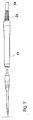
- the handpiece 17 is shown in detail in FIGS. 4 and 5.
- An easily ionizable Gas such as helium flows through a supply line 19 from the handpiece cable 14 into the metal tube 20.
- the easily ionizable gas escapes into the nozzle 23 at the gas opening 21 and leaves the handpiece 17 as a jet.
- the RF voltage supplied by the resonance transformer 6 flows through a coaxial line 11 in the handpiece cable to a metallized point 18a on an insulating layer through the dielectric 18b.
- So z. B. uses a silicone tube as a dielectric, which is pushed onto the metal tube 20.
- a thin metal foil e.g. a copper foil
- the inner conductor of the coaxial cable is in the Area 11a connected, e.g. by soldering.
- the insulating layer and the length of the metallization are so Capacities of approx. 2.5 to 150 pF can be achieved (preferably in the range between 5 and 50 pF).
- the current of the plasma discharge and thus the plasma power can be on the handpiece be adapted to requirements. Capacities of well over 50 pF will usually generate plasma currents of an intensity that is no longer surgical Applications are suitable.
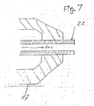
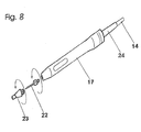
- the handpiece according to FIG. 8 has a construction similar to that in FIGS. 5, 6 and 7.
- the interchangeability of the nozzle 23 and the electrode 22 are advantages of the design according to FIG. 8.
- Figure 9 shows a handpiece with interchangeable adapters and / or tips.
- the inner one The structure is basically the same as in the embodiments according to FIGS. 5, 6, 7 and 8.
- the embodiment shown in Figure 9 has the advantage that application components different lengths and diameters can be attached.
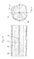
- the endoscopy tip ( Figure 10) is a possible application part for the handpiece in Figure 9.
- the tubular tip contains an inner conductor 36 Transmission of the HF current.
- This inner conductor 36 sits in a core made of insulating Plastic 35.
- PTFE is particularly suitable for this purpose.
- This core is from one Surround plastic tube 33.
- the gas only flows in axial channels (see the section through the core in Figure 10) through the plastic tube 33.
- the gas flows through the axial channels 34 in which there is a low RF field strength.
- the gas flows into an inserted one Ceramic tube 37.
- the end of the inner conductor designed as an electrode tip 22 36 lies centrally in the ceramic tube 37.
- the discharge 28 in the direction of the tissue surface 29 happens from this top.
- the cavity is advantageous because of the necessary high-frequency voltages fill the handpiece with an insulating compound 25.
- the capacity between the electrical conductor and the electrode tip must be for the Endoscopy should be as small as possible so that the RF voltage does not drop too far because the rectilinear capacitance of the conductor to the surface of the tip or to the metal parts of the endoscope forms a voltage divider with the handpiece capacitor 18.
- the Discharge current can lead to image disturbances in camera endoscopes.
- the high field strength Another problem is in the area of the conductor, since ionization already occurs here can take place. Ionization occurs especially when using helium.
- FIG. 13 shows the resonance transformer as an air coil without a core.
- the air coil has a primary winding 40 with an approximate number of turns of 18 made from one relatively thick copper wire from 1 to 1.5 mm in diameter.
- the secondary winding consists of approx. 450 turns with a wire diameter of 0.2 mm.
- An insulating film 41 separates the primary from the secondary winding.
- the primary winding is 40a, 40b 1 or 3 connected to the switching transistor 5.
- the beginning of the Secondary winding 42a is connected to ground 31, while the end 42b of the secondary winding is connected to the coaxial line of the handpiece.
- a resonance frequency of approx. 350 kHz results in a capacity of the handpiece cable of approx. 200 pF.
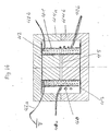
- FIG. 14 shows a resonance transformer with a ferrite core.
- the two windings 40, 42 and the coil former 43 are seated here on a two-part ferrite core 44a, 44b.
- the Air gap 45 defines the magnetic resistance and inductance of the secondary coil and thus the resonance frequency of the system at a predetermined number of Secondary coil turns.
- the advantage of this arrangement according to FIG. 14 in comparison to that in Figure 13 is the lower number of turns of the secondary winding. About 75 turns on the secondary side are sufficient here.
- the Primary winding 40 consists of three turns of enamelled copper wire of 1 mm in diameter.
- the advantages of the present HF generator for surgical cuts are the resonance transmitter and the condenser housed in the handpiece. In contrast to the conventional one HF surgery generates small peak currents.
- the construction of the present Invention eliminates the need for a neutral electrode.
- the course of the HF current corresponds to that in FIGS. 1 and 3.
- the handpiece capacitor preferably has one Capacitance from approx. 5 to 50 pF to limit the HF current.
- the oscillator is on tuned a frequency that corresponds to the resonance frequency.
- the resonance transmitter is controlled by the switching transistor.
- the handpiece according to FIG. 15 shows a construction similar to that in FIGS. 5, 6, 7 and 8.
- the interchangeability of the nozzle and the electrode is through a quick release given that is easy and safe to use.
- the quick release will guaranteed by guide contours that continue in the longitudinal direction of the handpiece 17.
- a locking mechanism can be attached to after insertion the electrode tip 22 in the handpiece 17 to define an end position.
- FIG. 16 shows additional details of an electronic circuit for generation of high frequencies for a surgical plasma device.
- the frequency is roughly through the signal (FRQ) is preselected via the processor interface 101 according to FIG. 16 Interface 101 of the processor, which provides the analog and digital signals for parameter transfer is supplied by a microprocessor (CPU bus) via appropriate software controlled (not described here in detail).
- a microprocessor CPU bus
- This signal (FRQ) reaches the voltage-controlled oscillator 102.
- the output signal (HF-OUT) is processed in position 105, i.e. the output signal (HF-OUT) is integrated and limited and then fed to a phase comparator 106.
- Phase comparator 106 now compares the phases of the output signal from the Signal generation stage 105 with the phase of the oscillator 102 - signal OSZ - derived and then gives the phase difference as an analog voltage to the frequency controller 107 further.
- the frequency control now compares the phase signal with one predefined reference value and controls the frequency of the oscillator 102 with the help of the signal (FRQ-TUNE) to a frequency whose phase difference with the previous certain reference value of the frequency matches.
- the resonance transmitter will after this process tuned to the desired resonance frequency.
- the operating voltage U reaches the power pack through a current measuring unit 108 Power stage 104.
- Current measuring unit 108 sends signal I to current limiter stage 109 and thus prevents overloading of the power amplifier 104.
- the voltage U of the power supply is reduced accordingly by the control signal DOWN as soon as the signal I-max defined current is exceeded.
- the power measurement unit 110 multiplies the actual current 1a of the output stage by that at the Power stage applied operating voltage U and delivers the result, i.e. that of Power stage 4 absorbed power, to the power controller 111.
- the power controller 111 now compares the power signal P with that from the interface provided predefined value Pmax. If this is exceeded, the The power supply voltage is reduced by the control signal DOWN until the previously set one Performance is achieved.
- the switching transistor periodically applies the primary winding of the resonance transformer to the Supply voltage. This must be exactly in sync with the resonance frequency of the resonance transmitter 6 happen.
- the resonance frequency is chosen correctly when the actual voltage an opposite potential at the primary winding at switch-on torque for operating voltage.
- the phase difference between the control signal on Switching transistor and the RF signal at the resonance transformer 6 can therefore be considered a direct Criterion for the correct resonance frequency can be used.
- Resonance transformer 6 contains a primary winding with a few turns and one Secondary winding.
- the secondary winding is with a coaxial cable from the handpiece connector connected.
- the inductance of the secondary winding and the capacity of the coaxial cable form a resonant circuit, the HF generator at its resonant frequency must be coordinated.
- the outer conductor of the coaxial cable is additional grounded.
- the amplitude of the RF voltage at the primary winding of the resonance transformer corresponds at a correct resonance frequency approximately the operating voltage.
- the automatic Control of the RF output voltage is achieved by changing the operating voltage achieved.
- Automatic control and / or limitation of the output power is achieved by directly measuring the discharge power at the resonance transformer.
- the HF generator There is one between the HF generator and the resonance transformer Monitoring circuit that the achieved power of the RF voltage and other parameters measures, tests and monitors.
- the monitoring circuit switches the device off and issues an alarm if inadmissible deviations (e.g. in the Power discharge, the HF current and other parameters) can be detected.
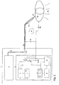
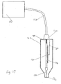
- An RF generator 121 is via a connector 123 and an RF connection cable 122 connected to a handpiece 124 with gas line.
- Handpiece 124 is connected to RF generator 121 via connecting cable 122; the RF generator 121 includes a coaxial cable and a helium gas line as well Control lines for the control button for switching on the device.
- Connection cable 122 is connected to an insulated gas pipe 130. This will be the first extended by a first condenser (position 127) which is a gas pipe owns. This first capacitor 127 is located centrally in the elongated, cylindrical one Handpiece 124.
- a capacitor 127, 128 is located in the handpiece 124, between the electrode tip and the inner conductor of the connecting cable 122. This capacitor 127, 128 limits the maximum HF current to values below a defined, predetermined Size of e.g. 150 mA, which is the maximum permissible current for HF surgery represents.
- Handpiece 124 tapers at its end and ends at connector 123; the other end carries a gas outlet opening / nozzle 125.
- the first condenser 127 extends on the outside of an electrode 126 which projects into the gas outlet opening / nozzle 125.
- a second capacitor part 128 lies opposite the first capacitor part 127.
- a connecting line 129 connects the connecting piece 123 to the second capacitor part 128.
- the electrode 126 and the gas outlet opening are located within a heat-resistant one Nozzle 125.
- the gas outlet opening and the electrode can also be used as a metal tube be formed.
- the plasma discharge (electric arc) begins this electrode.
- the capacitor can be constructed together with the electrode as one part become.
- the advantages of the system of the present invention for tissue coagulation are a very low penetration depth of the coagulation, very small RF current peaks (and thus greatly reduced current flow through the patient, since the patient is not connected to an ungrounded electrode must be connected), and clearly less damage to cells in the coagulation zone.
Landscapes
- Physics & Mathematics (AREA)
- Engineering & Computer Science (AREA)
- Health & Medical Sciences (AREA)
- Plasma & Fusion (AREA)
- Electromagnetism (AREA)
- Surgery (AREA)
- Life Sciences & Earth Sciences (AREA)
- Spectroscopy & Molecular Physics (AREA)
- Heart & Thoracic Surgery (AREA)
- Biomedical Technology (AREA)
- Otolaryngology (AREA)
- Medical Informatics (AREA)
- Molecular Biology (AREA)
- Animal Behavior & Ethology (AREA)
- General Health & Medical Sciences (AREA)
- Public Health (AREA)
- Veterinary Medicine (AREA)
- Nuclear Medicine, Radiotherapy & Molecular Imaging (AREA)
- Optics & Photonics (AREA)
- Surgical Instruments (AREA)
Applications Claiming Priority (2)
| Application Number | Priority Date | Filing Date | Title |
|---|---|---|---|
| US557906 | 1990-07-25 | ||
| US09/557,906 US6958063B1 (en) | 1999-04-22 | 2000-04-21 | Plasma generator for radio frequency surgery |
Publications (2)
| Publication Number | Publication Date |
|---|---|
| EP1148770A2 true EP1148770A2 (fr) | 2001-10-24 |
| EP1148770A3 EP1148770A3 (fr) | 2008-01-02 |
Family
ID=24227347
Family Applications (1)
| Application Number | Title | Priority Date | Filing Date |
|---|---|---|---|
| EP01104487A Withdrawn EP1148770A3 (fr) | 2000-04-21 | 2001-03-01 | Générateur de plasma pour la chirurgie HF |
Country Status (1)
| Country | Link |
|---|---|
| EP (1) | EP1148770A3 (fr) |
Cited By (12)
| Publication number | Priority date | Publication date | Assignee | Title |
|---|---|---|---|---|
| DE102008004843A1 (de) * | 2008-01-17 | 2009-09-24 | Farin, Günter, Dipl.-Ing. | Plasma-Applikatoren für plasmachirurgische Verfahren |
| DE102009017636A1 (de) * | 2009-04-16 | 2010-10-21 | Erbe Elektromedizin Gmbh | Endoskopisches Chirurgieinstrument |
| DE102009048312A1 (de) * | 2009-07-07 | 2011-01-13 | Erbe Elektromedizin Gmbh | Elektrochirurgisches Instrument und Verfahren zur Herstellung eines elektrochirurgischen Instruments |
| DE102009028190A1 (de) * | 2009-08-03 | 2011-02-10 | Leibniz-Institut für Plasmaforschung und Technologie e.V. | Vorrichtung zur Erzeugung eines nichtthermischen Atmosphärendruck-Plasmas |
| DE102009047220A1 (de) * | 2009-11-27 | 2011-06-01 | Leibniz-Institut für Plasmaforschung und Technologie e.V. | Vorrichtung und Verfahren zur Erzeugung eines gepulsten Anisothermen Atmosphärendruck-Plasmas |
| DE102012025082B3 (de) * | 2012-08-31 | 2014-01-16 | NorthCo Ventures GmbH & Co. KG | Vorrichtung und Verfahren zur Behandlung von biologischem Gewebe mit einem Niederdruckplasma |
| DE102012025079A1 (de) * | 2012-08-31 | 2014-03-06 | NorthCo Ventures GmbH & Co. KG | Vorrichtung und Verfahren zur Behandlung von biologischem Gewebe mit einem Niederdruckplasma |
| DE102012025080A1 (de) * | 2012-08-31 | 2014-03-06 | NorthCo Ventures GmbH & Co. KG | Vorrichtung und Verfahren zur Behandlung von biologischem Gewebe mit einem Niederdruckplasma |
| CN106491202A (zh) * | 2016-12-18 | 2017-03-15 | 杭州电子科技大学 | 低温等离子消融手术系统 |
| CN113141699A (zh) * | 2020-01-17 | 2021-07-20 | 飞秒科技有限公司 | 具有可更换手持件的等离子体装置 |
| CN114376546A (zh) * | 2020-12-28 | 2022-04-22 | 深圳北芯生命科技股份有限公司 | 一种支持双诊断模式的系统 |
| CN116392130A (zh) * | 2023-06-07 | 2023-07-07 | 广州思德医疗科技有限公司 | 一种食管测压装置 |
Citations (9)
| Publication number | Priority date | Publication date | Assignee | Title |
|---|---|---|---|---|
| US3903891A (en) * | 1968-01-12 | 1975-09-09 | Hogle Kearns Int | Method and apparatus for generating plasma |
| US4890073A (en) * | 1988-02-25 | 1989-12-26 | Erbe Elektromedizin Gmbh | High frequency generator for use with loads subject to great impedance variations |
| US5217457A (en) * | 1990-03-15 | 1993-06-08 | Valleylab Inc. | Enhanced electrosurgical apparatus |
| WO1997024073A1 (fr) * | 1995-12-29 | 1997-07-10 | Gyrus Medical Limited | Instrument electrochirurgical et ensemble electrode electrochirurgical |
| CA2264663A1 (fr) * | 1996-08-29 | 1998-03-05 | Bausch & Lomb Surgical, Inc. | Commande de frequence et de puissance a deux boucles |
| EP0837622A1 (fr) * | 1996-09-24 | 1998-04-22 | Jump Technologies Limited | Générateur de Plasma |
| WO1998027880A1 (fr) * | 1996-12-20 | 1998-07-02 | Gyrus Medical Limited | Generateur et systeme electrochirurgical pour fonctionnement sous l'eau |
| US5892198A (en) * | 1996-03-29 | 1999-04-06 | Lam Research Corporation | Method of and apparatus for electronically controlling r.f. energy supplied to a vacuum plasma processor and memory for same |
| US20020022836A1 (en) * | 1999-03-05 | 2002-02-21 | Gyrus Medical Limited | Electrosurgery system |
-
2001
- 2001-03-01 EP EP01104487A patent/EP1148770A3/fr not_active Withdrawn
Patent Citations (9)
| Publication number | Priority date | Publication date | Assignee | Title |
|---|---|---|---|---|
| US3903891A (en) * | 1968-01-12 | 1975-09-09 | Hogle Kearns Int | Method and apparatus for generating plasma |
| US4890073A (en) * | 1988-02-25 | 1989-12-26 | Erbe Elektromedizin Gmbh | High frequency generator for use with loads subject to great impedance variations |
| US5217457A (en) * | 1990-03-15 | 1993-06-08 | Valleylab Inc. | Enhanced electrosurgical apparatus |
| WO1997024073A1 (fr) * | 1995-12-29 | 1997-07-10 | Gyrus Medical Limited | Instrument electrochirurgical et ensemble electrode electrochirurgical |
| US5892198A (en) * | 1996-03-29 | 1999-04-06 | Lam Research Corporation | Method of and apparatus for electronically controlling r.f. energy supplied to a vacuum plasma processor and memory for same |
| CA2264663A1 (fr) * | 1996-08-29 | 1998-03-05 | Bausch & Lomb Surgical, Inc. | Commande de frequence et de puissance a deux boucles |
| EP0837622A1 (fr) * | 1996-09-24 | 1998-04-22 | Jump Technologies Limited | Générateur de Plasma |
| WO1998027880A1 (fr) * | 1996-12-20 | 1998-07-02 | Gyrus Medical Limited | Generateur et systeme electrochirurgical pour fonctionnement sous l'eau |
| US20020022836A1 (en) * | 1999-03-05 | 2002-02-21 | Gyrus Medical Limited | Electrosurgery system |
Cited By (25)
| Publication number | Priority date | Publication date | Assignee | Title |
|---|---|---|---|---|
| DE102008004843B4 (de) * | 2008-01-17 | 2012-09-20 | Günter Farin | Plasma-Applikatoren für plasmachirurgische Verfahren |
| DE102008004843A1 (de) * | 2008-01-17 | 2009-09-24 | Farin, Günter, Dipl.-Ing. | Plasma-Applikatoren für plasmachirurgische Verfahren |
| US9039703B2 (en) | 2009-04-16 | 2015-05-26 | Erbe Elektromedizin Gmbh | Endoscopic surgical instrument |
| DE102009017636A1 (de) * | 2009-04-16 | 2010-10-21 | Erbe Elektromedizin Gmbh | Endoskopisches Chirurgieinstrument |
| US9649122B2 (en) | 2009-04-16 | 2017-05-16 | Erbe Elektromedizin Gmbh | Method of manufacturing an endoscopic surgical instrument |
| DE102009048312A1 (de) * | 2009-07-07 | 2011-01-13 | Erbe Elektromedizin Gmbh | Elektrochirurgisches Instrument und Verfahren zur Herstellung eines elektrochirurgischen Instruments |
| DE102009048312B4 (de) * | 2009-07-07 | 2017-05-11 | Erbe Elektromedizin Gmbh | Elektrochirurgisches Instrument und Verfahren zur Herstellung eines elektrochirurgischen Instruments |
| US8998895B2 (en) | 2009-07-07 | 2015-04-07 | Erbe Elektromedizin Gmbh | Electrosurgical instrument and method for producing an electrosurgical instrument |
| DE102009028190A1 (de) * | 2009-08-03 | 2011-02-10 | Leibniz-Institut für Plasmaforschung und Technologie e.V. | Vorrichtung zur Erzeugung eines nichtthermischen Atmosphärendruck-Plasmas |
| DE102009047220A1 (de) * | 2009-11-27 | 2011-06-01 | Leibniz-Institut für Plasmaforschung und Technologie e.V. | Vorrichtung und Verfahren zur Erzeugung eines gepulsten Anisothermen Atmosphärendruck-Plasmas |
| WO2011063798A2 (fr) | 2009-11-27 | 2011-06-03 | Leibniz-Institut Für Plasmaforschung Und Technologie E. V. | Dispositif et procédé servant à produire un plasma pulsé anisotherme sous pression atmosphérique |
| CN104736087B (zh) * | 2012-08-31 | 2018-10-12 | 诺斯克投资有限两合公司 | 用于通过低压等离子体处理生物组织的设备和方法 |
| DE102012025082B3 (de) * | 2012-08-31 | 2014-01-16 | NorthCo Ventures GmbH & Co. KG | Vorrichtung und Verfahren zur Behandlung von biologischem Gewebe mit einem Niederdruckplasma |
| CN104736087A (zh) * | 2012-08-31 | 2015-06-24 | 诺斯克投资有限两合公司 | 用于通过低压等离子体处理生物组织的设备和方法 |
| WO2014032747A1 (fr) * | 2012-08-31 | 2014-03-06 | NorthCo Ventures GmbH & Co. KG | Dispositif et procédé de traitement d'un tissu biologique au moyen d'un plasma basse pression |
| DE102012025079B4 (de) * | 2012-08-31 | 2016-09-08 | NorthCo Ventures GmbH & Co. KG | Vorrichtung und Verfahren zur Behandlung von biologischem Gewebe mit einem Niederdruckplasma |
| DE102012025080A1 (de) * | 2012-08-31 | 2014-03-06 | NorthCo Ventures GmbH & Co. KG | Vorrichtung und Verfahren zur Behandlung von biologischem Gewebe mit einem Niederdruckplasma |
| DE102012025079A1 (de) * | 2012-08-31 | 2014-03-06 | NorthCo Ventures GmbH & Co. KG | Vorrichtung und Verfahren zur Behandlung von biologischem Gewebe mit einem Niederdruckplasma |
| CN106491202A (zh) * | 2016-12-18 | 2017-03-15 | 杭州电子科技大学 | 低温等离子消融手术系统 |
| CN106491202B (zh) * | 2016-12-18 | 2023-06-02 | 杭州电子科技大学 | 低温等离子消融手术系统 |
| CN113141699A (zh) * | 2020-01-17 | 2021-07-20 | 飞秒科技有限公司 | 具有可更换手持件的等离子体装置 |
| CN114376546A (zh) * | 2020-12-28 | 2022-04-22 | 深圳北芯生命科技股份有限公司 | 一种支持双诊断模式的系统 |
| CN114376546B (zh) * | 2020-12-28 | 2024-03-12 | 深圳北芯生命科技股份有限公司 | 一种支持双诊断模式的系统 |
| CN116392130A (zh) * | 2023-06-07 | 2023-07-07 | 广州思德医疗科技有限公司 | 一种食管测压装置 |
| CN116392130B (zh) * | 2023-06-07 | 2023-09-08 | 广州思德医疗科技有限公司 | 一种食管测压装置 |
Also Published As
| Publication number | Publication date |
|---|---|
| EP1148770A3 (fr) | 2008-01-02 |
Similar Documents
| Publication | Publication Date | Title |
|---|---|---|
| EP1109503B1 (fr) | Dispositif haute frequence permettant de produire un arc de plasma destine au traitement d'un tissu biologique | |
| DE69834501T2 (de) | Vorrichtung zum Erzeugen einer ionisierten Gasplasmaflamme zur Verwendung in der Medizin | |
| DE60121544T2 (de) | Ein elektrochirurgisches instrument und ein elektrochirurgisches system mit einem solchen instrument | |
| US6958063B1 (en) | Plasma generator for radio frequency surgery | |
| DE69628324T2 (de) | Elektrochirurgisches gerät und elektrodenvorrichtung | |
| DE60110379T2 (de) | Plasmagerät zur behandlung von gewebeoberflächen | |
| DE3851965T2 (de) | Plasma-Operationsmesser. | |
| EP0391233B1 (fr) | Appareil pour l'électro-chirurgie à haute fréquence | |
| DE3510586C2 (fr) | ||
| EP2231046B1 (fr) | Applicateurs de plasma pour procédé de chirurgie au plasma | |
| DE69636102T2 (de) | Elektrochirurgischer Generator und elektrochirurgisches System | |
| EP0521501B1 (fr) | Instrument de traitement electrochirurgical | |
| DE69715452T2 (de) | Elektrochirurghischer generator und system für verwendung unter wasser | |
| EP1858428B1 (fr) | Dispositif chirurgical haute frequence | |
| EP0430929B1 (fr) | Appareil chirurgical à haute fréquence pour la coagulation thermique de tissus biologiques | |
| DE68927424T2 (de) | Leistungssteuerung eines mit einem ionisierten Gas arbeitenden RF-Elektrochirurgiegerätes | |
| EP1148770A2 (fr) | Générateur de plasma pour la chirurgie HF | |
| WO2004110294A1 (fr) | Instrument electrochirurgical d'un endoscope ou d'un catheter | |
| DE2901153A1 (de) | Elektrochirurgischer generator | |
| EP0465422A2 (fr) | Dispositif de revêtement de surface | |
| DE10306347A1 (de) | Leistungszufuhrregeleinheit | |
| EP3141204B1 (fr) | Systeme d'ablation destine a la coagulation extensive de tissus biologiques | |
| EP3662854A1 (fr) | Dispositif de traitement de plasma | |
| DE2023140B2 (de) | Elektrochirurgisches Gerät | |
| DE102011005067A1 (de) | Hochfrequenz-Chirurgiegerät und HF-chirurgisches System |
Legal Events
| Date | Code | Title | Description |
|---|---|---|---|
| PUAI | Public reference made under article 153(3) epc to a published international application that has entered the european phase |
Free format text: ORIGINAL CODE: 0009012 |
|
| AK | Designated contracting states |
Kind code of ref document: A2 Designated state(s): AT BE CH CY DE DK ES FI FR GB GR IE IT LI LU MC NL PT SE TR |
|
| AX | Request for extension of the european patent |
Free format text: AL;LT;LV;MK;RO;SI |
|
| PUAL | Search report despatched |
Free format text: ORIGINAL CODE: 0009013 |
|
| AK | Designated contracting states |
Kind code of ref document: A3 Designated state(s): AT BE CH CY DE DK ES FI FR GB GR IE IT LI LU MC NL PT SE TR |
|
| AX | Request for extension of the european patent |
Extension state: AL LT LV MK RO SI |
|
| 17P | Request for examination filed |
Effective date: 20080304 |
|
| AKX | Designation fees paid |
Designated state(s): DE ES FR GB IT |
|
| 17Q | First examination report despatched |
Effective date: 20081118 |
|
| STAA | Information on the status of an ep patent application or granted ep patent |
Free format text: STATUS: THE APPLICATION IS DEEMED TO BE WITHDRAWN |
|
| 18D | Application deemed to be withdrawn |
Effective date: 20090331 |