EP1148526A2 - Device for degasing and brazing of premounted vacuum switch bottles - Google Patents
Device for degasing and brazing of premounted vacuum switch bottles Download PDFInfo
- Publication number
- EP1148526A2 EP1148526A2 EP01109279A EP01109279A EP1148526A2 EP 1148526 A2 EP1148526 A2 EP 1148526A2 EP 01109279 A EP01109279 A EP 01109279A EP 01109279 A EP01109279 A EP 01109279A EP 1148526 A2 EP1148526 A2 EP 1148526A2
- Authority
- EP
- European Patent Office
- Prior art keywords
- soldering
- base plate
- bell
- vacuum
- excitation coil
- Prior art date
- Legal status (The legal status is an assumption and is not a legal conclusion. Google has not performed a legal analysis and makes no representation as to the accuracy of the status listed.)
- Withdrawn
Links
Images


Classifications
-
- H—ELECTRICITY
- H01—ELECTRIC ELEMENTS
- H01H—ELECTRIC SWITCHES; RELAYS; SELECTORS; EMERGENCY PROTECTIVE DEVICES
- H01H33/00—High-tension or heavy-current switches with arc-extinguishing or arc-preventing means
- H01H33/60—Switches wherein the means for extinguishing or preventing the arc do not include separate means for obtaining or increasing flow of arc-extinguishing fluid
- H01H33/66—Vacuum switches
- H01H33/662—Housings or protective screens
- H01H33/66207—Specific housing details, e.g. sealing, soldering or brazing
Definitions
- the invention relates to a device for degassing and soldering pre-assembled vacuum interrupters in a single soldering process.
- Vacuum interrupters for vacuum circuit breakers, vacuum contactors, vacuum load disconnectors in the medium voltage range and also in the low voltage range, for example as motor protection switches, are used in many ways.
- the construction of a vacuum interrupter is shown in the drawing in FIG shown an embodiment.
- the vacuum interrupter 1 comprises the movable head 12 and the fixed head 13 connected to each other facing ends are equipped with a contact piece.
- the actual vacuum tube is formed by the metallic cover parts 15, with an insulator 14 disposed therebetween.
- the movable conductor 12 is sealed from the lid by means of the bellows 16.
- the the External parts forming the vacuum tube are connected to one another via soldering points L. connected, as well as the contact pieces 18, 19 with the conductors 12, 13. Die Contact pieces are laterally surrounded by the cylindrical screen 17, the is also firmly connected to the cover 15 via a solder joint.
- the oldest method of manufacturing the vacuum interrupter namely degassing, Welding and soldering the parts is the so-called "pinch-off process".
- the parts made of stainless steel are first made for one hour pre-degassed at approx. 1000 ° C, then the fixed contact group and the movable one Contact group pre-soldered individually, and from these parts the complete Vacuum interrupter mounted and by means of a copper tube with a Ultra high vacuum pump system coupled, and subsequently during at least 24 hours heated to a temperature of 400 ° to 500 ° C, cooled and the hydraulic tube is ultra-high vacuum tight via a hydraulic press device squeezed together - pinched off. The vacuum interrupter is then separated from the ultra high vacuum pump system.
- a complete soldering cycle takes about 10 to 12 hours, depending on the batch. It is always a discontinuous process that works with the three work stages loading furnace, soldering batch, unloading furnace, connected.
- the invention has for its object a faster and cheaper Degassing and soldering process based on the one-shot-brazing method creating vacuum interrupters, especially energy and Reduce time spent.
- a device is proposed to achieve this object, the a base plate with at least one soldering place with a Breakthrough in the base plate for connecting a suction pump and a covering the opening on the base plate and detachable bell, and a bell surrounding the outside with excitation coil with a medium or high frequency energy Medium or high frequency regenerator for the excitation coil, and one inside the bell arranged, as a cylindrical pipe section for receiving at least one pre-assembled vacuum interrupter designed susceptor having.
- the vacuum interrupters As a holder for the vacuum interrupters is preferably in the opening one on the base plate or on the base plate above the opening grid-like mounting plate for inserting the pre-assembled vacuum interrupters intended.
- the grid-like structure of the mounting plate causes a high flow conductance when pumping out the gases.
- thermocouples For precise heating to reach the soldering temperature and cooling thermocouples are provided, which in the head region of the bell by means of a high vacuum-tight implementation are arranged. Pressure measuring elements are also used for the interior and for the suction line to the suction pump, one Ultra high vacuum pump system, provided to the appropriate degassing and to achieve the corresponding high vacuum with certainty.
- the recess on the underside of the base plate is preferred Permanently connected or vacuum-tight connectable suction ports are provided.
- Rapid heating by means of the excitation coil and is essential to the invention the associated susceptor which is made of a material that is very light absorbs magnetic field lines and absorb magnetic energy very quickly can.
- the susceptor is preferably made of soft magnetic Materials such as iron and iron alloys, e.g. Fe, FeNi, FeNiCo etc. built up. This is particularly true in the lower frequency spectrum. In the higher The range of the frequency spectrum used can also be higher melting metals and alloys such as B. Mo (molybdenum), W (tungsten), Ta (tantalum), stainless steels and super alloys can be used.
- the pre-assembled vacuum interrupter opens very quickly the desired soldering temperature can be heated.
- the arrangement is preferably such that the excitation coil is ring-shaped is formed and surrounds the bell, namely transversely to the vertical switching axis the vacuum interrupter arranged inside the bell, the excitation coil being approximately centered with respect to the vacuum interrupter surrounding susceptor is arranged.
- the susceptor on insulating supports spaced from the base plate to be arranged so that he has the areas of the vacuum interrupter to be soldered surrounds outside.
- the powers that the excitation coil can deliver can be between 1.2 kW vary up to approx. 30 kW, the frequencies between 3.5 kHz and approx. 1 MHz.
- An ultra-high vacuum pump is used as the suction pump so that the pressure inside the bell can be kept below 2 x 10 -7 mbar during the entire soldering process.
- the bell can be moved, in particular, for loading and unloading the soldering device can be lifted, for example by means of a lifting device.
- the base plate with more than is preferred equipped with a soldering station, d. H. with more than one opening, whereby a bell is assigned to each opening on the top and on the Bottom of a suction nozzle. All suction ports of a base plate are over Suction lines led to a high vacuum system, and each suction nozzle is for coupling and / or disconnecting the bell with the high vacuum pump corresponding high vacuum valve assigned.
- the heater in shape the excitation coil with generator is assigned to the soldering points in such a way that corresponding movement of the excitation coil and the generator each Soldering areas can be approached one after the other with one excitation coil.
- the excitation coil with the generator in between arranged rail movable and rotatable and liftable his. If the soldering locations are arranged on a disk, it can be circular the excitation coil with the generator be arranged in the middle and through corresponding rotary movement to the individual soldering points are moved. Furthermore, the generator can be carried out with a lifting device be equipped with a vertical lifting movement.
- the manufacturing system with multiple soldering stations and a generator and an excitation coil with a control device To be provided so that the manufacturing process can be carried out automatically, d. H. loading the soldering areas, evacuating the equipped soldering areas, the heating up, cooling down and the removal and re-loading what one after the other like on a carousel.
- the controller can via PC and / or by means of a PLC control.
- each soldering place for one or more vacuum interrupters With the smallest possible space requirement are extremely short evacuation times for the soldering place below the bell possible.
- the entire device for degassing and soldering vacuum interrupters requires low investment costs due to the simple structure, but with large production quantities of vacuum interrupters in one automated or semi-automated process produced in the plant can be.
- the temperature and also the pressure in the chamber can be measured very precisely and the manufacturing process can be controlled accordingly.
- the device according to the invention is particularly suitable for manufacturing of vacuum interrupters for switch disconnectors, vacuum contactors for medium voltage and low voltage.
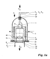
- FIG. 2 The construction of a vacuum interrupter for medium voltage and low voltage is shown by way of example in FIG. 2, as explained at the beginning.
- a vacuum interrupter for medium voltage and low voltage is shown by way of example in FIG. 2, as explained at the beginning.
- a soldering spot 2 for at least one or one small number of pre-assembled vacuum interrupters 1 is on a base plate 21 made of stainless steel.
- the soldering point 2 is on the base plate 21 an opening 27, for example in the form of a circle, is assigned.
- the top of the base plate is an annular groove around the opening 27 28 formed in which a sealing ring 22, for example a Viton O-ring, is arranged in a vacuum-tight manner connected to the base plate 21.
- a sealing ring 22 for example a Viton O-ring
- the bell 20 made of quartz glass put on.
- the suction nozzle 24 is on the underside of the base plate 21 connected to the recess 27 in a highly vacuum-tight manner, with one here Ultra high vacuum pump system, not shown, is connected.
- a high vacuum-tight bushing 23 for Thermocouples T1, T2, T3 or more to record the temperatures inside the bell jar during the manufacturing process Areas provided.
- Pre-assembled vacuum interrupter 1 is preferably on the base plate in Area of the opening 27 a receiving plate 25 preferably a lattice-shaped Mounting plate 25 or a perforated plate attached. On the mounting plate 25, a support stand 29 for the vacuum interrupter is attached.
- the pre-assembled vacuum interrupter can be held in a soldering jig with the them at the soldering point in the mounting plate or the mounting stand Insert self-centering in the switching axis X of the vacuum interrupter is supported.
- the receiving plate 25 is lattice-shaped to between the bell 20 and the suction port 24 connect with a high To allow flow conductance.
- the pressure measuring elements are P 1 and P2 built into the bell 20 or suction line 24 to the pressure during the Manufacturing process and record the necessary high vacuum over the Ensure pump system.
- the Excitation coil 3 is provided, the bell 20 in a ring transverse to the in Switch axis X vertically mounted vacuum interrupter 1 surrounds the outside.
- the excitation coil 3 is operated with medium or high frequency energy, a medium frequency generator or high frequency generator is provided for this purpose, which is not shown in detail.
- a susceptor 4 is placed inside the bell 20.
- the Susceptor 4 has the cylindrical shape of a pipe section and is on Insulating supports 40 spaced apart, arranged on the top of the base plate 21.
- the length of the susceptor 4 is such that it is the one to be soldered Areas of the vacuum interrupter 1 covered on the outside.
- the susceptor can be made of a material that is very easily magnetic field lines absorbed and thus can absorb magnetic energy very quickly, for example made of soft magnetic materials such as iron and iron alloys.
- the vacuum interrupter to be soldered can be quickly adjusted to the desired one Soldering temperature to be heated.
- the manufacturing process can proceed as follows:
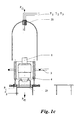
- the bell 20 is lifted in the direction of the arrow Pf1, see FIG. 1b, the preassembled vacuum interrupter 1, preassembled in a soldering jig, is inserted from its waiting place into the receiving plate 25 of the soldering place, see FIG. 1c, the bell 20 is placed on the base plate again, see Figure 1a, then the bell 20 is evacuated via the pump system connected by the suction port 24 to a value less than 2 x 10 -7 mbar.
- the vacuum interrupter 1 is then heated by applying medium-frequency energy to the excitation coil 3, the power of the coil depending on the object to be soldered being between 1.2 kW and 30 kW, the frequencies between 3.5 kHz and 1 MHz being preferred.
- the temperature inside the bell 20 and on the vacuum interrupter 1 is detected by means of the thermocouples T1, T2, T3 ... to Tn and the heating up to the soldering temperature, the soldering process and the subsequent cooling are controlled by means of a process control (not shown).
- the temperatures required for soldering the vacuum interrupter are between 700 ° C and 960 ° C.
- soldering site can be advantageous reproduce a vacuum interrupter, for example one A plurality of soldering sites on a base plate 21, such as in the Figures 3 and 4 shown schematically, are formed.
- soldering pads 2 in two parallel rows on a base plate 21 can be arranged, each soldering point having an opening 27, on the top of the base plate 21 with a susceptor 4 and one Bell 20 is equipped with thermocouples and on the underside of the Base plate 21 of the suction nozzle 24 for the connection to the high vacuum pump system is provided.
- All suction ports 24 of each soldering place 2 are with a high vacuum valve 26 for coupling and / or separating the bell 20 equipped with the high vacuum pump, the suction ports are via a further connection side 24a connected to the high vacuum pump system.
- the generator is for heating the soldering area or the vacuum interrupter 5 with the excitation coil 3 on one between the two rows of soldering sites parallel arranged rail 6 arranged in the direction of arrow Pf3.
- the generator 5 with the excitation coil 3 is on the Rail 6 is arranged to be rotatable about its vertical axis in the direction of arrow Pf4, so that the generator 5 with excitation coil 3 indiscriminately and / or in succession Approach every soldering spot in every row by moving in the direction of arrow Pf3 or Pf4.
- the manufacturing process takes place in such a way that when the bell 20 is lifted off, both the loading and unloading of the soldering area 2 is carried out with the vacuum interrupter 1 and the excitation coil 3 is moved into position or is removed from the position, and after loading and position the excitation coil, the bell 20 is placed on the soldering pad 2.
- a lifting device is also provided for positioning the excitation coil 3 in order to move the generator with the excitation coil in the direction of arrow Pf5. With the device shown in FIGS. 3 and 4, the individual soldering locations 2 can be activated one after the other and / or indiscriminately, with great flexibility in charging, soldering, decharging and cooling the vacuum interrupters to be soldered.
- the advantage is achieved that the total investment in relation to the vacuum systems and the medium-frequency or high-frequency generator can be kept small.
- the system with multiple soldering stations only requires a single ultra-high vacuum pump system in order to evacuate the individual bells 20 one after the other and / or indiscriminately. This only requires a high vacuum valve 26 between each bell and the pump system, so that each bell with its contents can be used independently.
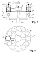
- FIGS. 5 and 6 Another possibility for increasing the production capacity is shown by the system shown schematically in FIGS. 5 and 6, in which the soldering locations 2 with glass bells 20 are arranged and formed on a disk-shaped base plate 21 in a circular ring. The system is constructed analogously to the system explained in FIGS.
- the generator 5 is arranged in the center of the base plate and can be rotated in the arrow direction Pf4 in each case by a pre-programmable angular position of the coil and, moreover, a stroke movement in the direction of the arrow Pf5 can perform.
- the heating, cooling and charging times of the soldering sites are selected so that an automatic Manufacturing process of the soldering joints can run one after the other, whereby a continuous and flexible manufacturing process is made possible.
- At least the process steps of evacuation and heating can be done via the pressure and Temperature detection of the soldering points via PC and / or PLC control be controlled and automated.
- charging is also i.e. loading and unloading with the pre-assembled vacuum interrupters included opening and closing the soldering areas by lifting and lifting the bells can be automated using robots, for example.
- the quality of the soldered and degassed vacuum interrupters can be increased and the Manufacturing costs can be reduced.
- a soldering station and a device with Soldering points for degassing and soldering vacuum interrupters in one Passage can be varied in many ways.
- a Central, oil-free forevacuum system in connection with a central high or Ultra high vacuum system can be provided as a pump system.
- each bell of a soldering station is connected to the pump system via valves.
- Decentralized ultra-high vacuum pump systems are of course also possible.
- the modular system provided according to the invention enables in a simpler manner Way to increase manufacturing capacity by adding as many Soldering places on one base plate or several base plates with several soldering places are provided, with a common ultra-high vacuum pump position is foreseeable and possibly a plurality of generators Excitation coil for the individual base plates with several soldering locations.
Abstract
Description
Die Erfindung bezieht sich auf eine Vorrichtung zum Entgasen und Verlöten von vormontierten Vakuumschaltröhren in einem einzigen Lötvorgang. Vakuumschaltröhren für Vakuumleistungsschalter, Vakuumschütze, Vakuumlasttrenner im Mittelspannungsbereich und ebenso im Niederspannungsbereich, beispielsweise als Motorschutzschalter, werden vielfältig eingesetzt.The invention relates to a device for degassing and soldering pre-assembled vacuum interrupters in a single soldering process. Vacuum interrupters for vacuum circuit breakers, vacuum contactors, vacuum load disconnectors in the medium voltage range and also in the low voltage range, for example as motor protection switches, are used in many ways.
Der Aufbau einer Vakuumschaltröhre ist in der Zeichnung in der Figur 2 an
einem Ausführungsbeispiel dargestellt. Die Vakuumschaltröhre 1 umfasst den
beweglichen Leiter 12 und den feststehenden Leiter 13, die an den einander
zugewandten stirnseitigen Enden mit einem Kontaktstück ausgestattet sind.
Die eigentliche Vakuumröhre wird von den metallischen Deckelteilen 15 gebildet,
mit einem dazwischen angeordneten Isolator 14. Der bewegliche Leiter 12
ist gegenüber dem Deckel mittels des Faltenbalges 16 abgedichtet. Die die
Vakuumröhre bildenden außenseitigen Teile sind über Lötstellen L miteinander
verbunden, ebenso die Kontaktstücke 18, 19 mit den Leitern 12, 13. Die
Kontaktstücke sind seitlich von dem zylinderförmigen Schirm 17 umgeben, der
ebenfalls über eine Lötstelle mit dem Deckel 15 fest verbunden ist.The construction of a vacuum interrupter is shown in the drawing in FIG
shown an embodiment. The
Die älteste Methode zum Fertigen der Vakuumschaltröhre, nämlich Entgasen, Schweißen und Verlöten der Teile, ist das sogenannte "Pinch-Off-Verfahren". Hierbei werden die aus Edelstahl bestehenden Teile zuerst eine Stunde lang bei ca. 1000°C vorentgast, dann wird die Festkontaktgruppe und die bewegliche Kontaktgruppe jeweils einzeln vorgelötet, und aus diesen Teilen die komplette Vakuumschaltröhre montiert und mittels eines Kupferrohres mit einer Ultrahochvakuumpumpanlage gekoppelt, und nachfolgend während mindestens 24 Stunden auf eine Temperatur von 400° bis 500°C aufgeheizt, abgekühlt und über eine hydraulische Pressvorrichtung das Kupferrohr ultrahochvakuumdicht zusammengequetscht - pinched off. Die Vakuumschaltröhre wird dann von der Ultrahochvakuumpumpanlage abgetrennt.The oldest method of manufacturing the vacuum interrupter, namely degassing, Welding and soldering the parts is the so-called "pinch-off process". The parts made of stainless steel are first made for one hour pre-degassed at approx. 1000 ° C, then the fixed contact group and the movable one Contact group pre-soldered individually, and from these parts the complete Vacuum interrupter mounted and by means of a copper tube with a Ultra high vacuum pump system coupled, and subsequently during at least 24 hours heated to a temperature of 400 ° to 500 ° C, cooled and the hydraulic tube is ultra-high vacuum tight via a hydraulic press device squeezed together - pinched off. The vacuum interrupter is then separated from the ultra high vacuum pump system.
Eine andere bekannte Methode zum Herstellen von Vakuumschaltröhren wird als Direktlotverschließtechnik bezeichnet. Hierbei werden ebenfalls die Edelstahlbauteile bei ca. 1000°C vorentgast und die Festkontaktbaugruppe und die bewegliche Kontaktbaugruppe zwischen 700°C und 960°C vorgelötet. Danach werden die gelöteten Baugruppen mit den passenden Keramikkörpern und entsprechenden Lötfolien zu der Vakuumschaltröhre vormontiert und bei Temperaturen zwischen 700° bis 860°C leergepumpt, entgast, das Getter aktiviert und die Vakuumschaltröhre ultrahochvakuumdicht verschlossen innerhalb eines Hochvakuumlötofens. Bei den vorgenannten Fertigungsmethoden handelt es sich um mehrstufige Methoden.Another known method for manufacturing vacuum interrupters is referred to as direct solder sealing technology. The stainless steel components are also used here pre-degassed at approx. 1000 ° C and the fixed contact module and the Movable contact assembly pre-soldered between 700 ° C and 960 ° C. After that the soldered assemblies with the matching ceramic bodies and appropriate solder foils to the vacuum interrupter pre-assembled and Temperatures between 700 ° and 860 ° C pumped empty, degassed, the getter activated and the vacuum interrupter sealed ultra-high vacuum inside a high vacuum soldering furnace. With the aforementioned manufacturing methods are multi-stage methods.
Darüber hinaus ist die "one-shot-brazing"-Methode bekannt, bei der alle Löt-und Entgasungsvorgänge zum Herstellen der Vakuumschaltröhre in einem einzigen Lötzyklus integriert durchgeführt werden.In addition, the "one-shot-brazing" method is known, in which all soldering and Degassing operations to manufacture the vacuum interrupter in one integrated soldering cycle.
Zum Durchführen der Direktlotverschließtechnik und des One-shot-brazing-Verfahrens
werden spezielle Hochvakuumlötöfen, die im kaltem Zustand einen
Enddruck zwischen 5 x 10⁻⁷ und 5 x 10⁻⁸ mbar erreichen können benötigt.
Diese Hochvakuumlötöfen zeichnen sich dadurch aus, dass sie aus einem
doppelwandigen Zylinder bestehen, der an beiden Enden mit einem doppelwandigen
Klöpperboden abgeschlossen ist. Einer der Klöpperboden ist als Tür
ausgeführt, damit der Ofen beladen und entladen werden kann. Der Ofen enthält
Graphit- , Molybdän- oder Wolframheizungselemente. Bei Einsatz von
Molybdän- und Wolframheizungselementen ist der Ofen mit einer metallischen
Auskleidung aus Molybdän und/oder Edelstahl versehen. Abhängig von der
Größe des Nutzraumes des Ofens und der Geometrie der herzustellenden
Vakuumschaltröhren können 50 bis 500 Vakuumschaltröhren in einer Charge
gelötet und entgast werden. Ein derartiger Lötzyklus ist aufgebaut aus:
- Ofen und Charge abkühlen lassen,
- Schnellkühlung einschalten und warten bis ca. 40 bis 70° C erreicht ist.
- Let the oven and batch cool down,
- Switch on rapid cooling and wait until approx. 40 to 70 ° C is reached.
Ein kompletter Lötzyklus dauert abhängig von der Charge ca. 10 bis 12 Stunden. Es handelt sich immer um einen diskontinuierlichen Prozess, der mit den drei Arbeitsstufen Ofen beladen, Charge löten, Ofen entladen, verbunden ist.A complete soldering cycle takes about 10 to 12 hours, depending on the batch. It is always a discontinuous process that works with the three work stages loading furnace, soldering batch, unloading furnace, connected.
Der Erfindung liegt die Aufgabe zugrunde, ein schnelleres und preiswerteres Verfahren zum Entgasen und Löten basierend auf der One-shot-brazing-Methode von Vakuumschaltröhren zu schaffen, insbesondere den Energie und Zeitaufwand zu verringern.The invention has for its object a faster and cheaper Degassing and soldering process based on the one-shot-brazing method creating vacuum interrupters, especially energy and Reduce time spent.
Erfindungsgemäß wird zur Lösung dieser Aufgabe eine Vorrichtung vorgeschlagen, die eine Grundplatte mit mindestens einem Lötplatz mit einer Durchbrechung der Grundplatte für den Anschluss einer Saugpumpe und einer die Durchbrechung überdeckenden auf die Grundplatte aufsetzbaren und abhebbaren Glocke umfasst, und eine die Glocke außenseitig umgebende mit mittel- oder hochfrequenter Energie beaufschlagbare Erregerspule mit einem Mittel- oder Hochfrequenzregenerator für die Erregerspule, und einem innerhalb der Glocke angeordneten, als zylindrisches Rohrstück für die Aufnahme mindestens einer vormontierten Vakuumschaltröhre ausgebildeten Susceptor aufweist.According to the invention, a device is proposed to achieve this object, the a base plate with at least one soldering place with a Breakthrough in the base plate for connecting a suction pump and a covering the opening on the base plate and detachable bell, and a bell surrounding the outside with excitation coil with a medium or high frequency energy Medium or high frequency regenerator for the excitation coil, and one inside the bell arranged, as a cylindrical pipe section for receiving at least one pre-assembled vacuum interrupter designed susceptor having.
Vorteilhafte Weiterbildungen und Ausgestaltungen der Erfindung sind den kennzeichnenden Merkmalen Unteransprüche entnehmbar.Advantageous further developments and refinements of the invention are the characteristic features subclaims removed.
Als Halterung für die Vakuumschaltröhren ist bevorzugt in der Durchbrechung der Grundplatte bzw. auf der Grundplatte oberhalb der Durchbrechung eine gitterartige Aufnahmeplatte zum Einsetzen der vormontierten Vakuumschaltröhren vorgesehen. Je nach Größe der Vakuumschaltröhre und des Gitters ist es möglich ggf. auch anstelle einer großen Vakuumschaltröhre mehrere kleinere Vakuumschaltröhren anzuordnen. Die gitterartige Struktur der Aufnahmeplatte bewirkt einen hohen Strömungsleitwert beim Abpumpen der Gase.As a holder for the vacuum interrupters is preferably in the opening one on the base plate or on the base plate above the opening grid-like mounting plate for inserting the pre-assembled vacuum interrupters intended. Depending on the size of the vacuum interrupter and the grid it is possible to use several smaller ones instead of one large vacuum interrupter Arrange vacuum interrupters. The grid-like structure of the mounting plate causes a high flow conductance when pumping out the gases.
Zur Erzielung eines Hochvakuums wird des weiteren vorgeschlagen, auf der Oberseite der Grundplatte eine die Durchbrechung umgebende Ringnut auszubilden, in der ein geeigneter Dichtungsring hochvakuumdicht mit der Grundplatte verbunden angeordnet ist.In order to achieve a high vacuum, it is also proposed on the To form an annular groove surrounding the opening on the top of the base plate, in which a suitable sealing ring is highly vacuum-tight with the base plate is connected connected.
Für die exakte Aufheizung zum Erreichen der Löttemperatur und Abkühlen sind Thermoelemente vorgesehen, die im Kopfbereich der Glocke mittels einer hochvakuumdichten Durchführung angeordnet sind. Ebenso sind Druckmesselemente für den Innenraum und für die Saugleitung zur Saugpumpe, einer Ultra-Hochvakuumpumpanlage, vorgesehen, um die entsprechende Entgasung und das entsprechende Hochvakuum mit Sicherheit zu erreichen.For precise heating to reach the soldering temperature and cooling thermocouples are provided, which in the head region of the bell by means of a high vacuum-tight implementation are arranged. Pressure measuring elements are also used for the interior and for the suction line to the suction pump, one Ultra high vacuum pump system, provided to the appropriate degassing and to achieve the corresponding high vacuum with certainty.
Auf der Unterseite der Grundplatte sind hierzu an der Ausnehmung bevorzugt fest angeschlossene oder vakuumdicht anschließbare Saugstutzen vorgesehen.For this purpose, the recess on the underside of the base plate is preferred Permanently connected or vacuum-tight connectable suction ports are provided.
Erfindungswesentlich ist die schnelle Aufheizung mittels der Erregerspule und dem zugeordneten Susceptor, der aus einem Material besteht, das sehr leicht magnetische Feldlinien absorbiert und sehr schnell magnetische Energie absorbieren kann. Vorzugsweise ist der Susceptor aus weichmagnetischen Werkstoffen, wie Eisen und Eisenlegierungen, z.B. Fe, FeNi, FeNiCo usw. aufgebaut. Dieses trifft besonders im unteren Frequenzspektrum zu. Im höheren Bereich des verwendeten Frequenzspektrums können auch höher schmelzende Metalle und Legierungen wie z. B. Mo (Molybdän), W (Wolfram), Ta (Tantal), Edelstähle und Superlegierungen verwendet werden. Durch Verwendung der erfindungsgemäßen mittel- oder hochfrequenten Energie kann das zu lötende Objekt , die vormontierte Vakuumschaltröhre, sehr rasch auf die gewünschte Löttemperatur erhitzt werden.Rapid heating by means of the excitation coil and is essential to the invention the associated susceptor, which is made of a material that is very light absorbs magnetic field lines and absorb magnetic energy very quickly can. The susceptor is preferably made of soft magnetic Materials such as iron and iron alloys, e.g. Fe, FeNi, FeNiCo etc. built up. This is particularly true in the lower frequency spectrum. In the higher The range of the frequency spectrum used can also be higher melting metals and alloys such as B. Mo (molybdenum), W (tungsten), Ta (tantalum), stainless steels and super alloys can be used. By using of the medium or high frequency energy according to the invention the object to be soldered, the pre-assembled vacuum interrupter, opens very quickly the desired soldering temperature can be heated.
Die Anordnung ist bevorzugt so getroffen, dass die Erregerspule ringförmig ausgebildet ist und die Glocke umgibt und zwar quer zur senkrechten Schaltachse der entsprechend innerhalb der Glocke angeordneten Vakuumschaltröhre, wobei die Erregerspule etwa mittig in bezug auf den die Vakuumschaltröhre umgebenden Susceptor angeordnet ist. Für eine optimale Erwärmung ist vorgesehen, den Susceptor auf Isolierstützen beabstandet von der Grundplatte anzuordnen, so dass er die zu lötenden Bereiche der Vakuumschaltröhre außenseitig umgibt.The arrangement is preferably such that the excitation coil is ring-shaped is formed and surrounds the bell, namely transversely to the vertical switching axis the vacuum interrupter arranged inside the bell, the excitation coil being approximately centered with respect to the vacuum interrupter surrounding susceptor is arranged. For optimal warming provided, the susceptor on insulating supports spaced from the base plate to be arranged so that he has the areas of the vacuum interrupter to be soldered surrounds outside.
Die Leistungen, die die Erregerspule abgeben kann, können zwischen 1,2 kW bis ca. 30 kW variieren, wobei die Frequenzen zwischen 3,5 kHz und ca. 1 MHz liegen.The powers that the excitation coil can deliver can be between 1.2 kW vary up to approx. 30 kW, the frequencies between 3.5 kHz and approx. 1 MHz.
Als Saugpumpe wird eine Ultra-Hochvakuumpumpe eingesetzt, so dass während des ganzen Lötvorganges der Druck innerhalb der Glocke auf einen Wert kleiner als 2 x 10⁻⁷ mbar gehalten werden kann.An ultra-high vacuum pump is used as the suction pump so that the pressure inside the bell can be kept below 2 x 10 -7 mbar during the entire soldering process.
Für das Be- und Entladen der Lötvorrichtung ist die Glocke bewegbar insbesondere hebbar, beispielsweise mittels einer Hubvorrichtung.The bell can be moved, in particular, for loading and unloading the soldering device can be lifted, for example by means of a lifting device.
Zur Steigerung der Produktivität wird bevorzugt die Grundplatte mit mehr als einem Lötplatz ausgerüstet, d. h. mit mehr als einer Durchbrechung, wobei jeder Durchbrechung eine Glocke zugeordnet ist auf der Oberseite und auf der Unterseite ein Saugstutzen. Alle Saugstutzen einer Grundplatte werden über Saugleitungen zu einer Hochvakuumanlage geführt, und jedem Saugstutzen ist zum Koppeln und/oder Trennen der Glocke mit der Hochvakuumpumpe ein entsprechendes Hochvakuumventil zugeordnet. Die Heizeinrichtung in Gestalt der Erregerspule mit Generator ist den Lötplätzen so zugeordnet, dass durch entsprechende Bewegung der Erregerspule und des Generators die einzelnen Lötplätze nacheinander mit der einen Erregerspule anfahrbar sind. Für den Fall, dass auf der Grundplatte zwei Reihen von Lötplätzen parallel zueinander vorgesehen sind, kann die Erregerspule mit dem Generator auf einer dazwischen angeordneten Schiene verfahrbar und drehbar und anhebbar angeordnet sein. Bei Anordnung der Lötplätze auf einer Scheibe kreisringförmig kann die Erregerspule mit dem Generator in der Mitte angeordnet sein und durch entsprechende Drehbewegung zu den einzelnen Lötplätzen bewegt werden. Des weiteren kann der Generator mit einer Hubeinrichtung zum Ausführen einer senkrechten Hubbewegung ausgerüstet sein.To increase productivity, the base plate with more than is preferred equipped with a soldering station, d. H. with more than one opening, whereby a bell is assigned to each opening on the top and on the Bottom of a suction nozzle. All suction ports of a base plate are over Suction lines led to a high vacuum system, and each suction nozzle is for coupling and / or disconnecting the bell with the high vacuum pump corresponding high vacuum valve assigned. The heater in shape the excitation coil with generator is assigned to the soldering points in such a way that corresponding movement of the excitation coil and the generator each Soldering areas can be approached one after the other with one excitation coil. For the Case that on the base plate two rows of soldering places parallel to each other are provided, the excitation coil with the generator in between arranged rail movable and rotatable and liftable his. If the soldering locations are arranged on a disk, it can be circular the excitation coil with the generator be arranged in the middle and through corresponding rotary movement to the individual soldering points are moved. Furthermore, the generator can be carried out with a lifting device be equipped with a vertical lifting movement.
Darüber hinaus ist es möglich, die Fertigungsanlage mit mehreren Lötplätzen und einem Generator und einer Erregerspule mit einer Steuerungseinrichtung zu versehen, so dass der Fertigungsprozess automatisch durchführbar ist, d. h. das Beschicken der Lötplätze, das Evakuieren der bestückten Lötplätze, das Aufheizen, Abkühlen und die Entnahme und das erneute Bestücken, was nacheinander wie auf einem Karussell abfolgen kann. Die Steuerung kann über PC und/oder mittels einer SPS-Steuerung erfolgen.In addition, it is possible to have the manufacturing system with multiple soldering stations and a generator and an excitation coil with a control device To be provided so that the manufacturing process can be carried out automatically, d. H. loading the soldering areas, evacuating the equipped soldering areas, the heating up, cooling down and the removal and re-loading what one after the other like on a carousel. The controller can via PC and / or by means of a PLC control.
Die erfindungsgemäße Vorrichtung ermöglicht die wirtschaftliche Herstellung von Vakuumschaltröhren. Hierbei werden folgende Vorteile erreicht:
- sehr rasche Aufwärmung der Vakuumschaltröhren durch Einsatz kleiner Einheiten, d.h. kleiner Glocken als Vakuumkammern,
- gute Kontrollmöglichkeiten der vormontierten Vakuumschaltröhre während des ganzen Lötprozesses durch Einsatz von durchsichtigen Quarzglasglocken, jede Vakuumschaltröhre ist auch visuell beobachtbar.
- Das Fließen des Lotes während des Lötprozesses der Vakuumschaltröhre ist gut zu beobachten.
- very rapid heating of the vacuum interrupters by using small units, ie small bells as vacuum chambers,
- Good control options for the pre-assembled vacuum interrupter during the entire soldering process by using transparent quartz glass bells, each vacuum interrupter can also be observed visually.
- The flow of the solder during the soldering process of the vacuum interrupter can be observed well.
Durch Ausbildung jedes Lötplatzes für eine oder mehrere Vakuumschaltröhren mit geringstmöglichem Raumbedarf sind extrem kurze Evakuierungszeiten für den Lötplatz unterhalb der Glocke möglich.By designing each soldering place for one or more vacuum interrupters with the smallest possible space requirement are extremely short evacuation times for the soldering place below the bell possible.
Durch das geringe Volumen und die Masse der Lötvorrichtung und der nur geringen Anzahl von zu lötenden Vakuumschaltröhren an einem Lötplatz können sehr niedrige Drücke während des Lötprozesses erreicht werden.Due to the small volume and mass of the soldering device and the only small number of vacuum interrupters to be soldered at a soldering station very low pressures can be achieved during the soldering process.
Die gesamte Vorrichtung zum Entgasen und Löten von Vakuumschaltröhren erfordert aufgrund des einfachen Aufbaus insgesamt geringe Investitionskosten, wobei jedoch große Fertigungsmengen an Vakuumschaltröhren in einem automatisierten oder halbautomatisierten Prozess in der Anlage hergestellt werden können.The entire device for degassing and soldering vacuum interrupters requires low investment costs due to the simple structure, but with large production quantities of vacuum interrupters in one automated or semi-automated process produced in the plant can be.
Sehr schnelle Aufheiz- und Abkühlzeiten des Lötplatzes in der Glocke sind möglich, da nur eine oder eine sehr geringe Anzahl von Vakuumschaltröhren an einem Lötplatz aufgeheizt und abgekühlt werden müssen.Very fast heating and cooling times of the soldering area in the bell are possible because only one or a very small number of vacuum interrupters must be heated and cooled at a soldering point.
Die Temperatur und auch der Druck in der Kammer kann sehr genau gemessen und der Fertigungsprozess entsprechend gesteuert werden.The temperature and also the pressure in the chamber can be measured very precisely and the manufacturing process can be controlled accordingly.
Die erfindungsgemäße Vorrichtung eignet sich insbesondere zum Herstellen von Vakuumschaltröhren für Lasttrennschalter, Vakuumschütze für Mittelspannung und Niederspannung.The device according to the invention is particularly suitable for manufacturing of vacuum interrupters for switch disconnectors, vacuum contactors for medium voltage and low voltage.
Die Erfindung wird nachfolgend anhand von in der Zeichnung schematisch dargestellte Ausführungsbeispielen näher erläutert. Es zeigen:
- Figur 1a, b, c:
- eine Lötvorrichtung mit einem Lötplatz in einer Schnittansicht in geschlossenem, geöffnetem leeren und geöffnetem mit einer Vakuumschaltröhre bestückten Zustand;
- Figur 2:
- eine vormontierte Vakuumschaltröhre im Längsschnitt;
- Figur 3 u. 4:
- eine vertikale Schnittansicht und eine Draufsicht einer Vorrichtung mit in zwei parallelen angeordneten Lötplätzen;
- Figur 5 u. 6:
- im vertikalen Schnitt und Draufsicht eine Vorrichtung mit auf einem Kreisring angeordneten Lötplätzen;
- Figur 7 u. 8:
- einen vertikalen Schnitt durch einen Lötplatz für mehrere Vakuumschaltröhren, sowie die Draufsicht hierauf in schematisierter Form.
- Figure 1a, b, c:
- a soldering device with a soldering station in a sectional view in the closed, open, empty and open state equipped with a vacuum interrupter;
- Figure 2:
- a pre-assembled vacuum interrupter in longitudinal section;
- Figure 3 u. 4:
- a vertical sectional view and a plan view of a device with two parallel soldering locations;
- Figure 5 u. 6:
- in vertical section and top view of a device with soldering points arranged on a circular ring;
- Figure 7 u. 8th:
- a vertical section through a soldering station for several vacuum interrupters, as well as the top view of this in a schematic form.
Der Aufbau einer Vakuumschaltröhre für Mittelspannung und Niederspannung
ist beispielhaft in der Figur 2, wie eingangs erläutert, dargestellt. Zum gleichzeitigen
Löten und Entgasen der vormontierten Vakuumschaltröhre und Fertigstellung
derselben, ist eine Vorrichtung mit dem prinzipiellen Aufbau nach
Figuren 1a, 1b, 1c vorgesehen. Ein Lötplatz 2 für mindestens eine oder eine
geringe Anzahl von vormontierten Vakuumschaltröhren 1 ist auf einer Grundplatte
21 aus Edelstahl eingerichtet. Dem Lötplatz 2 ist auf der Grundplatte 21
eine Durchbrechung 27, beispielsweise in Kreisform, zugeordnet. Auf der
Oberseite der Grundplatte ist um die Durchbrechung 27 eine ringförmige Nut
28 ausgebildet, in der ein Dichtungsring 22, beispielsweise ein Viton-O-Ring,
hochvakuumdicht mit der Grundplatte 21 verbunden angeordnet ist. Auf der
Grundplatte 21 und dem Dichtungsring 22 ist die Glocke 20 aus Quarzglas
aufgesetzt. Auf der Unterseite der Grundplatte 21 ist der Saugstutzen 24
hochvakuumdicht an der Ausnehmung 27 angeschlossen, der mit einer hier
nicht näher dargestellten Ultrahochvakuumpumpanlage verbunden ist. Im
Kopfbereich der Glocke 20 ist eine hochvakuumdichte Durchführung 23 für
Thermoelemente T1, T2, T3 oder auch mehr zum Erfassen der Temperaturen
innerhalb der Glasglocke während des Fertigungsprozesses an verschiedenen
Bereichen vorgesehen. Für die Halterung der zu verlötenden und entgasenden,
vormontierten Vakuumschaltröhre 1 ist auf der Grundplatte bevorzugt im
Bereich der Durchbrechung 27 eine Aufnahmeplatte 25 bevorzugt eine gitterförmige
Aufnahmeplatte 25 oder eine Lochplatte angebracht. An der Aufnahmeplatte
25 ist ein Auflageständer 29 für die Vakuumschaltröhre befestigt. Die
vormontierte Vakuumschaltröhre kann in einer Lötlehre gehaltert sein, mit der
sie an dem Lötplatz in der Aufnahmeplatte bzw. dem Aufnahmeständer durch
Einstecken selbstzentrierend in der Schaltachse X der Vakuumschaltröhre
gehaltert ist. Die Aufnahmeplatte 25 ist gitterförmig ausgebildet, um zwischen
der Glocke 20 und dem Saugstutzen 24 eine Verbindung mit einem hohen
Strömungsleitwert zu ermöglichen. Die Druckmesselemente P 1 und P2 sind
in die Glocke 20 bzw. Saugleitung 24 eingebaut, um den Druck während des
Fertigungsprozesses zu erfassen und das nötige Hochvakuum über die
Pumpanlage sicherzustellen.The construction of a vacuum interrupter for medium voltage and low voltage
is shown by way of example in FIG. 2, as explained at the beginning. For simultaneous
Soldering and degassing the pre-assembled vacuum interrupter and completion
the same, is a device with the basic structure according to
Figures 1a, 1b, 1c provided. A
Zum Erreichen einer sehr schnellen und ausreichenden Löttemperatur ist die
Erregerspule 3 vorgesehen, die die Glocke 20 ringförmig quer zur in der
Schaltachse X senkrecht gelagerten Vakuumschaltröhre 1 außenseitig umgibt.
Die Erregerspule 3 wird mit mittel- oder hochfrequenter Energie betrieben,
hierzu ist ein Mittelfrequenzgenerator oder Hochfrequenzgenerator vorgesehen,
der nicht näher dargestellt ist. Um ein homogenes Aufheizen und eine
homogene Temperatur der zu verlötenden Vakuumschaltröhre 1, die sich innerhalb
des Lötplatzes 2 befindet, zu erreichen, ist zwischen der Erregerspule
3 und der Vakuumschaltröhre 1 ein Susceptor 4 innerhalb der Glocke 20 platziert.
Der Susceptor 4 hat die zylindrische Form eines Rohrstückes und ist auf
Isolierstützen 40 beabstandet, auf der Oberseite der Grundplatte 21 angeordnet.
Die Länge des Susceptors 4 ist so bemessen, dass er die zu verlötenden
Bereiche der Vakuumschaltröhre 1 außenseitig überdeckt. Der Susceptor
kann bestehen aus einem Material , das sehr leicht magnetische Feldlinien
absorbiert und somit sehr schnell magnetische Energie absorbieren kann, beispielsweise
aus weichmagnetischen Werkstoffen wie Eisen und Eisenlegierungen.
Durch Einsatz der mittel- oder hochfrequenten Energie über die Erregerspule
3 kann die zu lötende Vakuumschaltröhre sehr rasch auf die gewünschte
Löttemperatur erhitzt werden.To achieve a very fast and sufficient soldering temperature is the
Die Glocke 20 ist in Pfeilrichtung Pf1 abgehoben, siehe Figur 1b, die vormontierte
Vakuumschaltröhre 1, vormontiert in einer Lötlehre, wird von ihrem
Warteplatz in die Aufnahmeplatte 25 des Lötplatzes eingesteckt, siehe Figur
1c, die Glocke 20 wird auf die Grundplatte wieder aufgesetzt, siehe Figur 1a,
danach erfolgt das Evakuieren der Glocke 20 über die durch den Saugstutzen
24 angeschlossene Pumpanlage bis auf einen Wert kleiner als 2 x 10⁻⁷ mbar.
Danach erfolgt das Aufheizen der Vakuumschaltröhre 1 durch Beaufschlagung
der Erregerspule 3 mit mittelfrequenter Energie, wobei die Leistung der Spule
je nach zu lötendem Objekt zwischen 1,2 kW bis 30 kW liegen kann, die Frequenzen
zwischen 3,5 kHz und 1 MHz bevorzugt. Mittels der Thermoelemente
T1, T2, T3 ... bis Tn wird die Temperatur innerhalb der Glocke 20 und an der
Vakuumschaltröhre 1 erfasst und die Aufheizzeit bis zur Löttemperatur, der
Lötvorgang und das nachfolgende Abkühlen mittels einer nicht dargestellten
Prozesssteuerung gesteuert. Die erforderlichen Temperaturen zum Löten der
Vakuumschaltröhre liegen zwischen 700°C und 960°C. Nach dem Löten und
schon während des Abkühlens wird die Glocke 20 mit sehr reinem und trockenem
Stickstoff geflutet bis zum Atmosphärendruck und wieder in Pfeilrichtung
Pf1 abgehoben und die entgaste und gelötete Vakuumschaltröhre 1 entnommen
und eine neue vormontierte Vakuumschaltröhre mit Lötlehre wieder eingesetzt.The
Für den Fall, dass kleinere Vakuumschaltröhren 1 zu entgasen und zu löten
sind, ist es auch möglich an einem Lötplatz 2, wie in der Figur 7 und 8 dargestellt,
beispielsweise 3 vormontierte Vakuumschaltröhren 1 in die Aufnahmeplatte
25 einzusetzen und wie bei Figur 1 beschrieben, den Entgasungs- und
Verlötungsprozess durchzuführen.In the event that
Vorteilhaft kann jedoch die erfindungsgemäße Ausbildung eines Lötplatzes für
eine Vakuumschaltröhre vervielfältige werden, wobei beispielsweise eine
Mehrzahl von Lötplätzen auf einer Grundplatte 21, wie beispielsweise in der
Figur 3 und 4 schematisch dargestellt, ausgebildet werden. Beispielsweise
können die Lötplätze 2 in zwei zueinander parallelen Reihen auf einer Grundplatte
21 angeordnet sein, wobei jeder Lötplatz eine Durchbrechung 27 aufweist,
auf der Oberseite der Grundplatte 21 mit einem Susceptor 4 und einer
Glocke 20 mit Thermoelementen ausgerüstet ist und auf der Unterseite der
Grundplatte 21 der Saugstutzen 24 für die Verbindung zur Hochvakuumpumpanlage
vorgesehen ist. Alle Saugstutzen 24 jedes Lötplatzes 2 sind mit
einem Hochvakuumventil 26 zum Koppeln und/oder Trennen der Glocke 20
mit der Hochvakuumpumpe ausgerüstet, die Saugstutzen werden über eine
weitere Verbindungsseite 24a mit der Hochvakuumpumpanlage verbunden.
Für die Erwärmung des Lötplatzes bzw. der Vakuumschaltröhre ist der Generator
5 mit der Erregerspule 3 auf einer zwischen den beiden Reihen von Lötplätzen
parallel angeordneten Schiene 6 verfahrbar in Pfeilrichtung Pf3 angeordnet.
Des weiteren ist der Generator 5 mit der Erregerspule 3 auf der
Schiene 6 um seine vertikale Achse in Pfeilrichtung Pf4 drehbar angeordnet,
so dass der Generator 5 mit Erregerspule 3 wahllos und/oder nacheinander
jeden Lötplatz jeder Reihe anfahren kann durch Bewegung in Pfeilrichtung Pf3
bzw. Pf4.However, the formation of a soldering site according to the invention can be advantageous
reproduce a vacuum interrupter, for example one
A plurality of soldering sites on a
Der Fertigungsprozess erfolgt in der Weise, dass bei abgehobener Glocke 20
sowohl die Be- als auch Entladung des Lötplatzes 2 mit der Vakuumschaltröhre
1 vorgenommen wird als auch die Erregerspule 3 in die Position gefahren
wird oder aus der Position entfernt wird, und nach dem Beladen und in
Position bringen der Erregerspule die Glocke 20 wieder auf den Lötplatz 2
aufgesetzt wird. Für die Positionierung der Erregerspule 3 ist des weiteren
eine Hubvorrichtung vorgesehen, um den Generator mit Erregerspule in Pfeilrichtung
Pf5 zu bewegen. Mit der in der Figur 3 und 4 dargestellten Vorrichtung
können nacheinander und/oder wahllos die einzelnen Lötplätze 2 aktiviert
werden, wobei eine große Flexibilität beim Chargieren, Löten, Dechargieren
und Abkühlen der zu lötenden Vakuumschaltröhren ermöglicht ist. Durch Ausbildung
der fahrbaren und bewegbaren Erregerspule 3 wird der Vorteil erreicht,
dass die Gesamtinvestitionen in bezug auf die Vakuumanlagen und den
mittelfrequenten oder hochfrequenten Generator klein gehalten werden kann.
Darüber hinaus benötigt die Anlage mit mehren Lötplätzen nur einen einzigen
Ultrahochvakuumpumpanlage, um die einzelnen Glocken 20 jeweils nacheinander
und/oder wahllos zu evakuieren. Hierfür ist nur ein Hochvakuumventil
26 zwischen jeder Glocke und der Pumpanlage erforderlich, so dass jede Glocke
mit Inhalt autark benutzbar wird.
Eine andere Möglichkeit zur Erhöhung der Fertigungskapazität zeigt die in den
Figuren 5 und 6 schematisch dargestellte Anlage, bei der die Lötplätze 2 mit
Glasglocken 20 auf einer scheibenförmigen Grundplatte 21 im Kreisring angeordnet
und ausgebildet sind. Die Anlage ist analog zu der in den Figuren 3 und
4 erläuterten Anlage aufgebaut, wobei hier der Generator 5 in der Mitte der
Grundplatte angeordnet ist und sowohl in Pfeilrichtung Pf4 drehbar jeweils um
vorprogrammierbare Winkelstellung der Spule bewegbar ist und darüber hinaus
auch eine Hubbewegung in Pfeilrichtung Pf5 ausführen kann.The manufacturing process takes place in such a way that when the
Another possibility for increasing the production capacity is shown by the system shown schematically in FIGS. 5 and 6, in which the
Bei Ausbildung der Anlage mit mehreren Lötplätzen können die Aufheiz-, Abkühl- und Chargierzeiten der Lötplätze so gewählt werden, dass ein automatischer Fertigungsprozess der Lötplätze nacheinander ablaufen kann, wodurch ein kontinuierlicher und flexibler Fertigungsprozess ermöglicht wird. Zumindest die Prozessschritte des Evakuierens und Aufheizens können über die Druckund Temperaturerfassung der Lötplätze über PC und/oder SPS-Steuerung gesteuert und automatisiert werden. Darüber hinaus ist auch das Chargieren, d.h. das Be- und Entladen mit den vormontierten Vakuumschaltröhren einschließlich des Öffnens und Schließens der Lötplätze durch An- und Abheben der Glocken beispielsweise mittels Robotern automatisierbar. Die Qualität der verlöteten und entgasten Vakuumschaltröhren kann gesteigert werden und die Fertigungskosten gesenkt werden.If the system is designed with several soldering points, the heating, cooling and charging times of the soldering sites are selected so that an automatic Manufacturing process of the soldering joints can run one after the other, whereby a continuous and flexible manufacturing process is made possible. At least the process steps of evacuation and heating can be done via the pressure and Temperature detection of the soldering points via PC and / or PLC control be controlled and automated. In addition, charging is also i.e. loading and unloading with the pre-assembled vacuum interrupters included opening and closing the soldering areas by lifting and lifting the bells can be automated using robots, for example. The quality of the soldered and degassed vacuum interrupters can be increased and the Manufacturing costs can be reduced.
Die erfindungsgemäße Ausbildung eines Lötplatzes und einer Vorrichtung mit Lötplätzen zum Entgasen und Verlöten von Vakuumschaltröhren in einem Durchgang kann in vielfältiger Weise variiert werden. Beispielsweise kann ein zentrales, ölfreies Vorvakuumsystem in Verbindung mit einem zentralen Hochoder Ultrahochvakuumsystem als Pumpanlage vorgesehen werden. In diesem Fall wird jede Glocke eines Lötplatzes über Ventile mit der Pumpanlage verbunden. Natürlich sind auch dezentrale Ultrahochvakuumpumpanlagen möglich. Das erfindungsgemäß vorgesehene Baukastensystem ermöglicht in einfacher Weise die Fertigungskapazität zu erhöhen, indem entsprechend viele Lötplätze auf einer Grundplatte oder mehrere Grundplatten mit mehreren Lötplätzen vorgesehen sind, wobei eine gemeinsame Ultrahoch-Vakuumpumpenlage vorsehbar ist und gegebenenfalls eine Mehrzahl von Generatoren mit Erregerspule für die einzelnen Grundplatten mit mehreren Lötplätzen.The inventive design of a soldering station and a device with Soldering points for degassing and soldering vacuum interrupters in one Passage can be varied in many ways. For example, a Central, oil-free forevacuum system in connection with a central high or Ultra high vacuum system can be provided as a pump system. In this In this case, each bell of a soldering station is connected to the pump system via valves. Decentralized ultra-high vacuum pump systems are of course also possible. The modular system provided according to the invention enables in a simpler manner Way to increase manufacturing capacity by adding as many Soldering places on one base plate or several base plates with several soldering places are provided, with a common ultra-high vacuum pump position is foreseeable and possibly a plurality of generators Excitation coil for the individual base plates with several soldering locations.
Claims (19)
Applications Claiming Priority (2)
| Application Number | Priority Date | Filing Date | Title |
|---|---|---|---|
| DE10019070A DE10019070A1 (en) | 2000-04-18 | 2000-04-18 | Device for de-gassing and soldering pre-mounted vacuum switch tubes has base plate with solder point(s), opening for connecting suction pump, bell, stimulation coil, generator and susceptor |
| DE10019070 | 2000-04-18 |
Publications (2)
| Publication Number | Publication Date |
|---|---|
| EP1148526A2 true EP1148526A2 (en) | 2001-10-24 |
| EP1148526A3 EP1148526A3 (en) | 2004-01-28 |
Family
ID=7639097
Family Applications (1)
| Application Number | Title | Priority Date | Filing Date |
|---|---|---|---|
| EP01109279A Withdrawn EP1148526A3 (en) | 2000-04-18 | 2001-04-17 | Device for degasing and brazing of premounted vacuum switch bottles |
Country Status (3)
| Country | Link |
|---|---|
| US (1) | US6476366B2 (en) |
| EP (1) | EP1148526A3 (en) |
| DE (1) | DE10019070A1 (en) |
Cited By (1)
| Publication number | Priority date | Publication date | Assignee | Title |
|---|---|---|---|---|
| CN103658605A (en) * | 2013-11-26 | 2014-03-26 | 无锡日联科技有限公司 | Casting method and device for closed type glass x-ray fixed oxygen-free copper anode target |
Families Citing this family (7)
| Publication number | Priority date | Publication date | Assignee | Title |
|---|---|---|---|---|
| DE50310817D1 (en) * | 2003-12-02 | 2009-01-02 | Comet Holding Ag | MODULAR X-RAY TUBES AND METHOD FOR THEIR PRODUCTION |
| US7365289B2 (en) * | 2004-05-18 | 2008-04-29 | The United States Of America As Represented By The Department Of Health And Human Services | Production of nanostructures by curie point induction heating |
| US7789660B2 (en) * | 2005-12-07 | 2010-09-07 | Ajax Tocco Magnethermic Corporation | Furnace alignment system |
| DE102006043018A1 (en) * | 2006-09-13 | 2008-03-27 | Switchcraft Europe Gmbh | Vacuum interrupter chamber manufacturing method involves using small sized, evacuated container, where inner dimensions marginally exceed outer dimensions of vacuum chamber, and containers are connected with high capacity vacuum pumps |
| CN102089845B (en) * | 2008-07-14 | 2013-12-18 | 西门子公司 | Method and device for producing vacuum interrupters or assemblies of vacuum interrupters, and vacuum interrupter |
| CN112885626B (en) * | 2021-01-26 | 2021-11-02 | 杭州厚域科技有限公司 | Machining method of vacuum switch assembly |
| CN114951879A (en) * | 2022-06-08 | 2022-08-30 | 希诺股份有限公司 | Low-temperature efficient vacuumizing sealing equipment and sealing process for vacuum cup |
Citations (4)
| Publication number | Priority date | Publication date | Assignee | Title |
|---|---|---|---|---|
| US2697774A (en) * | 1951-09-25 | 1954-12-21 | Standard Motor Products | Brazing machine and method |
| US2876324A (en) * | 1957-11-29 | 1959-03-03 | Sylvania Electric Prod | Induction heating apparatus |
| US3045093A (en) * | 1961-01-24 | 1962-07-17 | Gen Electric | Method for constructing arc discharge devices |
| US4197957A (en) * | 1978-12-26 | 1980-04-15 | Gte Laboratories Incorporated | Vacuum tight assembly |
Family Cites Families (4)
| Publication number | Priority date | Publication date | Assignee | Title |
|---|---|---|---|---|
| US2747066A (en) * | 1949-11-17 | 1956-05-22 | Porter H Brace | Heat treating apparatus |
| US2784285A (en) * | 1954-04-29 | 1957-03-05 | Western Electric Co | Brazing apparatus |
| US3659552A (en) * | 1966-12-15 | 1972-05-02 | Western Electric Co | Vapor deposition apparatus |
| US5753876A (en) * | 1996-05-02 | 1998-05-19 | Eaton Corporation | Clad end seal for vacuum interrupter |
-
2000
- 2000-04-18 DE DE10019070A patent/DE10019070A1/en not_active Withdrawn
-
2001
- 2001-04-17 EP EP01109279A patent/EP1148526A3/en not_active Withdrawn
- 2001-04-18 US US09/839,984 patent/US6476366B2/en not_active Expired - Fee Related
Patent Citations (4)
| Publication number | Priority date | Publication date | Assignee | Title |
|---|---|---|---|---|
| US2697774A (en) * | 1951-09-25 | 1954-12-21 | Standard Motor Products | Brazing machine and method |
| US2876324A (en) * | 1957-11-29 | 1959-03-03 | Sylvania Electric Prod | Induction heating apparatus |
| US3045093A (en) * | 1961-01-24 | 1962-07-17 | Gen Electric | Method for constructing arc discharge devices |
| US4197957A (en) * | 1978-12-26 | 1980-04-15 | Gte Laboratories Incorporated | Vacuum tight assembly |
Cited By (1)
| Publication number | Priority date | Publication date | Assignee | Title |
|---|---|---|---|---|
| CN103658605A (en) * | 2013-11-26 | 2014-03-26 | 无锡日联科技有限公司 | Casting method and device for closed type glass x-ray fixed oxygen-free copper anode target |
Also Published As
| Publication number | Publication date |
|---|---|
| US6476366B2 (en) | 2002-11-05 |
| EP1148526A3 (en) | 2004-01-28 |
| US20020014472A1 (en) | 2002-02-07 |
| DE10019070A1 (en) | 2001-10-25 |
Similar Documents
| Publication | Publication Date | Title |
|---|---|---|
| EP0419940B1 (en) | Method of manufacture of a housing for a vacuum switch | |
| EP1148526A2 (en) | Device for degasing and brazing of premounted vacuum switch bottles | |
| EP1042787A1 (en) | Holding device | |
| DE3014691A1 (en) | DEVICE FOR SINTERING IN VACUUM AND ISOSTATIC HOT PRESSES | |
| DE4403552A1 (en) | Electron cyclotron resonance device | |
| EP3140850B1 (en) | Method and apparatus for plasma treatment of substrates | |
| US2553749A (en) | Sealing fixture for the manufacture of electron discharge devices | |
| EP1228668B1 (en) | A radiant heating system with a high infrared radiant heating capacity, for treatment chambers | |
| US2598286A (en) | Method of sealing glass windows to metallic cones for cathode-ray tubes | |
| EP0409047B1 (en) | Method of manufacturing a vacuum interrupter chamber | |
| US1993022A (en) | Apparatus for heat treating electrodes | |
| DE3205501A1 (en) | Vacuum furnace for dewaxing and sintering hard metals | |
| EP0484704B1 (en) | Low voltage arc discharge and variable magnetic field for heating a substrate | |
| DE2044277C3 (en) | Process for the manufacture of an evacuated housing consisting of two ceramic tubes | |
| DE2528032C2 (en) | Electron beam generators for heating, melting and evaporation purposes | |
| DE2409818A1 (en) | METHOD FOR HEAT TREATMENT OF FERROUS AND NON-FERROUS METALS | |
| DE102006043018A1 (en) | Vacuum interrupter chamber manufacturing method involves using small sized, evacuated container, where inner dimensions marginally exceed outer dimensions of vacuum chamber, and containers are connected with high capacity vacuum pumps | |
| CH641551A5 (en) | INDUCTION POT OVEN. | |
| AT204711B (en) | Furnace for melting and casting under vacuum or inert gas atmosphere | |
| AT207972B (en) | Vacuum soldering and annealing furnace | |
| DE970576C (en) | Process for the production of an electron tube for generating ultra-high frequency electrical oscillations, preferably in the decimeter or centimeter wave length range | |
| US2859571A (en) | Method of manufacturing vacuum enclosures | |
| WO2023001507A1 (en) | Production method for an electric operating means, and electric operating means | |
| DE1192323B (en) | Method for producing welds between the parts of a housing enclosing a semiconductor element in a gastight manner and arrangements for carrying out this method | |
| DE1209214B (en) | Method for manufacturing a ceramic electron tube |
Legal Events
| Date | Code | Title | Description |
|---|---|---|---|
| PUAI | Public reference made under article 153(3) epc to a published international application that has entered the european phase |
Free format text: ORIGINAL CODE: 0009012 |
|
| AK | Designated contracting states |
Kind code of ref document: A2 Designated state(s): AT BE CH CY DE DK ES FI FR GB GR IE IT LI LU MC NL PT SE TR |
|
| AX | Request for extension of the european patent |
Free format text: AL;LT;LV;MK;RO;SI |
|
| PUAL | Search report despatched |
Free format text: ORIGINAL CODE: 0009013 |
|
| AK | Designated contracting states |
Kind code of ref document: A3 Designated state(s): AT BE CH CY DE DK ES FI FR GB GR IE IT LI LU MC NL PT SE TR |
|
| AX | Request for extension of the european patent |
Extension state: AL LT LV MK RO SI |
|
| STAA | Information on the status of an ep patent application or granted ep patent |
Free format text: STATUS: THE APPLICATION HAS BEEN WITHDRAWN |
|
| 18W | Application withdrawn |
Effective date: 20040218 |