EP1148010A1 - Device for opening signatures - Google Patents
Device for opening signatures Download PDFInfo
- Publication number
- EP1148010A1 EP1148010A1 EP00830222A EP00830222A EP1148010A1 EP 1148010 A1 EP1148010 A1 EP 1148010A1 EP 00830222 A EP00830222 A EP 00830222A EP 00830222 A EP00830222 A EP 00830222A EP 1148010 A1 EP1148010 A1 EP 1148010A1
- Authority
- EP
- European Patent Office
- Prior art keywords
- opening
- signature
- signatures
- station
- lip
- Prior art date
- Legal status (The legal status is an assumption and is not a legal conclusion. Google has not performed a legal analysis and makes no representation as to the accuracy of the status listed.)
- Granted
Links
Images

Classifications
-
- B—PERFORMING OPERATIONS; TRANSPORTING
- B65—CONVEYING; PACKING; STORING; HANDLING THIN OR FILAMENTARY MATERIAL
- B65H—HANDLING THIN OR FILAMENTARY MATERIAL, e.g. SHEETS, WEBS, CABLES
- B65H5/00—Feeding articles separated from piles; Feeding articles to machines
- B65H5/30—Opening devices for folded sheets or signatures
- B65H5/305—Opening devices for folded sheets or signatures comprising rotary means for opening the folded sheets
Definitions
- the present invention relates to an opening station for signatures.
- Signatures are commonly used for producing books.
- a signature is constituted by a large printed sheet which is folded one or more times (so as to form the pages of the book).
- a last fold defines a back of the signature, and an edge opposite the back defines a lip (or front) of the signature; the back is connected to the lip by means of an upper edge (where the reading of the page starts) and a lower edge, which define a head and a foot of the signature, respectively.
- the signature has one or more lower and upper layers, according to the number and type of folds performed.
- the signatures (of which there are a predetermined number) are sewn together in the vicinity of the back by means of a suitable machine.
- the signatures are folded and piled up together so that the sewing machine requires a station which opens the signatures in the middle before sewing.
- the opening station is typically constituted by a series of suction cups which lift the various (upper and lower) layers of the signature in sequence until its middle is reached; at this point, the signature is then dropped astride a saddle which transports the signature towards a sewing station.
- the signatures are subjected to a punching operation, for example, to define easily removable corners of the pages (as in a diary).
- the punching operation creates greater adhesion between the sheets of the signature so that the signature may not open fully when it falls on the saddle. Failure of the signature to open causes jamming of the opening station and a consequent need to interrupt the operation of the entire sewing machine; this leads to a considerable reduction in the productivity of the machine.
- a known solution consists of fanning the signatures before inserting them in the sewing machine.
- the signatures are passed between two rollers which rotate at slightly different speeds so as to create relative sliding between the sheets of the signature.
- a different known solution consists of the provision of an anvil disposed between the opening suction cups and the saddle; the anvil has a length equal to that of the lips of the signatures and extends perpendicular to an axis of supply of the signatures.
- the object of the present invention is to overcome the above-mentioned drawbacks.
- the present invention provides an opening station for signatures each having a lip with a first end and a second end, the opening station comprising means for supplying the signatures in succession along a supply axis at a predetermined supply speed, first opening means for opening each signature in the middle, in the vicinity of the first end of the lip, and second opening means for opening the signatures in the middle, along the lip, the opening station including means for moving the second opening means transverse the supply axis with a velocity having a component along the supply axis substantially equal to the supply speed, the second opening means sliding along the lip of the signature from the first end to the second end.
- the present invention also proposes a sewing machine comprising the opening station and a corresponding method of opening the signatures.
- this shows a sewing machine 100 for book signatures.
- the sewing machine includes a supply hopper 105; a pile of signatures 110 is loaded into the supply hopper 105 with the back and the head of each signature 110 facing downwards and to the left, respectively.
- An extraction pincer 115 takes the signatures 110 in succession from the bottom of the pile and supplies them to a station 120 (described in detail below) which opens each signature 110 in the middle.
- the signatures 110 are deposited astride a saddle 125 (with the back in an upper position); the saddle 125 transports the signatures 110 to a double re-forming station 130 which presses the back of each signature 110.
- the signatures 110 are then transferred to a movable saddle of a sewing station 135.
- the signatures 110 of one block constituted by a predetermined number of signatures 110 (according to the size of the book), are sewn together in the vicinity of their backs by means of a continuous thread. Once a last signature 110 of the block has been sewn, the thread is cut and the block of signatures 110 is transferred to a holder 140 (in order to be supplied to further machines which complete the production of the book).
- the operation of the sewing machine 100 is controlled by an electronic logic unit programmable by means of a control panel 145.
- the opening station of the present invention may in any case also be used in other applications, for example, in a machine which opens the signatures in the middle in order to insert loose sheets, etc.
- the opening station 120 comprises an inclined plane 203 having a downwardly curved upper end; the signatures 110 slide upwards on the plane 203 along a supply axis 206 (constituted by a longitudinal axis of the sliding plane 203).
- a set of conveyor belts 209 (three belts in the example shown in the drawing) is associated with the sliding plane 203.
- Each conveyor belt 209 is stretched between a respective pulley and a respective idle wheel (not shown in the drawing); the pulleys associated with the conveyor belts 209 are mounted on a shaft 212 driven by an electric motor (not shown in the drawing).
- Each conveyor belt 209 has a series of respective pincers 215 (for example, ten pincers) which are distributed uniformly along the belt; each pincer 215 is aligned with the corresponding pincers of the other conveyor belts 209, perpendicular to the supply axis 206.
- each pincer 215 for example, ten pincers
- a battery of lower rotary opening heads 218a, 218b, 218c and 218d and a battery of upper rotary opening heads 221a, 221b, 221c and 221d are disposed beside the sliding plane 203; a vacuum suction cup is mounted on each opening head.
- Both the lower opening heads 218a-218d and the upper opening heads 221a-221d are aligned with one another parallel to the supply axis 206.
- Each lower opening head 218a-218d and each upper opening head 221a-221d rotates about an axis (parallel to the sliding plane 203 and perpendicular to the supply axis 206) which is disposed below or above the sliding plane 203, respectively.
- a spreader wedge 230 is provided between the lower opening heads 218b and 218c (a similar wedge, not shown in the drawing, is provided between the lower opening heads 218a and 218b).
- the wedge 230 which is arranged with a longitudinal axis parallel to the supply axis 206 and a base facing forwards, moves transverse the supply axis 206.
- Gripping fingers 236 are articulated in the vicinity of the upper end of the sliding plane 203 (downstream of the opening heads 218a-218d and 221a-221d); each gripping finger 236 is constituted by a thin rearwardly-bent tube which emits an air-jet.
- the opening station has a different structure, for example, a different number of conveyor belts or of opening heads, if the opening heads are arranged differently (for example, with the opening heads aligned perpendicular to the supply axis), if the suction cups are replaced by devices with an electrostatic effect, with pressure-sensitive adhesive, etc.
- the chain 245 is stretched between two sprockets 248a, 248b.
- the sprocket 248a is connected to the drive shaft 212 by means of a geared transmission system 251, whereas the sprocket 248b is idle.
- the chain 245 forms a loop which extends transverse the supply axis 206 (obliquely) in a plane inclined to the sliding plane 203; in particular, the loop is constituted by a straight front portion and a straight rear portion (parallel to one another) connected by a left-hand arcuate portion and a right-hand arcuate portion.
- the chain 245 transports two opening elements arranged in diametrally opposed positions along the chain 245; each opening element is constituted by a metal plate terminating in an end bent upwards to define a respective opening nail 254a or 254b (facing outwards relative to the loop formed by the chain 245).
- a thin tube 257 which emits an air-jet downwards, is disposed on the frame 242, in the vicinity of the right-hand connecting portion of the loop.
- the signatures 110 are taken continuously from the supply hopper and deposited on the sliding plane 203.
- the drive shaft 212 moves the belts 209 at a constant speed (anticlockwise when viewed from the right-hand side).
- a set of pincers 215 reaches the signature 110 deposited on the sliding plane 203, each pincer 215 is closed onto the back of the signature 110.
- the signature 110 is thus thrust forwards along the supply axis 206 at a predetermined speed (for example, of the order of a few m/s, corresponding to an operating rate of a few hundreds of signatures per minute).
- the opening heads 218a-218d, 221a-221d do not interfere with the signatures 110 supplied in succession onto the sliding plane 203.
- a deflector plate (not shown in the drawing) is activated and bends a left-hand end of the lip of the signature 110, defined by the connecting point between the lip and the head, slightly towards the corresponding opening head.
- the suction cup of the opening head 218a is activated and engages a free surface of a first lower layer of the signature 110. Rotation of the opening head 218a causes a left-hand end of the first lower layer to be pulled downwards, away from the remaining part of the signature 110.
- a separating finger (not shown in the drawing) is inserted between the first lower layer and the remaining part of the signature 110 (so as to keep the signature 110 open).
- the suction cup of the opening head 218a is then de-activated, releasing the first lower layer.
- the opening head 218b is kept inactive if the signature 110 comprises only one lower layer.
- the suction cup of the opening head 218b engages a second lower layer of the signature 110 and pulls it downwards so as to open the signature 110 in the middle, in the vicinity of the left-hand end of the lip.
- the wedge 230 is then moved towards the right so as to be inserted between the two halves of the signature 110.
- the drive shaft 212 moves the sprocket 248a (clockwise when viewed from above), by means of the geared transmission system; the chain 245, and hence also the opening nails 254a, 254b, consequently move in synchronism with the belts 209, at a constant speed.
- the geared system 251 has a transmission ratio such that the opening nails 254a, 254b move (along an operative portion of the loop constituted by the rear straight portion) with a velocity having a component along the supply axis 206 equal to the speed of supply of the signatures 110.
- the nail 254a (once the left-hand connecting portion of the loop has been passed) is inserted between the two halves of the signature 110 (opened out by the wedge 230).
- the nail 254a moves (along the rear straight portion of the loop) at the same speed as the signature 110, along the supply axis 206; the movement of the nail 254a relative to the signature 110 consequently has solely a translational component (towards the right), perpendicular to the supply axis 206.
- the opening nail 254a therefore slides along the lip of the signature 110 from the left-hand end to a right-hand end (defined by the point of connection between the lip and the foot).
- the tube 257 emits an air-jet which urges the upper half of the signature 110 downwards.
- the other nail 254b is brought into the vicinity of the opening head 218b so as to be ready to act on the next signature 110.
- the suction cup of the last upper opening head 221d engages a free surface of an upper layer of the signature 110 and pulls it upwards so as to keep the signature 110 open in the middle.
- the gripping fingers 236 are then pivoted rearwardly and are inserted between the two halves of the signature 110 thus opened.
- the gripping fingers 236 restrain the lower half of the signature 110 and at the same time emit an air-jet which urges the upper half of the signature 110 upwards.
- the signature 110 is dropped astride the saddle for transportation towards the sewing station (by simultaneous opening of the pincers 215 and forward pivoting of the gripping fingers 236).
- the opening station includes first opening means for opening each signature in the middle, in the vicinity of a first end of the lip, and second opening means for opening the signature in the middle, along the lip; means are also provided in the opening station of the present invention for moving the second opening means transverse the supply axis with a velocity having a component along the supply axis substantially equal to the supply speed, so that the second opening means slide along the lip of the signature from the first end to a second end.
- the opening station according to the present invention is extremely reliable since the opening nails ensure perfect opening of the signatures in each case.
- the signatures are subjected to punching operations (although its use in other situations is not excluded).
- the signatures may in fact not be opened fully by the opening heads, because of the strong adhesion between the sheets; in fact it should be noted that an angle of opening of the signatures must be kept to a limited value in order not to risk tearing the sheets in the portions weakened by the punching operation.
- the opening nails cut any point of adhesion between the two halves of the signature along the lip.
- the structure of the present invention enables a fast signature supply speed to be maintained, ensuring high productivity of the sewing machine.
- the loop structure is extremely simple, the chain 245 ensures good reliability whilst the two opening nails 254a, 254b enable a very compact structure to be achieved.
- the air-jet which urges the upper half of the signature downwards prevents any possible interference of the signature with the opening nail along a non-operative portion of the loop (distinct from the rear straight portion) and the geared transmission system 251 ensures perfect synchronism between the belts 209 and the opening nails 254a, 254b.
- the opening station of the present invention may, however, also be implemented with the chain arranged in a loop of a different shape (for example, a triangular loop with three opening nails), with a track for transporting the opening nails, with a different number of opening nails, or with the chain driven independently of the drive shaft.
- the chain is positioned differently, for example, upstream of the opening heads (if the opening heads are aligned perpendicular to the supply axis); in this situation, it is also possible to move a single opening nail alternately towards the left and towards the right along a straight track (which is rotated alternately clockwise and anticlockwise in order to position the opening nail in the vicinity of the lip of the signature).
Landscapes
- Engineering & Computer Science (AREA)
- Mechanical Engineering (AREA)
- Feeding Of Articles By Means Other Than Belts Or Rollers (AREA)
- Collation Of Sheets And Webs (AREA)
- Control And Other Processes For Unpacking Of Materials (AREA)
- Telephone Function (AREA)
Abstract
Description
- The present invention relates to an opening station for signatures.
- Signatures are commonly used for producing books. A signature is constituted by a large printed sheet which is folded one or more times (so as to form the pages of the book). A last fold defines a back of the signature, and an edge opposite the back defines a lip (or front) of the signature; the back is connected to the lip by means of an upper edge (where the reading of the page starts) and a lower edge, which define a head and a foot of the signature, respectively. The signature has one or more lower and upper layers, according to the number and type of folds performed.
- In order to form a sewn book, the signatures (of which there are a predetermined number) are sewn together in the vicinity of the back by means of a suitable machine. The signatures are folded and piled up together so that the sewing machine requires a station which opens the signatures in the middle before sewing.
- The opening station is typically constituted by a series of suction cups which lift the various (upper and lower) layers of the signature in sequence until its middle is reached; at this point, the signature is then dropped astride a saddle which transports the signature towards a sewing station.
- In some cases, the signatures (once folded) are subjected to a punching operation, for example, to define easily removable corners of the pages (as in a diary). The punching operation creates greater adhesion between the sheets of the signature so that the signature may not open fully when it falls on the saddle. Failure of the signature to open causes jamming of the opening station and a consequent need to interrupt the operation of the entire sewing machine; this leads to a considerable reduction in the productivity of the machine.
- Various solutions have been proposed to try to solve this problem. A known solution consists of fanning the signatures before inserting them in the sewing machine. Alternatively, the signatures are passed between two rollers which rotate at slightly different speeds so as to create relative sliding between the sheets of the signature.
- A disadvantage of both of the solutions described above is that they are not very reliable since they do not ensure that the signatures open in every case. Moreover, the signatures are generally piled up together when they are loaded into the sewing machine; the weight of the overlying signatures may therefore completely cancel out any result achieved previously.
- A different known solution consists of the provision of an anvil disposed between the opening suction cups and the saddle; the anvil has a length equal to that of the lips of the signatures and extends perpendicular to an axis of supply of the signatures. Once the signature has been opened (at least partially) by the suction cups, the anvil is urged towards the lip of the signature and is then immediately retracted.
- This known solution is also rather unreliable since the anvil may not be fully inserted in the signature. Moreover, it is necessary to maintain a slow speed of supply of the signatures to allow the anvil to be retracted from the signature before the signature falls onto the saddle; this leads to low productivity of the sewing machine.
- The object of the present invention is to overcome the above-mentioned drawbacks.
- To achieve this object, an opening station for signatures as set out in the first claim is proposed.
- Briefly, the present invention provides an opening station for signatures each having a lip with a first end and a second end, the opening station comprising means for supplying the signatures in succession along a supply axis at a predetermined supply speed, first opening means for opening each signature in the middle, in the vicinity of the first end of the lip, and second opening means for opening the signatures in the middle, along the lip, the opening station including means for moving the second opening means transverse the supply axis with a velocity having a component along the supply axis substantially equal to the supply speed, the second opening means sliding along the lip of the signature from the first end to the second end.
- The present invention also proposes a sewing machine comprising the opening station and a corresponding method of opening the signatures.
- Further characteristics and the advantages of the opening station for signatures according to the present invention will become clear from the following description of a preferred embodiment thereof, given by way of non-limiting example, with reference to the appended drawings, in which:
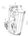
- Figure 1 is a sewing machine in which the opening station of the present invention can be used,
- Figure 2 shows the opening station in schematic form.
-
- With reference in particular to Figure 1, this shows a
sewing machine 100 for book signatures. The sewing machine includes asupply hopper 105; a pile ofsignatures 110 is loaded into thesupply hopper 105 with the back and the head of eachsignature 110 facing downwards and to the left, respectively. Anextraction pincer 115 takes thesignatures 110 in succession from the bottom of the pile and supplies them to a station 120 (described in detail below) which opens eachsignature 110 in the middle. Thesignatures 110 are deposited astride a saddle 125 (with the back in an upper position); thesaddle 125 transports thesignatures 110 to adouble re-forming station 130 which presses the back of eachsignature 110. Thesignatures 110 are then transferred to a movable saddle of asewing station 135. Thesignatures 110 of one block, constituted by a predetermined number of signatures 110 (according to the size of the book), are sewn together in the vicinity of their backs by means of a continuous thread. Once alast signature 110 of the block has been sewn, the thread is cut and the block ofsignatures 110 is transferred to a holder 140 (in order to be supplied to further machines which complete the production of the book). The operation of thesewing machine 100 is controlled by an electronic logic unit programmable by means of acontrol panel 145. - Similar considerations apply if the sewing machine has a different structure, for example, if it has a series of trays for the pre-loading of the signatures, a belt for distributing the blocks of signatures, an applicator for applying an adhesive strip around the backs of the signatures of each block, etc; the opening station of the present invention may in any case also be used in other applications, for example, in a machine which opens the signatures in the middle in order to insert loose sheets, etc.
- With reference now to Figure 2, the
opening station 120 comprises aninclined plane 203 having a downwardly curved upper end; thesignatures 110 slide upwards on theplane 203 along a supply axis 206 (constituted by a longitudinal axis of the sliding plane 203). A set of conveyor belts 209 (three belts in the example shown in the drawing) is associated with thesliding plane 203. Eachconveyor belt 209 is stretched between a respective pulley and a respective idle wheel (not shown in the drawing); the pulleys associated with theconveyor belts 209 are mounted on ashaft 212 driven by an electric motor (not shown in the drawing). Eachconveyor belt 209 has a series of respective pincers 215 (for example, ten pincers) which are distributed uniformly along the belt; eachpincer 215 is aligned with the corresponding pincers of theother conveyor belts 209, perpendicular to thesupply axis 206. - A battery of lower
rotary opening heads opening heads sliding plane 203; a vacuum suction cup is mounted on each opening head. Both the lower opening heads 218a-218d and the upperopening heads 221a-221d are aligned with one another parallel to thesupply axis 206. Each lower opening head 218a-218d and each upperopening head 221a-221d rotates about an axis (parallel to thesliding plane 203 and perpendicular to the supply axis 206) which is disposed below or above thesliding plane 203, respectively. Aspreader wedge 230 is provided between the loweropening heads 218b and 218c (a similar wedge, not shown in the drawing, is provided between the loweropening heads 218a and 218b). Thewedge 230, which is arranged with a longitudinal axis parallel to thesupply axis 206 and a base facing forwards, moves transverse thesupply axis 206. Gripping fingers 236 (two fingers in the embodiment shown in the drawing) are articulated in the vicinity of the upper end of the sliding plane 203 (downstream of the opening heads 218a-218d and 221a-221d); each grippingfinger 236 is constituted by a thin rearwardly-bent tube which emits an air-jet. - Similar considerations apply if the opening station has a different structure, for example, a different number of conveyor belts or of opening heads, if the opening heads are arranged differently (for example, with the opening heads aligned perpendicular to the supply axis), if the suction cups are replaced by devices with an electrostatic effect, with pressure-sensitive adhesive, etc.
- In the
opening station 120, in addition to the known structure described above, there is asupport frame 242 for anendless chain 245. Thechain 245 is stretched between two sprockets 248a, 248b. The sprocket 248a is connected to thedrive shaft 212 by means of a gearedtransmission system 251, whereas the sprocket 248b is idle. Thechain 245 forms a loop which extends transverse the supply axis 206 (obliquely) in a plane inclined to thesliding plane 203; in particular, the loop is constituted by a straight front portion and a straight rear portion (parallel to one another) connected by a left-hand arcuate portion and a right-hand arcuate portion. - The
chain 245 transports two opening elements arranged in diametrally opposed positions along thechain 245; each opening element is constituted by a metal plate terminating in an end bent upwards to define a respectiveopening nail 254a or 254b (facing outwards relative to the loop formed by the chain 245). Athin tube 257 which emits an air-jet downwards, is disposed on theframe 242, in the vicinity of the right-hand connecting portion of the loop. - When the sewing machine is in operation, the
signatures 110 are taken continuously from the supply hopper and deposited on thesliding plane 203. Thedrive shaft 212 moves thebelts 209 at a constant speed (anticlockwise when viewed from the right-hand side). As soon as a set ofpincers 215 reaches thesignature 110 deposited on thesliding plane 203, eachpincer 215 is closed onto the back of thesignature 110. Thesignature 110 is thus thrust forwards along thesupply axis 206 at a predetermined speed (for example, of the order of a few m/s, corresponding to an operating rate of a few hundreds of signatures per minute). - Normally, the opening heads 218a-218d, 221a-221d do not interfere with the
signatures 110 supplied in succession onto thesliding plane 203. Each time it is necessary to use an opening head, for example, the first lower opening head 218a, a deflector plate (not shown in the drawing) is activated and bends a left-hand end of the lip of thesignature 110, defined by the connecting point between the lip and the head, slightly towards the corresponding opening head. The suction cup of the opening head 218a is activated and engages a free surface of a first lower layer of thesignature 110. Rotation of the opening head 218a causes a left-hand end of the first lower layer to be pulled downwards, away from the remaining part of thesignature 110. A separating finger (not shown in the drawing) is inserted between the first lower layer and the remaining part of the signature 110 (so as to keep thesignature 110 open). The suction cup of the opening head 218a is then de-activated, releasing the first lower layer. - If the signature includes two lower layers, the same operation is repeated with the
opening head 218b (on the other hand, theopening head 218b is kept inactive if thesignature 110 comprises only one lower layer). In particular, the suction cup of theopening head 218b engages a second lower layer of thesignature 110 and pulls it downwards so as to open thesignature 110 in the middle, in the vicinity of the left-hand end of the lip. Thewedge 230 is then moved towards the right so as to be inserted between the two halves of thesignature 110. - The
drive shaft 212 moves the sprocket 248a (clockwise when viewed from above), by means of the geared transmission system; thechain 245, and hence also the openingnails 254a, 254b, consequently move in synchronism with thebelts 209, at a constant speed. The gearedsystem 251 has a transmission ratio such that the openingnails 254a, 254b move (along an operative portion of the loop constituted by the rear straight portion) with a velocity having a component along thesupply axis 206 equal to the speed of supply of thesignatures 110. - As soon as the
signature 110 passes theopening head 218b, thenail 254a (once the left-hand connecting portion of the loop has been passed) is inserted between the two halves of the signature 110 (opened out by the wedge 230). Thenail 254a moves (along the rear straight portion of the loop) at the same speed as thesignature 110, along thesupply axis 206; the movement of thenail 254a relative to thesignature 110 consequently has solely a translational component (towards the right), perpendicular to thesupply axis 206. Whilst thesignature 110 advances on the slidingplane 203, theopening nail 254a therefore slides along the lip of thesignature 110 from the left-hand end to a right-hand end (defined by the point of connection between the lip and the foot). Once thenail 254a emerges from thesignature 110, thetube 257 emits an air-jet which urges the upper half of thesignature 110 downwards. At the same time, the other nail 254b is brought into the vicinity of theopening head 218b so as to be ready to act on thenext signature 110. - The suction cup of the last upper opening head 221d engages a free surface of an upper layer of the
signature 110 and pulls it upwards so as to keep thesignature 110 open in the middle. The grippingfingers 236 are then pivoted rearwardly and are inserted between the two halves of thesignature 110 thus opened. The grippingfingers 236 restrain the lower half of thesignature 110 and at the same time emit an air-jet which urges the upper half of thesignature 110 upwards. Finally, thesignature 110 is dropped astride the saddle for transportation towards the sewing station (by simultaneous opening of thepincers 215 and forward pivoting of the gripping fingers 236). - Similar considerations apply if the signatures are supplied at a different speed, if the chain rotates in the opposite direction (with the operative portion of the loop constituted by the front straight portion), etc. More generally, the opening station includes first opening means for opening each signature in the middle, in the vicinity of a first end of the lip, and second opening means for opening the signature in the middle, along the lip; means are also provided in the opening station of the present invention for moving the second opening means transverse the supply axis with a velocity having a component along the supply axis substantially equal to the supply speed, so that the second opening means slide along the lip of the signature from the first end to a second end.
- The opening station according to the present invention is extremely reliable since the opening nails ensure perfect opening of the signatures in each case.
- This solution is particularly advantageous when the signatures are subjected to punching operations (although its use in other situations is not excluded). In this case, the signatures may in fact not be opened fully by the opening heads, because of the strong adhesion between the sheets; in fact it should be noted that an angle of opening of the signatures must be kept to a limited value in order not to risk tearing the sheets in the portions weakened by the punching operation. On the other hand, the opening nails cut any point of adhesion between the two halves of the signature along the lip.
- Moreover, the structure of the present invention enables a fast signature supply speed to be maintained, ensuring high productivity of the sewing machine.
- The particular embodiment of the opening station described above offers further advantages. For example, the loop structure is extremely simple, the
chain 245 ensures good reliability whilst the two openingnails 254a, 254b enable a very compact structure to be achieved. Moreover, the air-jet which urges the upper half of the signature downwards prevents any possible interference of the signature with the opening nail along a non-operative portion of the loop (distinct from the rear straight portion) and the gearedtransmission system 251 ensures perfect synchronism between thebelts 209 and the openingnails 254a, 254b. - The particular arrangement of the chain with the respective opening nails is perfectly adapted to the structure of pre-existing opening stations. It should be noted that this makes it impossible to use opening heads which are not disposed upstream of the chain; this limitation does not, however, generally constitute a problem and is in any case amply compensated by the advantages achieved in terms of the size of the opening station.
- Similar considerations apply if a toothed belt (or another flexible transmission element which transports the opening nails) is used, if the opening nails are replaced by similar elements, if other equivalent means are provided for urging the upper half of the signature downwards or for connecting the chain to the drive shaft, if the chain extends from a different point downstream of one of the opening heads (for example, the first), at a different point upstream of the last opening head, etc.
- The opening station of the present invention may, however, also be implemented with the chain arranged in a loop of a different shape (for example, a triangular loop with three opening nails), with a track for transporting the opening nails, with a different number of opening nails, or with the chain driven independently of the drive shaft. Alternatively, the chain is positioned differently, for example, upstream of the opening heads (if the opening heads are aligned perpendicular to the supply axis); in this situation, it is also possible to move a single opening nail alternately towards the left and towards the right along a straight track (which is rotated alternately clockwise and anticlockwise in order to position the opening nail in the vicinity of the lip of the signature).
- Naturally, in order to satisfy contingent and specific requirements, an expert in the art may apply to the above-described opening station for signatures many modifications and variations all of which, however, are included within the scope of protection of the invention, as defined by the following claims.
Claims (10)
- An opening station (120) for signatures (110) each having a lip with a first end and a second end, the opening station (120) comprising means (203, 209-215) for supplying the signatures (110) in succession along a supply axis (206) at a predetermined supply speed, first opening means (218a-218d, 221a-221d) for opening each signature (110) in the middle, in the vicinity of the first end of the lip, and second opening means (254a, 254b) for opening the signature (110) in the middle, along the lip,
characterized in that
it includes means (245, 248a, 248b) for moving the second opening means (254a, 254b) transverse the supply axis (206) at a velocity having a component along the supply axis (206) substantially equal to the supply speed, the second opening means (254a, 254b) sliding along the lip of the signature (110) from the first end to the second end. - The opening station (120) according to Claim 1, further comprising a sliding plane (203) for the signatures (110), and wherein the moving means (245, 248a, 248b) move the second opening means (254a, 254b) along a path in the form of a loop disposed in a plane inclined to the sliding plane (203), the loop comprising an operative portion and a non-operative portion for the second opening means (254a, 254b).
- The opening station (120) according to Claim 2, wherein the moving means (245, 248a, 248b) include a flexible transmission element (245) which transports the second opening means (254a, 254b) along the loop.
- The opening station (120) according to Claim 3, wherein the second opening means include a first opening element (254a) and a second opening element (254b) arranged in diametrally opposed positions along the flexible transmission element (245).
- The opening station (120) according to Claim 4, wherein each opening element includes a nail (254a, 254b) facing outwards relative to the loop.
- The opening station (120) according to any one of Claims 1 to 5, further comprising means (257) for urging a first half of the signature (110) towards a second half of the signature (110) in the vicinity of the second end of the lip.
- The opening station (120) according to any one of Claims 1 to 6, wherein the first opening means include at least one plurality of opening heads (218a-218d, 221a-221d) aligned with one another along the supply axis (206), and wherein the moving means (245, 248a, 248b) extend between a position downstream of one of the opening heads (218b, 221b) and a position upstream of a last one of the opening heads (218d, 221d).
- The opening station (120) according to any one of Claims 1 to 7, further comprising transmission means (251) for coupling the moving means (245, 248a, 248b) to the supply means (212).
- A sewing machine (100) for signatures (110) comprising the opening station (120) according to any one of Claims 1 to 8, a sewing station (135) for sewing a predetermined number of the opened signatures (110) together, and means (125) for transporting the opened signatures (110) in succession from the opening station (120) to the sewing station (135).
- A method of opening signatures (110) each having a lip with a first end and a second end, the method comprising the steps of:characterized by the step of moving the second opening means (254a, 254b) transverse the supply axis (206) with a velocity having a component along the supply axis (206) substantially equal to the supply speed, the second opening means (254a, 254b) sliding along the lip of the signature (110) from the first end to the second end.supplying the signatures (10) in succession along a supply axis (206) at a predetermined supply speed,opening each signature (110) in the middle, in the vicinity of the first end of the lip, by means of first opening means (218a-218d, 221a-221d),opening the signature (110) in the middle, along the lip, by means of second opening means (254a, 254b),
Priority Applications (3)
| Application Number | Priority Date | Filing Date | Title |
|---|---|---|---|
| AT00830222T ATE251583T1 (en) | 2000-03-23 | 2000-03-23 | DEVICE FOR OPENING SIGNATURES |
| EP00830222A EP1148010B1 (en) | 2000-03-23 | 2000-03-23 | Device for opening signatures |
| DE60005791T DE60005791T2 (en) | 2000-03-23 | 2000-03-23 | Device for opening signatures |
Applications Claiming Priority (1)
| Application Number | Priority Date | Filing Date | Title |
|---|---|---|---|
| EP00830222A EP1148010B1 (en) | 2000-03-23 | 2000-03-23 | Device for opening signatures |
Publications (2)
| Publication Number | Publication Date |
|---|---|
| EP1148010A1 true EP1148010A1 (en) | 2001-10-24 |
| EP1148010B1 EP1148010B1 (en) | 2003-10-08 |
Family
ID=8175254
Family Applications (1)
| Application Number | Title | Priority Date | Filing Date |
|---|---|---|---|
| EP00830222A Expired - Lifetime EP1148010B1 (en) | 2000-03-23 | 2000-03-23 | Device for opening signatures |
Country Status (3)
| Country | Link |
|---|---|
| EP (1) | EP1148010B1 (en) |
| AT (1) | ATE251583T1 (en) |
| DE (1) | DE60005791T2 (en) |
Citations (3)
| Publication number | Priority date | Publication date | Assignee | Title |
|---|---|---|---|---|
| US1845412A (en) * | 1923-07-16 | 1932-02-16 | Edward A Hathaway | Stuffing machine |
| DE2508194A1 (en) * | 1975-02-26 | 1976-09-09 | Guenther Dr Ing Schick | Opening unit for newspapers - has sword like flat rods mounted on guide rods to serve as openers |
| EP0596581A2 (en) * | 1990-08-27 | 1994-05-11 | Graphic Management Associates, Inc. | Opener for folded printed products |
-
2000
- 2000-03-23 EP EP00830222A patent/EP1148010B1/en not_active Expired - Lifetime
- 2000-03-23 DE DE60005791T patent/DE60005791T2/en not_active Expired - Fee Related
- 2000-03-23 AT AT00830222T patent/ATE251583T1/en not_active IP Right Cessation
Patent Citations (3)
| Publication number | Priority date | Publication date | Assignee | Title |
|---|---|---|---|---|
| US1845412A (en) * | 1923-07-16 | 1932-02-16 | Edward A Hathaway | Stuffing machine |
| DE2508194A1 (en) * | 1975-02-26 | 1976-09-09 | Guenther Dr Ing Schick | Opening unit for newspapers - has sword like flat rods mounted on guide rods to serve as openers |
| EP0596581A2 (en) * | 1990-08-27 | 1994-05-11 | Graphic Management Associates, Inc. | Opener for folded printed products |
Also Published As
| Publication number | Publication date |
|---|---|
| EP1148010B1 (en) | 2003-10-08 |
| DE60005791D1 (en) | 2003-11-13 |
| ATE251583T1 (en) | 2003-10-15 |
| DE60005791T2 (en) | 2004-05-19 |
Similar Documents
| Publication | Publication Date | Title |
|---|---|---|
| GB2225979A (en) | Method and apparatus for securing clasps to envelopes | |
| US3554531A (en) | Binder assembly | |
| JP2688085B2 (en) | METHOD AND APPARATUS FOR CARRYING OUT PRINTED MATERIALS SUPPLIED IN TILE-LIKE OVERLAP | |
| US20040256781A1 (en) | Booklet forming method and apparatus | |
| US5921538A (en) | Apparatus and method for combined gathering and binding of sheet like articles | |
| US4533132A (en) | Collating machine | |
| US5820334A (en) | Paper set feeding | |
| EP1843958B1 (en) | A method and an apparatus in the advancement of packaging blanks | |
| JP4926322B2 (en) | Rotating device for publications in conveyor lines and / or packaging machines | |
| US3806007A (en) | Textile folder | |
| EP1275523B1 (en) | Method and apparatus for inserting insert material into an envelope | |
| JP3703876B2 (en) | Printed product packaging method and equipment | |
| US4200275A (en) | Collating machine | |
| US20050062211A1 (en) | Document compiling apparatus | |
| EP1148010B1 (en) | Device for opening signatures | |
| JP2809606B2 (en) | Apparatus for quickly feeding sheet inserts to the pusher conveyor of a packaging machine | |
| GB2307469A (en) | Combining printed products | |
| US7384030B2 (en) | Method for producing a print article comprising a protective signature attached to inside folded edge of a printed product | |
| EP0344787B1 (en) | Method and device for feeding signatures on to a sewing machine | |
| EP1522419A1 (en) | Device for the automatic inserting of products into envelopes | |
| US6769676B2 (en) | Apparatus for feeding spine inserts for the mechanical manufacture of book covers | |
| RU2401240C2 (en) | Method to add one appendix to each copy of folded or stitched printed product | |
| TWI332479B (en) | ||
| US3650524A (en) | Apparatus for and method of opening interpositioned folded sheets | |
| US3672667A (en) | Apparatus for staggering blanks of sheet material |
Legal Events
| Date | Code | Title | Description |
|---|---|---|---|
| PUAI | Public reference made under article 153(3) epc to a published international application that has entered the european phase |
Free format text: ORIGINAL CODE: 0009012 |
|
| AK | Designated contracting states |
Kind code of ref document: A1 Designated state(s): AT BE CH CY DE DK ES FI FR GB GR IE IT LI LU MC NL PT SE |
|
| AX | Request for extension of the european patent |
Free format text: AL;LT;LV;MK;RO;SI |
|
| 17P | Request for examination filed |
Effective date: 20020115 |
|
| AKX | Designation fees paid |
Free format text: AT BE CH CY DE DK ES FI FR GB GR IE IT LI LU MC NL PT SE |
|
| 17Q | First examination report despatched |
Effective date: 20020930 |
|
| GRAH | Despatch of communication of intention to grant a patent |
Free format text: ORIGINAL CODE: EPIDOS IGRA |
|
| GRAS | Grant fee paid |
Free format text: ORIGINAL CODE: EPIDOSNIGR3 |
|
| GRAA | (expected) grant |
Free format text: ORIGINAL CODE: 0009210 |
|
| AK | Designated contracting states |
Kind code of ref document: B1 Designated state(s): AT BE CH CY DE DK ES FI FR GB GR IE IT LI LU MC NL PT SE |
|
| PG25 | Lapsed in a contracting state [announced via postgrant information from national office to epo] |
Ref country code: AT Free format text: LAPSE BECAUSE OF FAILURE TO SUBMIT A TRANSLATION OF THE DESCRIPTION OR TO PAY THE FEE WITHIN THE PRESCRIBED TIME-LIMIT Effective date: 20031008 Ref country code: NL Free format text: LAPSE BECAUSE OF FAILURE TO SUBMIT A TRANSLATION OF THE DESCRIPTION OR TO PAY THE FEE WITHIN THE PRESCRIBED TIME-LIMIT Effective date: 20031008 Ref country code: ES Free format text: LAPSE BECAUSE OF FAILURE TO SUBMIT A TRANSLATION OF THE DESCRIPTION OR TO PAY THE FEE WITHIN THE PRESCRIBED TIME-LIMIT Effective date: 20031008 Ref country code: BE Free format text: LAPSE BECAUSE OF FAILURE TO SUBMIT A TRANSLATION OF THE DESCRIPTION OR TO PAY THE FEE WITHIN THE PRESCRIBED TIME-LIMIT Effective date: 20031008 Ref country code: CY Free format text: LAPSE BECAUSE OF FAILURE TO SUBMIT A TRANSLATION OF THE DESCRIPTION OR TO PAY THE FEE WITHIN THE PRESCRIBED TIME-LIMIT Effective date: 20031008 Ref country code: FI Free format text: LAPSE BECAUSE OF FAILURE TO SUBMIT A TRANSLATION OF THE DESCRIPTION OR TO PAY THE FEE WITHIN THE PRESCRIBED TIME-LIMIT Effective date: 20031008 Ref country code: FR Free format text: LAPSE BECAUSE OF FAILURE TO SUBMIT A TRANSLATION OF THE DESCRIPTION OR TO PAY THE FEE WITHIN THE PRESCRIBED TIME-LIMIT Effective date: 20031008 |
|
| REG | Reference to a national code |
Ref country code: GB Ref legal event code: FG4D |
|
| REG | Reference to a national code |
Ref country code: CH Ref legal event code: EP |
|
| REG | Reference to a national code |
Ref country code: CH Ref legal event code: NV Representative=s name: JACOBACCI & PARTNERS S.P.A. |
|
| REG | Reference to a national code |
Ref country code: IE Ref legal event code: FG4D |
|
| REF | Corresponds to: |
Ref document number: 60005791 Country of ref document: DE Date of ref document: 20031113 Kind code of ref document: P |
|
| PG25 | Lapsed in a contracting state [announced via postgrant information from national office to epo] |
Ref country code: GR Free format text: LAPSE BECAUSE OF FAILURE TO SUBMIT A TRANSLATION OF THE DESCRIPTION OR TO PAY THE FEE WITHIN THE PRESCRIBED TIME-LIMIT Effective date: 20040108 Ref country code: DK Free format text: LAPSE BECAUSE OF FAILURE TO SUBMIT A TRANSLATION OF THE DESCRIPTION OR TO PAY THE FEE WITHIN THE PRESCRIBED TIME-LIMIT Effective date: 20040108 Ref country code: SE Free format text: LAPSE BECAUSE OF FAILURE TO SUBMIT A TRANSLATION OF THE DESCRIPTION OR TO PAY THE FEE WITHIN THE PRESCRIBED TIME-LIMIT Effective date: 20040108 |
|
| PGFP | Annual fee paid to national office [announced via postgrant information from national office to epo] |
Ref country code: CH Payment date: 20040213 Year of fee payment: 5 |
|
| PGFP | Annual fee paid to national office [announced via postgrant information from national office to epo] |
Ref country code: DE Payment date: 20040224 Year of fee payment: 5 |
|
| NLV1 | Nl: lapsed or annulled due to failure to fulfill the requirements of art. 29p and 29m of the patents act | ||
| PG25 | Lapsed in a contracting state [announced via postgrant information from national office to epo] |
Ref country code: LU Free format text: LAPSE BECAUSE OF NON-PAYMENT OF DUE FEES Effective date: 20040323 Ref country code: IE Free format text: LAPSE BECAUSE OF NON-PAYMENT OF DUE FEES Effective date: 20040323 Ref country code: GB Free format text: LAPSE BECAUSE OF NON-PAYMENT OF DUE FEES Effective date: 20040323 |
|
| PG25 | Lapsed in a contracting state [announced via postgrant information from national office to epo] |
Ref country code: MC Free format text: LAPSE BECAUSE OF NON-PAYMENT OF DUE FEES Effective date: 20040331 |
|
| PLBE | No opposition filed within time limit |
Free format text: ORIGINAL CODE: 0009261 |
|
| STAA | Information on the status of an ep patent application or granted ep patent |
Free format text: STATUS: NO OPPOSITION FILED WITHIN TIME LIMIT |
|
| 26N | No opposition filed |
Effective date: 20040709 |
|
| EN | Fr: translation not filed | ||
| GBPC | Gb: european patent ceased through non-payment of renewal fee |
Effective date: 20040323 |
|
| REG | Reference to a national code |
Ref country code: IE Ref legal event code: MM4A |
|
| PG25 | Lapsed in a contracting state [announced via postgrant information from national office to epo] |
Ref country code: LI Free format text: LAPSE BECAUSE OF NON-PAYMENT OF DUE FEES Effective date: 20050331 Ref country code: CH Free format text: LAPSE BECAUSE OF NON-PAYMENT OF DUE FEES Effective date: 20050331 |
|
| PG25 | Lapsed in a contracting state [announced via postgrant information from national office to epo] |
Ref country code: DE Free format text: LAPSE BECAUSE OF NON-PAYMENT OF DUE FEES Effective date: 20051001 |
|
| REG | Reference to a national code |
Ref country code: CH Ref legal event code: PL |
|
| PG25 | Lapsed in a contracting state [announced via postgrant information from national office to epo] |
Ref country code: PT Free format text: LAPSE BECAUSE OF NON-PAYMENT OF DUE FEES Effective date: 20040308 |
|
| PGFP | Annual fee paid to national office [announced via postgrant information from national office to epo] |
Ref country code: IT Payment date: 20100312 Year of fee payment: 11 |
|
| PG25 | Lapsed in a contracting state [announced via postgrant information from national office to epo] |
Ref country code: IT Free format text: LAPSE BECAUSE OF NON-PAYMENT OF DUE FEES Effective date: 20110323 |