EP1147874A2 - Moulded product ejection checking device - Google Patents
Moulded product ejection checking device Download PDFInfo
- Publication number
- EP1147874A2 EP1147874A2 EP01100597A EP01100597A EP1147874A2 EP 1147874 A2 EP1147874 A2 EP 1147874A2 EP 01100597 A EP01100597 A EP 01100597A EP 01100597 A EP01100597 A EP 01100597A EP 1147874 A2 EP1147874 A2 EP 1147874A2
- Authority
- EP
- European Patent Office
- Prior art keywords
- molded product
- waveform
- ejecting
- injection molding
- molding machine
- Prior art date
- Legal status (The legal status is an assumption and is not a legal conclusion. Google has not performed a legal analysis and makes no representation as to the accuracy of the status listed.)
- Granted
Links
Images


Classifications
-
- B—PERFORMING OPERATIONS; TRANSPORTING
- B29—WORKING OF PLASTICS; WORKING OF SUBSTANCES IN A PLASTIC STATE IN GENERAL
- B29C—SHAPING OR JOINING OF PLASTICS; SHAPING OF MATERIAL IN A PLASTIC STATE, NOT OTHERWISE PROVIDED FOR; AFTER-TREATMENT OF THE SHAPED PRODUCTS, e.g. REPAIRING
- B29C45/00—Injection moulding, i.e. forcing the required volume of moulding material through a nozzle into a closed mould; Apparatus therefor
- B29C45/17—Component parts, details or accessories; Auxiliary operations
- B29C45/40—Removing or ejecting moulded articles
-
- B—PERFORMING OPERATIONS; TRANSPORTING
- B29—WORKING OF PLASTICS; WORKING OF SUBSTANCES IN A PLASTIC STATE IN GENERAL
- B29C—SHAPING OR JOINING OF PLASTICS; SHAPING OF MATERIAL IN A PLASTIC STATE, NOT OTHERWISE PROVIDED FOR; AFTER-TREATMENT OF THE SHAPED PRODUCTS, e.g. REPAIRING
- B29C45/00—Injection moulding, i.e. forcing the required volume of moulding material through a nozzle into a closed mould; Apparatus therefor
- B29C45/17—Component parts, details or accessories; Auxiliary operations
- B29C45/76—Measuring, controlling or regulating
- B29C45/7626—Measuring, controlling or regulating the ejection or removal of moulded articles
-
- B—PERFORMING OPERATIONS; TRANSPORTING
- B29—WORKING OF PLASTICS; WORKING OF SUBSTANCES IN A PLASTIC STATE IN GENERAL
- B29C—SHAPING OR JOINING OF PLASTICS; SHAPING OF MATERIAL IN A PLASTIC STATE, NOT OTHERWISE PROVIDED FOR; AFTER-TREATMENT OF THE SHAPED PRODUCTS, e.g. REPAIRING
- B29C2945/00—Indexing scheme relating to injection moulding, i.e. forcing the required volume of moulding material through a nozzle into a closed mould
- B29C2945/76—Measuring, controlling or regulating
- B29C2945/76003—Measured parameter
- B29C2945/7602—Torque
-
- B—PERFORMING OPERATIONS; TRANSPORTING
- B29—WORKING OF PLASTICS; WORKING OF SUBSTANCES IN A PLASTIC STATE IN GENERAL
- B29C—SHAPING OR JOINING OF PLASTICS; SHAPING OF MATERIAL IN A PLASTIC STATE, NOT OTHERWISE PROVIDED FOR; AFTER-TREATMENT OF THE SHAPED PRODUCTS, e.g. REPAIRING
- B29C2945/00—Indexing scheme relating to injection moulding, i.e. forcing the required volume of moulding material through a nozzle into a closed mould
- B29C2945/76—Measuring, controlling or regulating
- B29C2945/76003—Measured parameter
- B29C2945/7611—Velocity
-
- B—PERFORMING OPERATIONS; TRANSPORTING
- B29—WORKING OF PLASTICS; WORKING OF SUBSTANCES IN A PLASTIC STATE IN GENERAL
- B29C—SHAPING OR JOINING OF PLASTICS; SHAPING OF MATERIAL IN A PLASTIC STATE, NOT OTHERWISE PROVIDED FOR; AFTER-TREATMENT OF THE SHAPED PRODUCTS, e.g. REPAIRING
- B29C2945/00—Indexing scheme relating to injection moulding, i.e. forcing the required volume of moulding material through a nozzle into a closed mould
- B29C2945/76—Measuring, controlling or regulating
- B29C2945/76003—Measured parameter
- B29C2945/76167—Presence, absence of objects
-
- B—PERFORMING OPERATIONS; TRANSPORTING
- B29—WORKING OF PLASTICS; WORKING OF SUBSTANCES IN A PLASTIC STATE IN GENERAL
- B29C—SHAPING OR JOINING OF PLASTICS; SHAPING OF MATERIAL IN A PLASTIC STATE, NOT OTHERWISE PROVIDED FOR; AFTER-TREATMENT OF THE SHAPED PRODUCTS, e.g. REPAIRING
- B29C2945/00—Indexing scheme relating to injection moulding, i.e. forcing the required volume of moulding material through a nozzle into a closed mould
- B29C2945/76—Measuring, controlling or regulating
- B29C2945/76344—Phase or stage of measurement
- B29C2945/76418—Ejection
-
- B—PERFORMING OPERATIONS; TRANSPORTING
- B29—WORKING OF PLASTICS; WORKING OF SUBSTANCES IN A PLASTIC STATE IN GENERAL
- B29C—SHAPING OR JOINING OF PLASTICS; SHAPING OF MATERIAL IN A PLASTIC STATE, NOT OTHERWISE PROVIDED FOR; AFTER-TREATMENT OF THE SHAPED PRODUCTS, e.g. REPAIRING
- B29C2945/00—Indexing scheme relating to injection moulding, i.e. forcing the required volume of moulding material through a nozzle into a closed mould
- B29C2945/76—Measuring, controlling or regulating
- B29C2945/76929—Controlling method
- B29C2945/76939—Using stored or historical data sets
- B29C2945/76943—Using stored or historical data sets compare with thresholds
-
- B—PERFORMING OPERATIONS; TRANSPORTING
- B29—WORKING OF PLASTICS; WORKING OF SUBSTANCES IN A PLASTIC STATE IN GENERAL
- B29C—SHAPING OR JOINING OF PLASTICS; SHAPING OF MATERIAL IN A PLASTIC STATE, NOT OTHERWISE PROVIDED FOR; AFTER-TREATMENT OF THE SHAPED PRODUCTS, e.g. REPAIRING
- B29C2945/00—Indexing scheme relating to injection moulding, i.e. forcing the required volume of moulding material through a nozzle into a closed mould
- B29C2945/76—Measuring, controlling or regulating
- B29C2945/76929—Controlling method
- B29C2945/76939—Using stored or historical data sets
- B29C2945/76949—Using stored or historical data sets using a learning system, i.e. the system accumulates experience from previous occurrences, e.g. adaptive control
Definitions
- the present invention relates to a device for checking that a molded product is projected (ejected) from a metal mold or a device for judging whether a molded product is normally molded or not in an injection molding machine.
- melted resin is injected into a metal mold to mold molded products.
- an ejecting device is used.
- the ejecting device has an ejecting pin driven by a motor.
- the ejecting pin is inserted into the cavity of the metal mold to project the molded product from the metal mold to drop the molded product.
- the molded product sometimes does not drop from the metal mold because of some cause (for example, the malfunction of the ejecting device). If a molding cycle is performed in this state, the metal mold may be broken or an over- packing may occur. In order to prevent such a malfunction, it is necessary to check that the molded product drops from the metal mold.
- an image processing device is conventionally used. That is, the ejecting device is operated and then the picture of the inside of the metal mold is taken from outside with the image processing device. Then, it is checked from the obtained image whether the molded product is left in the metal mold or not, and if the molded product is left in the metal mold, the next molding cycle is stopped.
- the above-mentioned checking method using the image processing device requires that the image processing device be adjusted every time the metal mold is replaced. Also, the image processing device is expensive.
- a molded product ejection checking device is combined with an ejecting device for ejecting a molded product molded in an injection molding machine.
- the ejecting device is provided with an ejecting pin driven by a motor which is controlled by a servo controller.
- a torque of the motor is obtained from a torque command from the servo controller.
- the molded product ejection checking device includes a sampling device for sampling a torque waveform of the ejecting device to obtain a detected waveform when a molded product is ejected. Also, the molded product ejection checking device includes a memory device for memorizing the torque waveform of the ejecting device when the molded product is normally ejected as a normal waveform. Further, the molded product ejection checking device includes a controlling device for judging if the molded product is normally ejected or not by the results of comparison obtained by comparing the normal wave form with the detected waveform.
- a molded product ejection checking device is used in combination with an ejecting device (not shown) mounted on an injection molding machine (not shown).
- the ejecting device has an ejecting pin driven by a motor.
- the ejecting device is also provided with a motor for driving the ejecting pin and a speed sensor for detecting the speed of the motor.
- the motor is controlled by a servo controller.
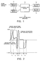
- the molded product ejection checking device includes a sampling device 11, a memory device 12, controlling device 13, and a first setting device 14, and a second setting device 15.
- the sampling device 11 samples a torque waveform based on a torque command from the servo controller at predetermined time intervals.
- a prototype of a molded product is made with an injection molding machine. Then, an ejecting condition is set where a molded product can be surely ejected, that is, dropped from a metal mold.
- the ejecting device is operated under the ejecting condition to drop the molded product from the metal mold.
- the sampling device 11 samples the torque waveform based on the torque command from the servo controller at the predetermined time intervals to obtain the sampling waveform to make the memory device 12 memorize it. That is, the torque waveform of the ejecting device at a normal operation is observed and is memorized in the memory device 12 as a normal waveform showing a reference value.
- This normal waveform will be shown by a thick solid line in Fig. 2 as the torque waveform of the ejecting device.
- a speed waveform obtained by a speed sensor of the ejecting device at a normal operation will be also shown by a thin solid line as the speed waveform of the ejecting device.
- a plurality of threshold levels are set by the first setting device 14. Also, the operation of the injection molding machine to the plurality of threshold levels is set by the second setting device 15. For example, a plurality of threshold levels to time intervals t1, t2, t3, t4, t5, t6 are set in the controlling device 13 by the first setting device 14. In the example shown in Fig. 2, a first threshold level of 120 % (absolute value) and a second threshold level of 110% (absolute value) are set at the time interval t1, as shown in Fig. 3. Also, the operation of " stop the injection molding machine " is set as an operation corresponding to the first threshold level and the operation of " output a defective product signal " is set as an operation corresponding to the second threshold level. In this connection, similarly, the threshold levels and the operations of the injection molding machine are also set at the other time intervals t2 to t6.
- the torque waveform of the ejecting device is sampled at predetermined time intervals ( ⁇ t) by the sampling device 11 and is memorized as a normal waveform into the memory device 12 (step S1).
- the threshold level is set at each time interval described above by the use of the first setting device 14.
- the operation of the injection molding machine when a comparative result (described below) is above or below the set threshold level is set by the use of the second setting device 15.
- step S3 quantity production is started by the injection molding machine.
- the sampling device 11 samples the torque waveform of the ejecting device at the predetermined time intervals to produce a detected waveform.
- the obtained detected waveform is applied to the controlling device 13.
- the controlling device 13 produces a comparative result by comparing the sampling waveform read out from the memory device 12 with the detected waveform for the time interval t1 (step S4).
- the controlling device 13 judges if the comparative result is above or below the threshold level set for the time interval t1 (step S5). If the comparative result is below the threshold level, the step of the controlling device 13 proceeds to the judgment of the comparative result for the next time interval t2. On the other hand, if the comparative result is above the threshold level, the controlling device 13 performs the operation set for the threshold level of the time interval t1 (step S6).
- controlling device 13 performs like operations as described above at time intervals t2 to t6 to check that the molded product is dropped by the ejecting device.
- the threshold levels are set at arbitrary time intervals in the above description, they may be set at sampling time intervals ( ⁇ t) of the sampling device 11. Also, the threshold level may be set in a given range instead of a single level. In this case, the controlling device 13 judges if the comparative result is in the set range or not.
- the controlling device 13 compares the detected waveform with the normal waveform. It is possible to prevent the occurrence of troubles such as a broken metal mold or the like and to judge whether a molded product passes a pass/ fail criteria or not by specifying the operation of the injection molding machine according to whether or not the comparative result exceeds the predetermined threshold level.
- the present invention judges whether the molded product is normally ejected or not by comparing the detected torque waveform of the ejecting device when the volume production is performed with the normal torque waveform when the ejecting device is normally operated, it produces an effect of checking the ejection of the molded product at low cost with reliability and also can judge whether the molded product passes a pass/ fail criteria or not.
- the invention relates to a molded product ejection checking device combined with an ejecting device for ejecting a molded product in an injection molding machine, the molded product ejection checking device comprising: a sampling device (11); and a memory device (12).
Landscapes
- Engineering & Computer Science (AREA)
- Manufacturing & Machinery (AREA)
- Mechanical Engineering (AREA)
- Injection Moulding Of Plastics Or The Like (AREA)
- Moulds For Moulding Plastics Or The Like (AREA)
- Ink Jet (AREA)
- Coating Apparatus (AREA)
- Fuel-Injection Apparatus (AREA)
- Casting Or Compression Moulding Of Plastics Or The Like (AREA)
Abstract
Description
Claims (7)
- A molded product ejection checking device combined with an ejecting device for ejecting a molded product in an injection molding machine, characterized in that the ejecting device is provided with an ejecting pin driven by a motor, a torque of the motor being obtained from a torque command from a servo controller, the molded product ejection checking device comprising:a sampling device (11) for sampling a torque waveform of the ejecting device to produce a detected waveform when the molded product is ejected;a memory device (12) for memorizing the torque waveform of the ejecting device when the molded product is normally ejected as a normal waveform; anda controlling device (13) for judging if the molded product is normally ejected or not according to the comparative result obtained by comparing the normal waveform with the detected waveform.
- A molded product ejection checking device as claimed in claim 1, characterized in that the sampling device (11) samples the torque waveform of the ejecting device at predetermined time intervals, characterized in that threshold levels are set in the controlling device (13) at arbitrary or the predetermined time intervals, and characterized in that the controlling device (13) checks whether the molded product is normally ejected or not according to whether the comparative result is above or below the threshold level.
- A molded product ejection checking device as claimed in claim 2, characterized in that an operation for specifying the operation of the injection molding machine is set in the controlling device (13) for each threshold level and characterized in that the controlling device (13) controls the injection molding machine based on the set operation.
- A molded product ejection checking device as claimed in claim 3, further comprising a setting device (14, 15) for setting the threshold levels and the set operations.
- A molded product ejection checking device as claimed in claim 4, characterized in that the normal waveform is memorized in the memory device (12) by making a prototype of a molded product before the injection molding machine starts a quantity production and characterized in that after the normal waveform is memorized in the memory device (12), the threshold levels and the set operations are set in the controlling device (13) before the quantity production is started.
- A molded product ejection checking device as claimed in any one of claims 1 to 4, characterized in that the controlling device (13) further checks whether the molded product is normally molded or not and judges whether the molded product passes a pass/ fail criteria or not according to the comparative result obtained by comparing the normal waveform with the detected waveform.
- A molded product ejection checking device combined with an ejecting device for ejecting a molded product in an injection molding machine, the molded product ejection checking device comprising:a sampling device (11); anda memory device (12).
Applications Claiming Priority (2)
| Application Number | Priority Date | Filing Date | Title |
|---|---|---|---|
| JP2000116545 | 2000-04-18 | ||
| JP2000116545A JP3455905B2 (en) | 2000-04-18 | 2000-04-18 | Mold ejection device |
Publications (3)
| Publication Number | Publication Date |
|---|---|
| EP1147874A2 true EP1147874A2 (en) | 2001-10-24 |
| EP1147874A3 EP1147874A3 (en) | 2003-04-23 |
| EP1147874B1 EP1147874B1 (en) | 2007-08-15 |
Family
ID=18627995
Family Applications (1)
| Application Number | Title | Priority Date | Filing Date |
|---|---|---|---|
| EP01100597A Expired - Lifetime EP1147874B1 (en) | 2000-04-18 | 2001-01-10 | Moulded product ejection checking device |
Country Status (9)
| Country | Link |
|---|---|
| US (1) | US6398536B2 (en) |
| EP (1) | EP1147874B1 (en) |
| JP (1) | JP3455905B2 (en) |
| KR (1) | KR100408879B1 (en) |
| CN (1) | CN1141211C (en) |
| AT (1) | ATE369967T1 (en) |
| DE (1) | DE60129875T2 (en) |
| SG (1) | SG91323A1 (en) |
| TW (1) | TW508297B (en) |
Cited By (3)
| Publication number | Priority date | Publication date | Assignee | Title |
|---|---|---|---|---|
| EP1382429A1 (en) * | 2002-07-17 | 2004-01-21 | Fanuc Ltd | Ejector unit of injection molding machine and method of detecting protrusion start position of ejector pin |
| DE10133442B4 (en) * | 2000-07-11 | 2005-05-19 | Toshiba Machine Co., Ltd. | Malfunction detection method in injection molding machines |
| EP2749392A1 (en) * | 2012-12-25 | 2014-07-02 | Sumitomo Heavy Industries, Ltd. | Injection molding machine with an ejector unit |
Families Citing this family (10)
| Publication number | Priority date | Publication date | Assignee | Title |
|---|---|---|---|---|
| JP3459631B2 (en) * | 2000-11-10 | 2003-10-20 | ファナック株式会社 | Method and apparatus for measuring mold release force |
| JP4585263B2 (en) * | 2003-10-16 | 2010-11-24 | 東芝機械株式会社 | Monitoring method in injection molding machine |
| US7252796B2 (en) * | 2003-10-16 | 2007-08-07 | Toshiba Machine Co., Ltd. | Ejecting load monitoring method for injection molding machine |
| CN100450762C (en) * | 2006-03-28 | 2009-01-14 | 江苏亚威机床股份有限公司 | Numerical control turret punch press capable of automatically detecting demoulding errors |
| JP4167282B2 (en) * | 2006-10-27 | 2008-10-15 | 日精樹脂工業株式会社 | Support device for injection molding machine |
| US7914717B2 (en) * | 2007-04-19 | 2011-03-29 | Konica Minolta Holdings, Inc. | Molding device with releasing mechanism and method for controlling the same |
| CN102601950B (en) * | 2012-01-16 | 2014-04-23 | 上海智觉光电科技有限公司 | A method and system for target monitoring and detection based on fuzzy algorithm |
| CN102896752B (en) * | 2012-10-07 | 2014-08-20 | 浙江大学 | System and method for monitoring and alarming mould image of injection moulding machine |
| CN103331887A (en) * | 2013-06-26 | 2013-10-02 | 苏州长发塑胶有限公司 | Demolding detection system for injection molding machine mold |
| JP6425748B2 (en) * | 2017-01-13 | 2018-11-21 | 株式会社日本製鋼所 | Communication state monitoring method and communication state monitoring screen of electric injection molding machine |
Family Cites Families (6)
| Publication number | Priority date | Publication date | Assignee | Title |
|---|---|---|---|---|
| US4368018A (en) * | 1981-10-14 | 1983-01-11 | Husky Injection Molding Systems Inc. | Transporter for injection-molded parts or inserts therefor |
| US5599486A (en) * | 1992-10-09 | 1997-02-04 | Sumitomo Heavy Industries, Ltd. | Method for controlling an ejector and injection molding machine |
| WO1994023926A1 (en) * | 1993-04-20 | 1994-10-27 | Sankyokasei Kabushiki Kaisha | Apparatus for controlling gate cut and ejection for an injection molding machine and method for controlling the same |
| JP2838647B2 (en) * | 1994-05-16 | 1998-12-16 | 住友重機械工業株式会社 | Method and apparatus for setting ejector return limit completion position of ejector mechanism in injection molding machine |
| JP2000071302A (en) * | 1998-08-28 | 2000-03-07 | Futaba Corp | Mold abnormality detecting apparatus |
| JP3441680B2 (en) * | 1999-07-28 | 2003-09-02 | ファナック株式会社 | Ejector control device for injection molding machine |
-
2000
- 2000-04-18 JP JP2000116545A patent/JP3455905B2/en not_active Expired - Fee Related
- 2000-11-13 TW TW089123958A patent/TW508297B/en not_active IP Right Cessation
- 2000-12-26 US US09/745,416 patent/US6398536B2/en not_active Expired - Fee Related
- 2000-12-30 SG SG200007710A patent/SG91323A1/en unknown
-
2001
- 2001-01-10 AT AT01100597T patent/ATE369967T1/en not_active IP Right Cessation
- 2001-01-10 EP EP01100597A patent/EP1147874B1/en not_active Expired - Lifetime
- 2001-01-10 DE DE60129875T patent/DE60129875T2/en not_active Expired - Lifetime
- 2001-02-13 KR KR10-2001-0006899A patent/KR100408879B1/en not_active Expired - Fee Related
- 2001-03-22 CN CNB011098775A patent/CN1141211C/en not_active Expired - Fee Related
Cited By (4)
| Publication number | Priority date | Publication date | Assignee | Title |
|---|---|---|---|---|
| DE10133442B4 (en) * | 2000-07-11 | 2005-05-19 | Toshiba Machine Co., Ltd. | Malfunction detection method in injection molding machines |
| EP1382429A1 (en) * | 2002-07-17 | 2004-01-21 | Fanuc Ltd | Ejector unit of injection molding machine and method of detecting protrusion start position of ejector pin |
| EP2749392A1 (en) * | 2012-12-25 | 2014-07-02 | Sumitomo Heavy Industries, Ltd. | Injection molding machine with an ejector unit |
| US9028236B2 (en) | 2012-12-25 | 2015-05-12 | Sumitomo Heavy Industries, Ltd. | Injection molding machine including an ejector unit |
Also Published As
| Publication number | Publication date |
|---|---|
| JP3455905B2 (en) | 2003-10-14 |
| DE60129875T2 (en) | 2008-05-15 |
| US20010031288A1 (en) | 2001-10-18 |
| EP1147874B1 (en) | 2007-08-15 |
| CN1318461A (en) | 2001-10-24 |
| JP2001300993A (en) | 2001-10-30 |
| US6398536B2 (en) | 2002-06-04 |
| KR100408879B1 (en) | 2003-12-11 |
| DE60129875D1 (en) | 2007-09-27 |
| EP1147874A3 (en) | 2003-04-23 |
| TW508297B (en) | 2002-11-01 |
| CN1141211C (en) | 2004-03-10 |
| ATE369967T1 (en) | 2007-09-15 |
| SG91323A1 (en) | 2002-09-17 |
| KR20010096565A (en) | 2001-11-07 |
Similar Documents
| Publication | Publication Date | Title |
|---|---|---|
| US6398536B2 (en) | Molded product ejection checking device | |
| US5639405A (en) | Method for providing selective control of a gas assisted plastic injection apparatus | |
| US6726861B2 (en) | Foreign-object detection method for injection molding machine | |
| EP1072386B1 (en) | Ejector controller for injection molding machine | |
| US20080299242A1 (en) | Injection molding machine | |
| US4583931A (en) | Injection pressure monitoring apparatus | |
| US9701054B2 (en) | Injection molding system | |
| US20040051194A1 (en) | Malfunction detection method in injection molding machines | |
| CN100548621C (en) | Injection molding machine with storage medium detector installed | |
| EP0348515B1 (en) | Abnormality detector for driving system of injection molding machine | |
| JP2002248665A (en) | Method and device for controlling injection molding machine | |
| JPH0716901A (en) | Method and apparatus for detecting abnormality in power transmission means of electric injection molding machine | |
| WO1991018729A1 (en) | Method of determining acceptability of products of injection molding machine | |
| US5840222A (en) | Method for injection-molding workpieces | |
| JPH0552249B2 (en) | ||
| JPS5839058B2 (en) | Mold monitoring method | |
| JPH06182845A (en) | Method and device for detecting breakage of power transmission means of electric injection molding machine | |
| EP4667184A1 (en) | Injection molding machine and determination method | |
| JPH0586734B2 (en) | ||
| JP4850039B2 (en) | Injection molding machine | |
| JPH0777749B2 (en) | Control method and apparatus for injection molding machine | |
| JP2911560B2 (en) | Error detection method for injection molding machines | |
| JPH06226807A (en) | Detecting method for abnormal pressure of injection molding machine | |
| JP2007001157A (en) | Fully automatic operation system of injection molding machine | |
| JPH0780230B2 (en) | Abnormality detection device for electric injection molding machine |
Legal Events
| Date | Code | Title | Description |
|---|---|---|---|
| PUAI | Public reference made under article 153(3) epc to a published international application that has entered the european phase |
Free format text: ORIGINAL CODE: 0009012 |
|
| AK | Designated contracting states |
Kind code of ref document: A2 Designated state(s): AT BE CH CY DE DK ES FI FR GB GR IE IT LI LU MC NL PT SE TR |
|
| AX | Request for extension of the european patent |
Free format text: AL;LT;LV;MK;RO;SI |
|
| PUAL | Search report despatched |
Free format text: ORIGINAL CODE: 0009013 |
|
| AK | Designated contracting states |
Designated state(s): AT BE CH CY DE DK ES FI FR GB GR IE IT LI LU MC NL PT SE TR |
|
| AX | Request for extension of the european patent |
Extension state: AL LT LV MK RO SI |
|
| 17P | Request for examination filed |
Effective date: 20031021 |
|
| AKX | Designation fees paid |
Designated state(s): AT CH DE FR GB IT LI |
|
| GRAP | Despatch of communication of intention to grant a patent |
Free format text: ORIGINAL CODE: EPIDOSNIGR1 |
|
| GRAS | Grant fee paid |
Free format text: ORIGINAL CODE: EPIDOSNIGR3 |
|
| GRAA | (expected) grant |
Free format text: ORIGINAL CODE: 0009210 |
|
| AK | Designated contracting states |
Kind code of ref document: B1 Designated state(s): AT CH DE FR GB IT LI |
|
| REG | Reference to a national code |
Ref country code: GB Ref legal event code: FG4D |
|
| REG | Reference to a national code |
Ref country code: CH Ref legal event code: EP |
|
| REF | Corresponds to: |
Ref document number: 60129875 Country of ref document: DE Date of ref document: 20070927 Kind code of ref document: P |
|
| PG25 | Lapsed in a contracting state [announced via postgrant information from national office to epo] |
Ref country code: AT Free format text: LAPSE BECAUSE OF FAILURE TO SUBMIT A TRANSLATION OF THE DESCRIPTION OR TO PAY THE FEE WITHIN THE PRESCRIBED TIME-LIMIT Effective date: 20070815 Ref country code: CH Free format text: LAPSE BECAUSE OF FAILURE TO SUBMIT A TRANSLATION OF THE DESCRIPTION OR TO PAY THE FEE WITHIN THE PRESCRIBED TIME-LIMIT Effective date: 20070815 Ref country code: LI Free format text: LAPSE BECAUSE OF FAILURE TO SUBMIT A TRANSLATION OF THE DESCRIPTION OR TO PAY THE FEE WITHIN THE PRESCRIBED TIME-LIMIT Effective date: 20070815 |
|
| REG | Reference to a national code |
Ref country code: CH Ref legal event code: PL |
|
| EN | Fr: translation not filed | ||
| PLBE | No opposition filed within time limit |
Free format text: ORIGINAL CODE: 0009261 |
|
| STAA | Information on the status of an ep patent application or granted ep patent |
Free format text: STATUS: NO OPPOSITION FILED WITHIN TIME LIMIT |
|
| 26N | No opposition filed |
Effective date: 20080516 |
|
| GBPC | Gb: european patent ceased through non-payment of renewal fee |
Effective date: 20080110 |
|
| PG25 | Lapsed in a contracting state [announced via postgrant information from national office to epo] |
Ref country code: GB Free format text: LAPSE BECAUSE OF NON-PAYMENT OF DUE FEES Effective date: 20080110 |
|
| PG25 | Lapsed in a contracting state [announced via postgrant information from national office to epo] |
Ref country code: IT Free format text: LAPSE BECAUSE OF NON-PAYMENT OF DUE FEES Effective date: 20080131 |
|
| PG25 | Lapsed in a contracting state [announced via postgrant information from national office to epo] |
Ref country code: FR Free format text: LAPSE BECAUSE OF FAILURE TO SUBMIT A TRANSLATION OF THE DESCRIPTION OR TO PAY THE FEE WITHIN THE PRESCRIBED TIME-LIMIT Effective date: 20080411 |
|
| PGFP | Annual fee paid to national office [announced via postgrant information from national office to epo] |
Ref country code: DE Payment date: 20140108 Year of fee payment: 14 |
|
| REG | Reference to a national code |
Ref country code: DE Ref legal event code: R119 Ref document number: 60129875 Country of ref document: DE |
|
| PG25 | Lapsed in a contracting state [announced via postgrant information from national office to epo] |
Ref country code: DE Free format text: LAPSE BECAUSE OF NON-PAYMENT OF DUE FEES Effective date: 20150801 |