EP1147699A1 - Anhebbarer Radzusammenbau für den Rahmen eines landwirtschaftlichen Geräts - Google Patents
Anhebbarer Radzusammenbau für den Rahmen eines landwirtschaftlichen Geräts Download PDFInfo
- Publication number
- EP1147699A1 EP1147699A1 EP01108800A EP01108800A EP1147699A1 EP 1147699 A1 EP1147699 A1 EP 1147699A1 EP 01108800 A EP01108800 A EP 01108800A EP 01108800 A EP01108800 A EP 01108800A EP 1147699 A1 EP1147699 A1 EP 1147699A1
- Authority
- EP
- European Patent Office
- Prior art keywords
- wheel
- connection
- frame
- wheel assembly
- assembly according
- Prior art date
- Legal status (The legal status is an assumption and is not a legal conclusion. Google has not performed a legal analysis and makes no representation as to the accuracy of the status listed.)
- Granted
Links
- 238000003971 tillage Methods 0.000 claims description 16
- 239000000725 suspension Substances 0.000 claims description 14
- 230000033001 locomotion Effects 0.000 claims description 12
- 238000011109 contamination Methods 0.000 claims 1
- 230000000712 assembly Effects 0.000 description 10
- 238000000429 assembly Methods 0.000 description 10
- 230000005540 biological transmission Effects 0.000 description 4
- 239000002689 soil Substances 0.000 description 3
- 238000005266 casting Methods 0.000 description 2
- 238000010276 construction Methods 0.000 description 2
- 230000008878 coupling Effects 0.000 description 2
- 238000010168 coupling process Methods 0.000 description 2
- 238000005859 coupling reaction Methods 0.000 description 2
- 239000000969 carrier Substances 0.000 description 1
- 239000000356 contaminant Substances 0.000 description 1
- 230000008030 elimination Effects 0.000 description 1
- 238000003379 elimination reaction Methods 0.000 description 1
- 230000005484 gravity Effects 0.000 description 1
- 230000003993 interaction Effects 0.000 description 1
- 238000004519 manufacturing process Methods 0.000 description 1
- 239000000463 material Substances 0.000 description 1
- 238000004091 panning Methods 0.000 description 1
- 230000035515 penetration Effects 0.000 description 1
- 230000001360 synchronised effect Effects 0.000 description 1
Images


Classifications
-
- A—HUMAN NECESSITIES
- A01—AGRICULTURE; FORESTRY; ANIMAL HUSBANDRY; HUNTING; TRAPPING; FISHING
- A01B—SOIL WORKING IN AGRICULTURE OR FORESTRY; PARTS, DETAILS, OR ACCESSORIES OF AGRICULTURAL MACHINES OR IMPLEMENTS, IN GENERAL
- A01B63/00—Lifting or adjusting devices or arrangements for agricultural machines or implements
- A01B63/14—Lifting or adjusting devices or arrangements for agricultural machines or implements for implements drawn by animals or tractors
- A01B63/16—Lifting or adjusting devices or arrangements for agricultural machines or implements for implements drawn by animals or tractors with wheels adjustable relatively to the frame
- A01B63/22—Lifting or adjusting devices or arrangements for agricultural machines or implements for implements drawn by animals or tractors with wheels adjustable relatively to the frame operated by hydraulic or pneumatic means
Definitions
- the invention relates to a liftable wheel assembly for the Frame of an agricultural implement, in particular Soil cultivation device that can be moved over the ground is set up.
- Soil cultivation equipment such as field cultivators and chisel plows were in the past provided with lifting wheels that with a pivot shaft assembly were connected to the main frame.
- the pivot shaft assembly is expensive, large and often bothers the attachment of the tools of the soil tillage implement to the desired location of the frame.
- a thick pipe is required to avoid excessive pipe twist and adds to the add weight to the rear of the unit.
- a power transmission connection connects those attached to the swiveling shafts Wheels with front wheels over the tillage implement leveled a range of vertical adjustment positions hold.
- the power transmission link must be strong in order to To avoid kinking under pressure loads and therefore enlarged the manufacturing cost and adds to the back of the device add more weight.
- the shift in the center of mass makes the back of the device heavy, so that the Front of the frame lifts, especially if additional Tools are attached to the back of the device.
- At many configurations with lifting wheels are the hydraulic cylinders and bearings behind the center of gravity of the Working equipment arranged what the weight shift after further enlarged at the back.
- the front liftable wheel assemblies often include Parallelogram suspensions (connections with four struts), from which an upper strut with the power transmission connection or is connected to a cylinder and a lower strut to the Weight of the device and any additional, down directed force is loaded by the at the Field work is caused by tools pulled from the ground. Both struts must be relatively difficult to get the appropriate one Loads on the lifting cylinders or connections and the weight of the device. Many of the present Liftable wheel assemblies available include suspensions and cylinders that are a considerable distance above the Frame are staggered and cause space problems, if outer wing sections for transport over the frame be folded.
- the hangers on the wing sections can also cause space problems with devices, for example for units with five sections, in which the inner and outer wings on each side when transported in immediate To be folded close to each other.
- the wheel connection structures on the front and back of the device often different configurations, and the device in the longitudinal direction (Forward direction) with mechanically connected lifting wheels keeping it level was an ongoing problem.
- Some liftable wheel assemblies including those that stand out Move panning vertically around a single pivot axis, need one for their full vertical range of motion considerable amount of space in the longitudinal direction and limit the Attach tools to the frame of the device further.
- Working tools that are electronically controlled Often have no working depth setting adequate and protected place for a potentiometer or another type of translator at or near the liftable Wheel assembly.
- the linearization and maximization of movement a converter like a rotary potentiometer in the Field processing position of the device is still on Problem.
- the object underlying the invention is seen in an improved liftable wheel assembly for a To provide tillage equipment that mentioned the above Does not have disadvantages.
- the liftable wheel assembly according to the invention is modular built and can be in different places of a frame Tillage equipment to be attached.
- a parallelogram suspension is attached to the frame and usually carries one Trailing suspended wheel.
- a lifting arm that out Panels can exist on either side of the lower Connection of the parallelogram suspension is screwed on, extends up to over the top connection a connection point with a drive.
- the drive can Hydraulic cylinder or another type of drive - e.g. Legs Electric motor or a compressed air cylinder - and that moves Lifting arm so that the wheel between a field work position and a transport position is adjustable.
- the parallelogram suspension provides good vertical lifting properties with a minimum amount of space required in the longitudinal direction what a reduced frame length, improved flow of residues and more universal tool attachment options for advantageous Consequence. Due to the vertically adjustable wheels, separate, each to be brought into the desired position Depth dials unnecessary. Most of the burden of Parallelogram suspension including that by weight of the device, the interaction of the tools with the floor conditional and the load generated by the stroke of the drive is picked up by the lower link. Therefore, the upper connection of lighter and cheaper construction.
- connection It is preferred to have a downwardly curved connection use that covers the wheel upwards. It also defines that Steering area of the wheel. The distance between the Increase the connection in the direction of rotation so that neither Dirt still between the wheel and the dirt Can accumulate connection.
- One end of the drive is according to the invention with the lifting arm connected, which in turn is attached to the lower connection. It is preferred to also the second end of the drive on the What to attach wheel assembly to the frame-holding attachment via a connected to the attachment, the second end of the Drive-holding element can happen.
- This element can also be connected to the frame, usually with a behind the tube on which the wheel assembly on the frame retaining attachment is fixed. So you just have to Detach the attachment from the frame to attach the wheel assembly to a elsewhere on the frame.
- the lifting arm can be above the connection to the drive swiveling with a tension connection in the form of a rod or the like, which are in the Direction of movement of the device up to a connection with a second liftable wheel assembly extends.
- the second Wheel assembly can be done either with a parallelogram suspension similar to that described above or with a conventional one Arrangement with only a single arm.
- the Power connection and the drive are close above the frame, for a collision with others placed above the frame Avoid components and the compact folding of the To facilitate sections of the tillage implement.
- This Construction eliminates heavy power transmission connections and enables level lifting.
- the elimination of the Swivel shaft and associated welds improved the universal use of the device and the frame components essential, and the same liftable wheel assembly can be used for different devices are used.
- the rear pivot bearing of the parallelogram suspension provides a protected space for a connecting rod ready that a converter (sensor) for the wheel position with the lower one Connection couples.
- the connecting rod is with the lower one Connection coupled at a point that is on the top of the Movement circle section above the pivot point of the lower Connection is arranged to the linear, in the forward direction linear motion in the field work area of the maximize liftable wheels.
- FIG 1 is a consisting of several sections Tillage device 10 shown as a field cultivator or a chisel plow with the tillage tools removed were.
- the tillage implement 10 shown comprises a middle main frame 12 with a front coupling connection device 14, which is set up with a pulling vehicle through a clutch (not shown) to be connected to the tillage implement 10 in the To move forward direction F.
- the frame 12 includes front and rear, transverse tubes 16 and 18 and middle, transversely extending tubes 22 and 24 through middle ones from the front to the rear carrier 26 and 28 and am outer end arranged carrier 32 and 34 are connected.
- left and right liftable wheel assemblies 36 and 38 support the Frame 12 off the ground and move the frame 12 vertically between a raised transport position (shown) and a lowered field processing position.
- the tillage implement 10 includes left and right Wing sections 42 and 44 which have inner ends which at the outer supports 32 and 34 articulated and by Wing folding structures 46 and 48, which with the tube 22 and the respective wing sections 42 and 44 are connected between an outwardly extending field work position and a folded transport position are pivotable.
- On Stop assembly 49 is also connected to frame 12 and supports the wing sections 42 and 44 in their fully folded positions.
- the wing sections 42 and 44 are essentially Mirror images of each other and include front and rear tubes 50 and 52, which extend from front to back Carriers as labeled 54, 56 and 58 connected are.
- Middle tool-carrying tubes 62 and 64 extend transversely between the beams 54 and 56, as shown in Figure 1.
- Liftable wheel assemblies 66 and 68 for the wheels that are set up essentially in line with the lifting wheel assemblies 36 and 38 to move the Lift wing sections 42 and 44 with the main frame 12 and are to be lowered near the outer ends of the wing portions 42 and 44 attached.
- the structure of the liftable wheel assemblies 36 and 38 is substantially similar to that of the liftable Wheel assemblies 66 and 68 except that the Offset distance above the frame for the front to back connecting structures 74 extending rearward Wheel assemblies 66 and 68 is larger to fold structures 46 and record 48 below. Therefore, only the Wheel assembly 68 described in more detail.
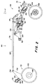
- the liftable wheel assembly 68 includes a front one Parallelogram suspension attached steering wheel assembly 70 and a rear swivel wheel assembly 72 formed by a Connection structure 74 are connected for synchronous operation. Although one with only a single pivot bearing Swivel wheel assembly is marked with 72, it should be noted that an assembly of the with a parallelogram suspension equipped type, which is essentially identical to that with 70 marked steering wheel assembly is in place of shown swivel wheel assembly 72 can be used.
- the swing lift wheel assembly 72 with a single one Swivel is less expensive and has if like below is attached, lifting and lowering properties described are approximated to those of the steering wheel assembly 70 so that the Frame 12 of the tillage implement 10 essentially from remains leveled front to rear when the wheel assemblies move vertically relative to the frame 12.
- the steering wheel assembly 70 includes a vertical one, as Attaching the wheel assembly to the frame end Fastening bracket 80, which is connected to the front tube 50 is connected.
- the rear ends are from the front rearward extending upper and lower links 86 and 88 are immediately in front of vertically offset points 90 and 92 the front surface of the tube 50 is pivotable with the bracket 80 connected.
- the front ends of links 86 and 88 are on vertically offset digits 96 and 98 at the rear end of an as Casting cast member 100 attached.
- the front end of the casting element 100 comprises a pivot bearing 102, the one steering arm 104 is pivotable about a vertical axis holds.
- the steering arm 104 extends from the pivot bearing 102 inwards and curved backwards and downwards at the Along side of a wheel 106 for connection to a hub 108 of the wheel 106.
- connection 88 is curved and opens above wheel 106 down to the steering movements of the steerable wheel 106 record when the tillage implement 10 is in the lowered position.
- the space between the outer perimeter of the wheel 106 and the underside of the connection 88 grows in the Direction of rotation R of the wheel 106 slightly so that the bottom the connection 88 near the mounting bracket 80 dirt and Contaminants scraped off in wet conditions can accumulate the wheel 106; the expanding space avoids wedging of remaining material between the wheel 106 and link 88.
- the liftable wheel assembly 68 is dimensioned such that the primary load of the Parallelogram suspension takes place through the lower connection 88, the upper link 86 being a substantially upright Orientation of the axis of the steerable wheel 106 is maintained.
- a pair of transversely spaced, as a lifting arm for a lifting cylinder 130 serving plates 110 is at the central portion of the screwed lower connection 88 and extends to both Top link 86 sides up.
- the plates 110 pivot with the lower link 88 and facilitate one Movement of top link 86 between plates 110 when the steering wheel assembly 70 is moved vertically.
- a rear, middle portion of plates 110 is slightly above that upper connection 86 with a piston rod side Attachment point 116 connected.
- the plates 110 extend further up from its middle section and behind to a mounting point 118 for the Connection structure 74.
- the attachment point 118 is direct above the fastening point 116 on the piston rod side arranged when the liftable wheel assembly 68 in the Transport position is ( Figure 1 and 2) and behind the Attachment point 116 when the liftable wheel assembly 68 in the field processing position shown in Figure 3.
- console 80 The upper portion of console 80 is with a second console 120 connected as an element for holding a drive serving lifting cylinder 130 is provided and located above the pipe 50 back and then back and down to one Connection with the front surface of the tube 62 extends which is attached by means of a U-bolt bracket 122.
- On serving as a connecting element cylinder fastening portion 124 extends from a rear portion of console 120 upwards and carries the piston chamber end of the lifting cylinder 130.
- the piston rod end of the lifting cylinder 130 is with connected to the piston rod-side fastening point 116.
- Extending the lifting cylinder 130 Figure 2 pivots the lower one Link 88 down to position 92 while retracting of the lifting cylinder 130 (FIG. 3) the lower connection 88 pivots above.
- the lift cylinder 130 extends parallel to the Frame portion to which it is attached and is opposite only slightly offset, both in the illustrated Extreme positions as well as in the intermediate positions to one to provide a very compact structure.
- the offset is the Fastening point 118 of the connection structure 74 opposite the Frame minimized upwards and the curved design of the trailing edges of panels 110 provides a compact Configuration of the plates 110, the lifting cylinder 130 and the Connection structure 74 in the field work position ( Figure 3) ready.
- the rear wheel assembly 72 includes a bracket 140 that is associated with the rear tube 52 is connected.
- the console 140 holds a wheel arm 144 about a pivot point at location 146 swiveling below and in front of the front surface of the tube 52 is arranged.
- the wheel arm 144 extends down and front ( Figure 2) to a hub 148 that a rear wheel 150 by transverse axis rotatably supports.
- a couple as Wheel connection with the steering wheel assembly 70 serving plates 156 are bolted to the sides of the wheel arm 144 and extend forward and upward (Figure 2) to an upper one End 158, which is above and in front of the tube 52 and in Essentially the same distance above the corresponding one Frame as the attachment point 118 on the plates 110 is arranged.
- a voltage connection 160 with adjustable Length extends between the attachment point 118 and the top end 158 and keeps the movement of the liftable Wheel structures 70 and 72 are substantially in line. As well in the extreme positions as well as every point in between the tension connection 160 close above the lift cylinder 130 and is only a short distance above the frame arranged.
- the tension connection 160 '( Figure 1) of the frame 12 is above frame 12 by plates 110 'and 116' which are slightly higher than the corresponding ones Plates 110 and 116 on the wing sections 42, 44 to the necessary freedom for the wing folding structures 46 and 48 to provide.
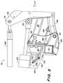
- a translator assembly 170 ( Figure 5) is between the second Console 120 and lower link 88 arranged to be a Feedback for an automatic depth control mechanism which may be essentially of the type that in US 5,957,218 A.
- the converter assembly 170 includes a rotary potentiometer 172 that has an arm 174 with a has outer end 176, the one marked with 178 Bow is movable.
- the outer end 176 is through a Connecting rod 180 on a pivot bearing at 184 with the lower link 88 connected, the pivot bearing 184 opposite the pivot axis at point 92 slightly forward offset and above the swivel axis at position 92 is arranged.
- the connecting rod 180 extends to Protection between opposite sides of the console 80.
- the Pivot point at 184 moves over an arc 188 when the lower link 88 from the transport position (shown) counterclockwise to the fully raised position panned.
- Points 176 and 184 are arranged such that arches 178 and 188 are substantially at the middle, above the Middle positions are centered around the movement of the Converter in the operating positions during the Maximize and linearize field operations.
- the configuration described above also protects the Converter assembly 170 since the components of the converter in short distance from the main components of the tillage implement 10 surrounded, but offset from it.
- Potentiometer 172 provides a wheel position signal to the depth control mechanism ready so the wheel position and depth of penetration of the Tools are selected and maintained automatically can.
- the wheel assembly 72 and the connection 74 with one essentially with the Wheel assembly 70 identical wheel assembly replaced and individually be controlled by the controller.
- the Mounting configuration for the wheel assembly 70 provides one Applicability of the lifting wheel assembly different locations of the frame ready to the desired To allow tool spacing on the pipes.
Landscapes
- Life Sciences & Earth Sciences (AREA)
- Zoology (AREA)
- Engineering & Computer Science (AREA)
- Mechanical Engineering (AREA)
- Soil Sciences (AREA)
- Environmental Sciences (AREA)
- Agricultural Machines (AREA)
- Transplanting Machines (AREA)
Abstract
Description
- Fig. 1
- eine perspektivische Frontansicht eines teilweise auseinandergefalteten, mit mehreren Abschnitten ausgestatteten Rahmens eines Bodenbearbeitungsgeräts mit einer erfindungsgemäßen Hubeinrichtung für die Räder,
- Fig. 2
- eine seitliche Ansicht der Hubeinrichtung der Räder, die am Flügelrahmen des Bodenbearbeitungsgeräts aus Figur 1 verwendet wird, wobei die Räder gegenüber dem Rahmen zum Transport abgesenkt sind,
- Fig. 3
- eine Seitenansicht ähnlich der in Figur 2, die jedoch die Räder in einer gegenüber dem Rahmen zur Feldarbeit angehobenen Stellung zeigt,
- Fig. 4
- eine Draufsicht auf die Hubeinrichtung der Räder der Figur 3, und
- Fig. 5
- eine vergrößerte seitliche Ansicht des Befestigungsbereichs der Hubeinrichtung der Räder am vorderen Abschnitt des Rahmens, in der Einzelheiten der Anbringung des Umsetzerzusammenbaus gezeigt werden.
Claims (11)
- Anhebbarer Radzusammenbau (36, 38, 66, 68) für den Rahmen (12, 42, 44) eines landwirtschaftlichen Geräts, insbesondere Bodenbearbeitungsgeräts (12), das zur Bewegung über den Erdboden eingerichtet ist, mit einer am Rahmen (12, 42, 44) anbringbaren Befestigung (80), einer Parallelogrammaufhängung, die eine untere Verbindung (88) und eine obere Verbindung (86) umfasst, wobei die untere Verbindung (88) und die obere Verbindung (86) erste Enden haben, die an der Befestigung (80) an vertikal versetzten Schwenkstellen schwenkbar angebracht sind, einer an zweiten, vertikal übereinander liegenden Enden der unteren Verbindung (88) und oberen Verbindung (86) schwenkbar angelenkten Radbefestigung (100), einem an der Radbefestigung (100) angebrachten, im Eingriff mit dem Erdboden befindlichen Rad (106), einem an der unteren Verbindung (88) befestigten, sich nach oben bis zu einem Endabschnitt oberhalb der oberen Verbindung (86) erstreckenden Hubarm (110), und einem am Endabschnitt des Hubarms (110) befestigten Antrieb (130), der betreibbar ist, die untere Verbindung (88) zwischen einer Transportposition und einer Feldarbeitsposition zu verschwenken.
- Radzusammenbau nach Anspruch 1, wobei die untere Verbindung (88) gekrümmt ist und sich von der oberen Verbindung nach unten öffnet und somit einen das Rad (106) aufnehmenden Raum unterhalb der Parallelogrammaufhängung definiert.
- Radzusammenbau nach Anspruch 2, wobei der das Rad (106) aufnehmende Raum in einem dem Umkreis des Rads (106) entsprechend gekrümmten Bogen gekrümmt und gegenüber dem Rad (106) versetzt ist, wobei sich der Abstand zwischen dem Rad (106) und der Verbindung (88) in Drehrichtung des Rads (106) vergrößert, um zu verhindern, dass sich Schmutz und Verunreinigungen zwischen dem Rad (106) und der Verbindung (88) ansammeln.
- Radzusammenbau nach einem der Ansprüche 1 bis 3, wobei sich der Antrieb (130) zwischen dem Endabschnitt und einem mit der Befestigung (80) verbundenen Element (120) erstreckt.
- Radzusammenbau nach einem der vorhergehenden Ansprüche, wobei ein in Vorwärtsbewegungsrichtung gegenüber dem Rad (106) versetztes, zweites Rad (150) vertikal schwenkbar am Rahmen (12, 42, 44) befestigt ist, und sich eine Radverbindung (156) vom zweiten Rad (150) nach oben erstreckt und mit dem zweiten Rad (150) schwenkbar ist, und eine sich von vorn nach hinten erstreckende Spannungsverbindung (160) die Radverbindung (156) und den Hubarm (110) verbindet.
- Radzusammenbau nach Anspruch 5, wobei eine Parallelogrammaufhängung das zweite Rad (150) mit dem Rahmen (12, 42, 44) verbindet.
- Radzusammenbau nach Anspruch 5, wobei ein einzelner Radarm (156) schwenkbar mit dem Rahmen (12, 42, 44) verbunden ist und das zweite Rad (150) um eine quer zur Vorwärtsbewegungsrichtung verlaufende Achse schwenkbar haltert.
- Radzusammenbau nach einem der Ansprüche 5 bis 7, wobei die Spannungsverbindung (160) und der Antrieb (130) über einen Betriebsbereich im Wesentlichen zueinander parallel verbleiben.
- Radzusammenbau nach einem der Ansprüche 4 bis 8, wobei die Befestigung (80) eine sich vom Rahmen nach oben erstreckende Konsole (120) und ein Verbindungselement (124) mit einem vorderen, an der Konsole (120) befestigten Ende sowie einem hinteren, mit dem Antrieb (130) verbundenen Ende umfasst, wobei der Antrieb (130) in im Wesentlichen paralleler Beziehung zum Rahmen (12, 42, 44) direkt über dem Rahmen (12, 42, 44) und unterhalb des oberen Endabschnitts des Hubarms (110) gehalten wird.
- Radzusammenbau nach einem der Ansprüche 1 bis 9, wobei der Antrieb (130) beim Zusammenziehen und Ausstrecken im Wesentlichen horizontal verbleibt.
- Radzusammenbau nach einem der Ansprüche 1 bis 10, wobei ein Umsetzerzusammenbau (170) zwischen dem Rahmen (12, 42, 44) und der unteren Verbindung (88) angeordnet ist, um eine Information über die Position des Rads (106) gegenüber dem Rahmen (12, 42, 44) zu erzeugen, wobei eine Verbindung (180) mit der unteren Verbindung (88) um einen Bogen (188) drehbar verbunden ist, dessen Mitte an der Schwenkstelle der unteren Verbindung (88) liegt, um die Bewegung des Umsetzers (172) zu maximieren und zu linearisieren und einen Schutz für den Umsetzer (172) bereitzustellen.
Applications Claiming Priority (2)
| Application Number | Priority Date | Filing Date | Title |
|---|---|---|---|
| US550979 | 2000-04-17 | ||
| US09/550,979 US6401832B1 (en) | 2000-04-17 | 2000-04-17 | Agricultural implement lift wheel structure |
Publications (2)
| Publication Number | Publication Date |
|---|---|
| EP1147699A1 true EP1147699A1 (de) | 2001-10-24 |
| EP1147699B1 EP1147699B1 (de) | 2005-11-09 |
Family
ID=24199339
Family Applications (1)
| Application Number | Title | Priority Date | Filing Date |
|---|---|---|---|
| EP01108800A Expired - Lifetime EP1147699B1 (de) | 2000-04-17 | 2001-04-07 | Anhebbarer Radzusammenbau für den Rahmen eines landwirtschaftlichen Geräts |
Country Status (8)
| Country | Link |
|---|---|
| US (1) | US6401832B1 (de) |
| EP (1) | EP1147699B1 (de) |
| AR (1) | AR033817A1 (de) |
| AU (1) | AU766963B2 (de) |
| BR (1) | BR0101480B1 (de) |
| CA (1) | CA2322576C (de) |
| DE (1) | DE50107944D1 (de) |
| UA (1) | UA71925C2 (de) |
Cited By (3)
| Publication number | Priority date | Publication date | Assignee | Title |
|---|---|---|---|---|
| EP1749427A1 (de) * | 2005-08-03 | 2007-02-07 | Amazonen-Werke H. Dreyer GmbH & Co. KG | Gezogenes landwirtschaftliches Gerät |
| WO2012092004A1 (en) * | 2010-12-29 | 2012-07-05 | Agco Corporation | Hydraulic walking beam |
| US20230413708A1 (en) * | 2022-06-22 | 2023-12-28 | Christian Kiel | Automatic Terrain Adjustment System for an Agricultural Implement |
Families Citing this family (24)
| Publication number | Priority date | Publication date | Assignee | Title |
|---|---|---|---|---|
| US6679339B1 (en) * | 2002-12-19 | 2004-01-20 | Deere & Company | Implement lift and level system with a front mounted direct coupled rockshaft |
| US6732812B1 (en) * | 2002-12-19 | 2004-05-11 | Deere & Company | Staggered frame element with overlap |
| US6745848B1 (en) * | 2003-02-06 | 2004-06-08 | Deere & Company | Tower and wheel arm assembly |
| US7543657B2 (en) * | 2004-08-25 | 2009-06-09 | Cnh Canada, Ltd. | Tillage apparatus having flexible frame and weight distribution system |
| US20080110649A1 (en) * | 2006-10-27 | 2008-05-15 | Deere And Company | Folding disk with wing stabilizer wheels |
| US7549482B2 (en) * | 2007-07-13 | 2009-06-23 | Cnh America Llc | Implement with two stage folding wing |
| US9148987B2 (en) * | 2012-04-12 | 2015-10-06 | Penta TMR Inc. | Agricultural caddy and trailer assembly |
| US8893816B2 (en) * | 2012-08-28 | 2014-11-25 | Deere & Company | Implement frame with main section helper lift cylinders |
| US9781872B2 (en) * | 2013-08-26 | 2017-10-10 | Great Plains Manufacturing, Inc. | Tillage implement with enhanced front wheel suspension |
| CA2867274C (en) * | 2013-11-13 | 2018-07-24 | Cnh Industrial America Llc | Agricultural tillage implement wheel control |
| RU2014144625A (ru) * | 2013-11-13 | 2016-05-27 | СиЭнЭйч ИНДАСТРИАЛ АМЕРИКА ЭлЭлСи | Система подъема качающегося рычага |
| US9622400B2 (en) * | 2013-11-13 | 2017-04-18 | Cnh Industrial America Llc | Agricultural tillage implement wheel control |
| US10420271B2 (en) | 2014-11-10 | 2019-09-24 | Cnh Industrial America Llc | Fully adjustable lift system |
| US10021822B2 (en) | 2015-06-30 | 2018-07-17 | Cnh Industrial America Llc | Mounted implement weight transfer |
| US10405479B2 (en) * | 2016-03-28 | 2019-09-10 | Kinze Manufacturing, Inc. | Mechanical cylinder synchronizer |
| US10159173B2 (en) | 2016-05-06 | 2018-12-25 | Cnh Industrial America Llc | Anti wobbling castor wheel configuration |
| US10645856B2 (en) * | 2017-04-28 | 2020-05-12 | Cnh Industrial America Llc | Remote hydraulic actuation and positioning of a plurality of implement stabilizer wheels |
| US20190098824A1 (en) * | 2017-09-29 | 2019-04-04 | Cnh Industrial America Llc | Systems and methods for an agricultural implement having pivoting stabilizer wheels |
| US10548255B2 (en) | 2017-11-01 | 2020-02-04 | Cnh Industrial Canada, Ltd. | Methods for reducing an overall transport profile of a multi-section tillage implement and related systems |
| US12133481B2 (en) * | 2017-12-14 | 2024-11-05 | Deere & Company | Stabilizer control for an agricultural implement |
| US10729054B2 (en) | 2018-02-07 | 2020-08-04 | Cnh Industrial America Llc | Tracked agricultural implement having a caster wheel assembly |
| WO2019200175A1 (en) * | 2018-04-12 | 2019-10-17 | Blount, Inc. | Regressive suspension spring system |
| CN109275399A (zh) * | 2018-11-28 | 2019-01-29 | 贵州大学 | 一种具有栽深自适应功能的移栽机 |
| CN113415117B (zh) * | 2021-05-14 | 2022-11-22 | 四川农业大学 | 一种小型底盘调平装置 |
Citations (5)
| Publication number | Priority date | Publication date | Assignee | Title |
|---|---|---|---|---|
| US3488064A (en) * | 1968-03-06 | 1970-01-06 | Allis Chalmers Mfg Co | Implement caster wheel |
| US3633679A (en) * | 1969-10-13 | 1972-01-11 | Fmc Corp | Mobile self-supporting tiller |
| FR2388475A2 (fr) * | 1975-06-17 | 1978-11-24 | Grudet Francois | Chassis porte-outils standards, semi-porte ou porte |
| US4655296A (en) * | 1985-02-15 | 1987-04-07 | F. P. Bourgault Industries, Ltd. | Farming implement with wheel depth control |
| US5957218A (en) | 1997-11-18 | 1999-09-28 | Deere & Company | Electrohydraulic control of implement lift cylinders |
Family Cites Families (12)
| Publication number | Priority date | Publication date | Assignee | Title |
|---|---|---|---|---|
| US3731749A (en) * | 1971-02-23 | 1973-05-08 | Deere & Co | Towed plow |
| JPS618138Y2 (de) * | 1980-08-26 | 1986-03-13 | ||
| CA1194728A (en) * | 1982-03-22 | 1985-10-08 | Albert K. Fuss | Trash seeder |
| US4693331A (en) * | 1986-04-23 | 1987-09-15 | Hiniker Company | Tractor boom |
| FR2622385B1 (fr) * | 1987-10-30 | 1991-05-10 | Cochet Const Machines Agricole | Perfectionnements aux dispositifs pour tasser le sol montes a l'avant d'un tracteur |
| US5011739A (en) * | 1989-10-02 | 1991-04-30 | Eastman Kodak Company | Moisture stable biasable transfer members and method for making same |
| US5228522A (en) * | 1991-07-01 | 1993-07-20 | Case Corporation | Lift assist and cushion spring tool bar wheel for agricultural implements |
| US5409069A (en) * | 1993-07-16 | 1995-04-25 | Kent Manufacturing, Co. | Tillage implement with gauge wheel linked to wing lifting and self-leveling mechanism |
| US6068062A (en) * | 1998-05-07 | 2000-05-30 | Deere & Company | Flexible frame for a multi-section implement |
| US5988293A (en) * | 1998-05-12 | 1999-11-23 | Deere & Company | Gauge structure for a cylinder operated depth control |
| US6098719A (en) * | 1998-12-02 | 2000-08-08 | Turner; James R. | Parallelogram boom devices for mounting agricultural implements to short wheel base tractors and adjusting implement position relative to ground |
| US6076611A (en) * | 1998-12-17 | 2000-06-20 | Agco Corporation | Implement mounted depth control system |
-
2000
- 2000-04-17 US US09/550,979 patent/US6401832B1/en not_active Expired - Lifetime
- 2000-10-06 CA CA002322576A patent/CA2322576C/en not_active Expired - Lifetime
-
2001
- 2001-04-07 EP EP01108800A patent/EP1147699B1/de not_active Expired - Lifetime
- 2001-04-07 DE DE50107944T patent/DE50107944D1/de not_active Expired - Lifetime
- 2001-04-16 BR BRPI0101480-3A patent/BR0101480B1/pt not_active IP Right Cessation
- 2001-04-17 AR ARP010101781A patent/AR033817A1/es active IP Right Grant
- 2001-04-17 UA UA2001042568A patent/UA71925C2/uk unknown
- 2001-04-17 AU AU35220/01A patent/AU766963B2/en not_active Ceased
Patent Citations (5)
| Publication number | Priority date | Publication date | Assignee | Title |
|---|---|---|---|---|
| US3488064A (en) * | 1968-03-06 | 1970-01-06 | Allis Chalmers Mfg Co | Implement caster wheel |
| US3633679A (en) * | 1969-10-13 | 1972-01-11 | Fmc Corp | Mobile self-supporting tiller |
| FR2388475A2 (fr) * | 1975-06-17 | 1978-11-24 | Grudet Francois | Chassis porte-outils standards, semi-porte ou porte |
| US4655296A (en) * | 1985-02-15 | 1987-04-07 | F. P. Bourgault Industries, Ltd. | Farming implement with wheel depth control |
| US5957218A (en) | 1997-11-18 | 1999-09-28 | Deere & Company | Electrohydraulic control of implement lift cylinders |
Cited By (4)
| Publication number | Priority date | Publication date | Assignee | Title |
|---|---|---|---|---|
| EP1749427A1 (de) * | 2005-08-03 | 2007-02-07 | Amazonen-Werke H. Dreyer GmbH & Co. KG | Gezogenes landwirtschaftliches Gerät |
| WO2012092004A1 (en) * | 2010-12-29 | 2012-07-05 | Agco Corporation | Hydraulic walking beam |
| US20230413708A1 (en) * | 2022-06-22 | 2023-12-28 | Christian Kiel | Automatic Terrain Adjustment System for an Agricultural Implement |
| US12317768B2 (en) * | 2022-06-22 | 2025-06-03 | Christian Kiel | Automatic terrain adjustment system for an agricultural implement |
Also Published As
| Publication number | Publication date |
|---|---|
| BR0101480A (pt) | 2001-11-13 |
| AU766963B2 (en) | 2003-10-30 |
| CA2322576A1 (en) | 2001-10-17 |
| AU3522001A (en) | 2001-10-18 |
| CA2322576C (en) | 2003-12-30 |
| DE50107944D1 (de) | 2005-12-15 |
| US6401832B1 (en) | 2002-06-11 |
| AR033817A1 (es) | 2004-01-07 |
| EP1147699B1 (de) | 2005-11-09 |
| UA71925C2 (en) | 2005-01-17 |
| BR0101480B1 (pt) | 2008-11-18 |
Similar Documents
| Publication | Publication Date | Title |
|---|---|---|
| EP1147699B1 (de) | Anhebbarer Radzusammenbau für den Rahmen eines landwirtschaftlichen Geräts | |
| DE2637444C2 (de) | Kombinierte Bodenbearbeitungsmaschine | |
| EP3122168B1 (de) | Bodenbearbeitungsgerät mit striegel- oder einebnungsvorrichtung | |
| CH650299A5 (de) | Schreitbagger. | |
| DE2922355A1 (de) | Aus ackerschlepper mit dreipunktanhaengung und kraftheber sowie einem anbaugeraet bestehende geraeteeinheit | |
| DE3107228C2 (de) | Anschluß- und Kupplungsvorrichtung für ein Arbeitsfahrzeug, insbesondere für einen Ackerschlepper | |
| DE2500857A1 (de) | Nutzfahrzeug mit mindestens einer hebevorrichtung | |
| DE2015792C2 (de) | Als Ackerschlepper einzusetzendes landwirtschaftliches Fahrzeug | |
| DE60112351T2 (de) | Heuwerbungsmaschine | |
| DE3133713C2 (de) | Vorrichtung zur Befestigung von Arbeitsgeräten an Fahrzeugen | |
| DE3632767A1 (de) | Kreiselheuwerbungsmaschine | |
| DE102020125047B3 (de) | Arbeitsmaschine | |
| DE69119491T2 (de) | Reinigungsfahrzeuge | |
| DE1482111A1 (de) | Anbauvorrichtung fuer den Seitenanbau von landwirtschaftlichen Geraeten an einen Ackerschlepper | |
| EP0571794B1 (de) | Landwirtschaftliche Arbeitsmaschine, besonders Kreiselheuwender | |
| DE3411161C2 (de) | ||
| DE3336313C2 (de) | Bodenstützgerät für eine Landmaschine | |
| CH622666A5 (en) | Working appliance for ground loosening which can be mounted on a tractor | |
| EP0955230B1 (de) | Arbeitsfahrzeug mit kippbarer Fahrerplattform und Kippvorrichtung | |
| EP0340539B1 (de) | Landwirtschaftliche Bestellkombination und Verfahren zu ihrem Ausheben | |
| DE202008014367U1 (de) | Heuwerbungsmaschine | |
| EP0427149B1 (de) | Vorrichtung zum Anbau einer Landmaschine an einen Dreipunktbock | |
| DE3337193C2 (de) | ||
| DE20012446U1 (de) | Landwirtschaftliche Maschine | |
| EP1444878B1 (de) | Aufbau für einen Radausleger und Stützträger |
Legal Events
| Date | Code | Title | Description |
|---|---|---|---|
| PUAI | Public reference made under article 153(3) epc to a published international application that has entered the european phase |
Free format text: ORIGINAL CODE: 0009012 |
|
| AK | Designated contracting states |
Kind code of ref document: A1 Designated state(s): DE FR GB Kind code of ref document: A1 Designated state(s): AT BE CH CY DE DK ES FI FR GB GR IE IT LI LU MC NL PT SE TR |
|
| AX | Request for extension of the european patent |
Free format text: AL;LT;LV;MK;RO;SI |
|
| 17P | Request for examination filed |
Effective date: 20020424 |
|
| AKX | Designation fees paid |
Free format text: DE FR GB |
|
| 17Q | First examination report despatched |
Effective date: 20031208 |
|
| GRAP | Despatch of communication of intention to grant a patent |
Free format text: ORIGINAL CODE: EPIDOSNIGR1 |
|
| GRAS | Grant fee paid |
Free format text: ORIGINAL CODE: EPIDOSNIGR3 |
|
| GRAA | (expected) grant |
Free format text: ORIGINAL CODE: 0009210 |
|
| AK | Designated contracting states |
Kind code of ref document: B1 Designated state(s): DE FR GB |
|
| REG | Reference to a national code |
Ref country code: GB Ref legal event code: FG4D Free format text: NOT ENGLISH |
|
| REF | Corresponds to: |
Ref document number: 50107944 Country of ref document: DE Date of ref document: 20051215 Kind code of ref document: P |
|
| GBT | Gb: translation of ep patent filed (gb section 77(6)(a)/1977) |
Effective date: 20051207 |
|
| ET | Fr: translation filed | ||
| PLBE | No opposition filed within time limit |
Free format text: ORIGINAL CODE: 0009261 |
|
| STAA | Information on the status of an ep patent application or granted ep patent |
Free format text: STATUS: NO OPPOSITION FILED WITHIN TIME LIMIT |
|
| 26N | No opposition filed |
Effective date: 20060810 |
|
| PGFP | Annual fee paid to national office [announced via postgrant information from national office to epo] |
Ref country code: GB Payment date: 20140428 Year of fee payment: 14 |
|
| GBPC | Gb: european patent ceased through non-payment of renewal fee |
Effective date: 20150407 |
|
| PG25 | Lapsed in a contracting state [announced via postgrant information from national office to epo] |
Ref country code: GB Free format text: LAPSE BECAUSE OF NON-PAYMENT OF DUE FEES Effective date: 20150407 |
|
| REG | Reference to a national code |
Ref country code: FR Ref legal event code: PLFP Year of fee payment: 16 |
|
| REG | Reference to a national code |
Ref country code: FR Ref legal event code: PLFP Year of fee payment: 17 |
|
| PGFP | Annual fee paid to national office [announced via postgrant information from national office to epo] |
Ref country code: FR Payment date: 20170426 Year of fee payment: 17 Ref country code: DE Payment date: 20170321 Year of fee payment: 17 |
|
| REG | Reference to a national code |
Ref country code: DE Ref legal event code: R119 Ref document number: 50107944 Country of ref document: DE |
|
| PG25 | Lapsed in a contracting state [announced via postgrant information from national office to epo] |
Ref country code: DE Free format text: LAPSE BECAUSE OF NON-PAYMENT OF DUE FEES Effective date: 20181101 |
|
| PG25 | Lapsed in a contracting state [announced via postgrant information from national office to epo] |
Ref country code: FR Free format text: LAPSE BECAUSE OF NON-PAYMENT OF DUE FEES Effective date: 20180430 |