EP1147040B1 - Dispositif de montage pour des organes de commande a pedale - Google Patents
Dispositif de montage pour des organes de commande a pedale Download PDFInfo
- Publication number
- EP1147040B1 EP1147040B1 EP99958255A EP99958255A EP1147040B1 EP 1147040 B1 EP1147040 B1 EP 1147040B1 EP 99958255 A EP99958255 A EP 99958255A EP 99958255 A EP99958255 A EP 99958255A EP 1147040 B1 EP1147040 B1 EP 1147040B1
- Authority
- EP
- European Patent Office
- Prior art keywords
- support plate
- mounting device
- face
- master cylinder
- pedal
- Prior art date
- Legal status (The legal status is an assumption and is not a legal conclusion. Google has not performed a legal analysis and makes no representation as to the accuracy of the status listed.)
- Expired - Lifetime
Links
- 239000012530 fluid Substances 0.000 claims description 76
- 238000010276 construction Methods 0.000 claims description 9
- 238000006073 displacement reaction Methods 0.000 claims description 9
- 238000007789 sealing Methods 0.000 claims description 8
- 230000009977 dual effect Effects 0.000 claims description 4
- 230000003014 reinforcing effect Effects 0.000 claims description 3
- 230000013011 mating Effects 0.000 claims 4
- 238000005266 casting Methods 0.000 claims 1
- 238000000465 moulding Methods 0.000 description 9
- 239000000463 material Substances 0.000 description 6
- 210000000056 organ Anatomy 0.000 description 6
- 239000004033 plastic Substances 0.000 description 5
- 229920003023 plastic Polymers 0.000 description 5
- 229910000838 Al alloy Inorganic materials 0.000 description 4
- 230000008901 benefit Effects 0.000 description 4
- 239000007788 liquid Substances 0.000 description 4
- 230000005540 biological transmission Effects 0.000 description 3
- 238000004891 communication Methods 0.000 description 3
- 229910052751 metal Inorganic materials 0.000 description 3
- 239000002184 metal Substances 0.000 description 3
- 239000000243 solution Substances 0.000 description 3
- 229910000831 Steel Inorganic materials 0.000 description 2
- 230000001133 acceleration Effects 0.000 description 2
- 238000006243 chemical reaction Methods 0.000 description 2
- 238000001514 detection method Methods 0.000 description 2
- 229920001971 elastomer Polymers 0.000 description 2
- 239000000806 elastomer Substances 0.000 description 2
- 239000012535 impurity Substances 0.000 description 2
- 238000002347 injection Methods 0.000 description 2
- 239000007924 injection Substances 0.000 description 2
- 238000009434 installation Methods 0.000 description 2
- 238000005192 partition Methods 0.000 description 2
- 230000000717 retained effect Effects 0.000 description 2
- 230000035945 sensitivity Effects 0.000 description 2
- 239000010959 steel Substances 0.000 description 2
- XLYOFNOQVPJJNP-UHFFFAOYSA-N water Substances O XLYOFNOQVPJJNP-UHFFFAOYSA-N 0.000 description 2
- QRYFCNPYGUORTK-UHFFFAOYSA-N 4-(1,3-benzothiazol-2-yldisulfanyl)morpholine Chemical compound C1COCCN1SSC1=NC2=CC=CC=C2S1 QRYFCNPYGUORTK-UHFFFAOYSA-N 0.000 description 1
- 208000031968 Cadaver Diseases 0.000 description 1
- 230000004323 axial length Effects 0.000 description 1
- 239000011324 bead Substances 0.000 description 1
- 238000005452 bending Methods 0.000 description 1
- 230000008859 change Effects 0.000 description 1
- 230000001143 conditioned effect Effects 0.000 description 1
- 239000004020 conductor Substances 0.000 description 1
- 230000007423 decrease Effects 0.000 description 1
- 230000007547 defect Effects 0.000 description 1
- 230000009429 distress Effects 0.000 description 1
- 230000000694 effects Effects 0.000 description 1
- 230000002349 favourable effect Effects 0.000 description 1
- 239000000945 filler Substances 0.000 description 1
- 239000012634 fragment Substances 0.000 description 1
- 230000005484 gravity Effects 0.000 description 1
- 238000010438 heat treatment Methods 0.000 description 1
- 238000003780 insertion Methods 0.000 description 1
- 230000037431 insertion Effects 0.000 description 1
- 210000002414 leg Anatomy 0.000 description 1
- 238000012423 maintenance Methods 0.000 description 1
- 238000000034 method Methods 0.000 description 1
- 230000010355 oscillation Effects 0.000 description 1
- 210000004417 patella Anatomy 0.000 description 1
- 238000011056 performance test Methods 0.000 description 1
- 230000002093 peripheral effect Effects 0.000 description 1
- 238000002360 preparation method Methods 0.000 description 1
- 238000003825 pressing Methods 0.000 description 1
- 238000012545 processing Methods 0.000 description 1
- 230000009467 reduction Effects 0.000 description 1
- 230000008439 repair process Effects 0.000 description 1
- 125000006850 spacer group Chemical group 0.000 description 1
- 230000002195 synergetic effect Effects 0.000 description 1
- 230000001052 transient effect Effects 0.000 description 1
- 238000003466 welding Methods 0.000 description 1
Images


Classifications
-
- G—PHYSICS
- G05—CONTROLLING; REGULATING
- G05G—CONTROL DEVICES OR SYSTEMS INSOFAR AS CHARACTERISED BY MECHANICAL FEATURES ONLY
- G05G1/00—Controlling members, e.g. knobs or handles; Assemblies or arrangements thereof; Indicating position of controlling members
- G05G1/30—Controlling members actuated by foot
- G05G1/36—Mounting units comprising an assembly of two or more pedals, e.g. for facilitating mounting
-
- B—PERFORMING OPERATIONS; TRANSPORTING
- B60—VEHICLES IN GENERAL
- B60T—VEHICLE BRAKE CONTROL SYSTEMS OR PARTS THEREOF; BRAKE CONTROL SYSTEMS OR PARTS THEREOF, IN GENERAL; ARRANGEMENT OF BRAKING ELEMENTS ON VEHICLES IN GENERAL; PORTABLE DEVICES FOR PREVENTING UNWANTED MOVEMENT OF VEHICLES; VEHICLE MODIFICATIONS TO FACILITATE COOLING OF BRAKES
- B60T7/00—Brake-action initiating means
- B60T7/02—Brake-action initiating means for personal initiation
- B60T7/04—Brake-action initiating means for personal initiation foot actuated
- B60T7/06—Disposition of pedal
Definitions
- the present invention applies to a mounting device of at least one pressure fluid control member operable by a pedal or lever for a motor vehicle and a driver's cab, comprising a support member in the form of a plate with two faces, respectively inner and outer with respect to said cabin, plate which carries the control member and its pedal (or lever) actuator and is capable of being fixed by at least a part of its periphery on the conjugate edge of an opening formed through a wall of said cabin.
- the present invention also relates to master cylinders integrated with a such a mounting device, and of course vehicles comprising such devices mounting.
- Pedal controllers for motor vehicles comprise generally, arranged from right to left, an accelerator control and a brake control generally operated in a non-simultaneous manner (except for special heel-toe control formerly used to downshift the ratios of transmission on competition cars) by the driver's right foot, and finally a clutch control (except for vehicles with automatic transmission) operated by the driver's left foot.
- clutter control devices is mainly conditioned by the clutter of the pedal itself whose positioning is studied with care, culminating most often to suspended pedals.
- pedal control for braking and disengaging generally include pressurized fluid valves, compressed air in general, whose bulk diametral not only is important but also tends to grow during the evolution of braking and declutching techniques.
- EP-A-550742 (US-A-5331813) an actuation assembly brakes, throttle and clutch of a vehicle, in which these three control elements are mounted on a common mounting plate in stamped sheet.
- Such a grouped assembly is mounted in a block in the vehicle by applying the mounting plate on the edge of an opening in a wall of the vehicle and fixing the plate by screws on this edge.
- the brake and clutch actuators of these vehicles are made of molded bodies made of resistant materials and which have a relatively high rigidity and it proved almost impossible to premount reliably, compactly and economically these bodies or control valves on sheet metal plates.
- the diameters of the movable piston parts of the valves and fluid pressure transmitters of these already relatively heavy heavy vehicles tend to increase to increase powers and sensitivities.
- the present invention therefore aims at producing a mounting device control devices of a vehicle actuated by a pedal or a lever which while being less cumbersome, less complex and therefore more reliable, presents decisive improvements in terms of the inherent rigidity and assembly of the control and ease of assembly of these organs, and which allows to reduce the cost of installing the function of the control devices in a cabin of vehicle driving, particularly in an industrial vehicle cabin.
- a mounting device of at least a pressurized fluid control device actuated by lever or pedal, for motor vehicle comprising a support in the general shape of a plate presenting two main faces, on which said fluid pressure control member having at least one main body made by molding, is arranged so as to cross the support plate from one main face to the other main face, said lever or associated pedal being mounted on the side of a first main face of the support, the characterized in that the support plate is formed rigid and monobloc by molding and in that the main body or assembly of the organ of pressurized fluid control is carried out in one piece with the support plate.
- the molded assembly (directly or, in the case of the possible use of plastic material, by performing an autogenous ultrasonic welding between at least two separately molded elements) one-piece consisting of at least the support plate and the main body of the control member can easily on the one hand be realized in a light and resistant material such as an aluminum alloy and, on the other hand, be provided with surfaces and elements (ribs) stiffening and ancillary elements (housings, bearings, guides) while all connecting elements (screws, bolts) that participate a lot of weighting and little stiffening are eliminated.
- ribs surfaces and elements
- ancillary elements housings, bearings, guides
- valve body or control members master cylinder
- At least one of the confinement walls of fluid of said pressurized fluid member is integrally formed with the support plate.
- said fluid control member pressure is a dual brake valve whose fluid fittings are arranged substantially parallel to the axis of symmetry of the double brake valve.
- said fluid control member pressure is a tandem brake valve whose first body is made monobloc with the support plate and has a receiving face of a second body reported.
- control member fluid under pressure is a master cylinder with hydraulic fluid
- at least a part of the body and / or the hydraulic fluid reserve container is made in one piece with the support plate.
- said reserve container is closed by a elastic bellows connected at one end to an annular rim of the reserve container and, at the other end, a pusher or movable plunger of the master cylinder through said reserve container.
- the piston of the master cylinder comprises a pusher which passes through said spare container and carries a seal annular lip which cooperates with the bore of the body of master-cylinder debouching on the inner wall of the reserve hydraulic fluid container, and at least one feedback groove is provided in the wall of said bore since the outlet in said wall of the container and extends axially in said wall of the bore beyond the inactive recoil position of the lip of the annular seal sealing, so as to allow direct refilling of the bore of the master cylinder by the hydraulic fluid of the reserve container via said groove when the piston of the master cylinder is in the recoil position.
- the piston of the master cylinder is constituted by a pusher which at one end carries a seal followed by a swivel bearing surface, always engaged in the bore inlet, even in position of said piston, and said pusher is connected to the other end of pivotally to an actuating member imposing said moving pusher axial pivoting on a small angle during said axial displacement.
- the body of the master cylinder and a part of the container are attached to the support plate in the area where the remainder of the reserve container, with interposition of a seal.
- the support plate also has the minus an electric and / or electronic control member and an associated pedal.
- said electric control member or electronics is mounted in a housing secured to a side face of the support plate, on the side of the first main face of the support plate turned into service to the passenger compartment of the vehicle.
- the electrical control member and / or electronics controls the engine accelerator of the vehicle.
- the support plate has, on the side of the first main face turned towards the cockpit, a box of connections in which are established electrical connections between at least one sensor cooperating with one of said control members and at least one connector passing through the support plate, said connection box can be made in one piece with the support.
- said connector opens, on the side of the second main face of the support plate, by a branch terminal and is capable of traversing the support plate substantially sealingly.
- connection box is closed, side of the first main face of the support plate, by a removable cover.
- the support plate has passages bulkhead for the passage of fluids and / or electrical connections from one main face to the other main face of the support plate.
- said lever or associated pedal is mounted pivoting on an axis carried by a bearing integrally formed with the support plate.
- said lever or associated pedal has a fork with hooked ends engaging in hooked openings conjugated made in a bearing formed integrally with the support and is easily removable.
- the support plate has, on the side of the second main face, a cavity in which is housed at least partially the pressurized fluid control member and at least one face of said cavity is provided with reinforcing ribs and / or stiffening.
- the support plate has at least one face adapted to be arranged contiguous with a conjugate face of the support plate of a other mounting device.
- the support plate has the general shape a rectangle with a flange on three of its sides intended to apply on the edge of an opening made in a wall of the vehicle, said face capable of being disposed contiguous with a conjugate face constituting the fourth side of the rectangle.
- the support plate has the general shape a rectangle on two opposite sides with a rim intended to apply on the edge of an opening made in one wall of the vehicle, the other two sides each constituting a face capable of being disposed contiguous with a conjugate face of the support plate of another mounting device.
- At least one face of the support plate has a seal capable of sealing between said support plate and a support plate joined rise of another mounting device.
- the master cylinder pressure generator hydraulic system is integrated into a main two-sided support plate, for constitute a mounting device according to the invention and the motor vehicle includes such a master cylinder.
- the motor vehicle includes two mounting devices, the first having a disengagement control and the second having a control valve of braking system and, where appropriate, in addition to an accelerator control engine.
- the motor vehicle comprises two devices of mounting which are arranged, with their respective support plates joined partially in an opening made in the wall of the driving cab of said vehicle.
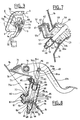
- FIG 1 we see in perspective the mounting device according to the invention in the position where it appears, seen from the driver's cab of the vehicle on which it is intended to be mounted.
- the basic element of this device is constituted by a plate-shaped support member 1 with two main faces, respectively one inner face and an outer face with respect to the driver's cab.
- the plate 1 here is subdivided into two half-plates 1a and 1b which are intended to be fixed joined by an outer flange or flange 2a and 2b respectively on the edge conjugate an opening 3 formed through the wall of the driver's cab (no represented) of the vehicle. It has been indicated in phantom in Figure 3, the edges 3b perpendicular and substantially rectangular openings 3 which cooperate with the mounting device of which only one half-plate is shown in this figure 3.
- the two half-plates 1a and 1b which, in some versions of the invention, can be replaced by a single plate 1, are made monoblock foundry molding, for example in die-cast aluminum alloy, and are joined substantially sealingly, by means of at least one joint continuous spacer 4 (see FIGS. 4 to 6), for example engaged in a groove provided on a half-plate and having a flexible outer bead coming to contact of a smooth conjugate face 5 of the other half-plate.
- Fixing two contiguous half-plates on the conjugate edge of the opening 3 formed through the the wall of the driver's cab is made for example by means of a crown of bolts (not shown in the figures) through holes 6 formed in the outer flange 2 and conjugate holes (not shown) provided on the edge of the opening 3 in the metal wall of the driver's cab.
- a flexible continuous seal 7 for example elastomer.
- the edges of the seal 7 which open on the junction face 5 of each semi-plates come for example in quasi-alignment, as we see in Figure 1.
- the flexible seal 7 is for example housed in a peripheral groove arranged on the face of the flange 2 in contact with the edge of the opening 3, or else it is glued on the face of the flange 2 to be inserted between this flange 2 and the edge conjugate of the opening 3.
- the plate 1 or the half-plates 1a and 1b carry by axle bearings 8 (only one is visible in Figure 1 and two are visible in FIG. 3), a pedal axle 9 on which is pivotally mounted, respectively a brake pedal 10a (interrupted to reveal the inside of a case connections) and a clutch pedal 10b.
- each of the half-plates 1a and 1b has its own pedal axis 9.
- the pedal axle 9 is replaced by the two branches of a fork whose ends in hook 11a and 11b engage in the openings in conjugate hooks 8a, 8b pedal support 8 to two amounts integral with the half-plate 1a.
- Each of the pedals 10 is connected, as shown in FIG. through a clevis 12 (see brake clevis 12a and the clutch cover 12b) to a respective control pusher (not shown in the figures) of a pressurized fluid valve, respectively of a brake control valve 13 and a clutch release valve 14.
- each of the control valves, brake valves 13 and clutch 14 is a control valve by emission of a fluid pressure and of which at least the main body and one of the fluid containment walls under pressure (15 for the brake control valve, see Figure 2) and / or reserve (for example reserve oil of a master cylinder 16 for controlling servo-clutch (see Figure 4), are made by one-piece moldings with the half plate that carries them.
- the containment walls of the reserve fluid in the case of the clutch control valve 14 with compressed air servo-assistance (wall containment 17) are located inside a monoblock housed 18 spare housing with the plate 1b and closed by a filler cap 19.
- connection terminals 24a, 24b and 24c see Figure 2.
- the two-sided plate 1 or at least one 1b half-plates carries reserved bulkhead passages 29.
- These bulkhead passages 29 allow the easy and / or tight crossing between the outside and the cabin of conducting a pressure fluid and / or electrical and / or electronic connection.
- Each bulkhead passage 29 can be closed by a plug 30 when it is not not used.
- FIG. 1 diagrammatically shows return springs 31a and 31b pedals 10a and 10b, constituted by traction springs, the spring of reminder of the accelerator pedal 10c not being visible in the throttle body 26.
- the control pedal of the fluid valves constituting the control members can also be recalled to the inactive position by the internal return spring at this control valve and acting on the actuating pusher of the valve, as is the case in the embodiment shown in Figure 3.
- FIG. 1 diagrammatically shows return springs 31a and 31b pedals 10a and 10b, constituted by traction springs, the spring of reminder of the accelerator pedal 10c not being visible in the throttle body 26.
- the control pedal of the fluid valves constituting the control members can also be recalled to the inactive position by the internal return spring at this control valve and acting on the actuating pusher of the valve, as is the case in the embodiment shown in Figure 3.
- the pedal 32 for actuating the control valve of disengagement is recalled in the inactive position by a pusher 33 for actuating the disengagement valve (the pusher 33 hidden by the pedal 32 is shown in dashed lines), himself recalled by an internal spring to the valve.
- This is precisely the strength of reaction transmitted to the pedal 32 by the pusher 33 which holds in position the ends 11a, 11b of the fork with two branches in contact with the openings in conjugate hook 8a, 8b of the pedal support 8.
- the pedal 10a or 10b When actuated by the driver of the vehicle, the pedal 10a or 10b causes a movement of the actuating pusher (not shown) of the valve of control 13 or 14 through the connecting yoke 12a, 12b, and the wheelhouse (not shown) actuated by this yoke is likely to excite respectively the sensor 22a indicating the beginning of the actuation of the brakes and the sensor 22b indicating that the clutch control performed the normal minimum run of walkout.
- FIG. 4 shows an exploded view of the two separate half-plates 1a and 1b and the accelerator control member 25 with its pedal 10c extracted from its housing accelerator 26 with its electrical and / or electronic connecting cable 21c which crosses a passage 34 formed in the bottom of the housing 26 to be placed inside of the connection box 20.
- the brake control valve 13b is here constituted by a double brake valve (with two parallel circuits actuated simultaneously).
- the body of this dual brake valve relatively wide important, is housed in a cavity 35 of the half-plate 1a, formed on the outside of this plate with reinforcing ribs or profiles 36 and / or stiffening.
- Another cavity 37 is provided for receiving a box of connections electric.
- the master cylinder 16 of disengagement control is housed partially in a cavity 38 arranged on the outer face of the plate 1b.
- the double brake valve 13b shown in FIG. exhaust 39 and fluid connection connections 40 which open on the face outer half-plate 1a and which are adapted to receive a fluid connection by plugging along an axis substantially parallel to the axis of symmetry of the tap of double brake 13b with two parallel pressure regulators.
- fluid connection fittings of the brake valve 13 which all open on the outer face of the half-plate 1a and for some, 40a, are oriented along the axis of the valve, and for others, 40b, are oriented perpendicular to the axis main brake valve 13.
- the body 13a of the brake valve 13 is integrally formed with the half-plate and is closed by an attached bottom 41 which has an exhaust connection 42.
- the half-plate shown in FIG. 6 a type brake valve is used. tandem or series, the valve body 13a of the first circuit brake valve is integrally formed with the half-plate 1a and has an assembly face 43 opening on the outside of the half-plate and on which is assembled and fixed by screws an extension valve body 44 constituting the control valve of the second brake circuit, with its exhaust connection 42 and its connections lateral power supply and output 40b.
- the device for mounting the pedal control of a vehicle in the general form of a two-sided plate, is consisting of two separate half-plates 1a, 1b, having a flange or flange of 2a, 2b on three sides out of four and may be attached to the wall of said driver's cab, contiguously substantially sealed by their sides without a fixing flange, to completely close said opening made to through a wall of the driver's cab.
- One, the, half-plates carries the valve 13, while the other half-plate 1b carries the valve of 14.
- Each half-plate bears on its inner face, the actuating pedal 10a, 10b of its control valve with the hinge pin 9 of this pedal arranged near a small side of the general rectangular shape half-plate.
- the half-plates 1a, 1b have on their inner face a shape in boss (see bosses 45 and 46 in FIG. 1) having an actuating passage 47 (in the boss 46 of FIG. 1), on the inside of the device, for the corresponding control valve for braking or disengaging.
- This passage actuator 47 is traversed by a valve actuating rod 48, 49 connected mechanically to the corresponding pedal 10a, 10b by the respective clevis 12a, 12b.
- the half plate 1 a carrying the brake valve 13 has a motor control 25 (accelerator) pivotable with its accelerator pedal 10c about an axis substantially parallel to the axis 9 of the braking and / or clutch pedals.
- the motor control 25, with its pedal 10c is mounted in a motor control box 26 secured to the wall side 27 of the half-plate 1a, which wall is formed near the long edge of the flange or flange 2a on the long side of the general rectangular shape of the half plate 1a carrying the brake valve.
- the engine control box 26 is thus located entirely on the inner face of the half-plate 1a carrying the valve braking system so as to protect the electronic throttle control against all the attacks likely to be caused by the external atmosphere.
- each of the half-plates 1a, 1b is equipped with its valve of respective command 13, 14 by acting on both sides of the half-plate then perfectly accessible and available.
- the wall 27 is then equipped with the throttle control 25 with its pedal 10c.
- the corresponding pedals 10a, 10b of the control valves 13, 14 by fluid emission are put in place, by connection with their pivot axis 9 and with the actuating linkage of valve via the yoke 12a and the actuating rods 48, 49, the stroke sensors or actuator being in position in contact with or near this wheelhouse.
- the different fluid connections: 40a, 40b on the side of the brake valve, 40c for the compressed air supply of the clutch assist valve, 40d for the disengaging hydraulic fluid supply, etc. are connected to corresponding fluids waiting outside the vehicle cab.
- external connection terminals 24a, 24b, 24c opening on the outer face are connected to wire bundles waiting outside the cab.
- the passages bulkhead 29 are optionally provided with a fluid or electrical circuit of crossing, after removal of their cap.
- an opening could be provided 3 of larger size and, where appropriate, a smaller gap between the pedals of brake 10a and accelerator 10c, so that the half-plates 1a and 1b can be mounted frontally through the opening 3 without having to first pass the pedals angled in the opening 3.
- the two half-plates la and 1b could also be replaced by a single plate in the manner already known in the construction of industrial vehicles.
- the advantage of using half plates la and 1b instead of a large unique plate lies in greater ease of mounting the valves of command and also in the possibility, in case of failure of one of the organs of control (braking, disengaging, accelerator), to quickly change the whole of the mounting plate that carries this failing organ, without having to proceed to tortuous disassembly.
- the plate or the half-mounting plates according to the invention may not include throttle control and may of course be arranged to make suspended pedals as partially shown in Figure 3, according to a solution considered the most comfortable for drivers and has the advantage of clearing the floor of the cabin driving the vehicle.
- FIG. 7 shows a mounting plate 1b intended for principle to be associated with a plate 1a (not shown) of control support brake and which is integrally formed with the cylinder body 50 of the master cylinder 52 and the body 51 of the reserve hydraulic liquid container.
- the body 51 of container actually consists of a cap and control part 51a which is realized monobloc, for example resistant plastic injection molded under pressure, and a portion 51b of capacity and settling.
- Part 51b of the body of container 51 is crossed, at an angle according to FIG. 7, by a pusher 53 of the piston 54 of the master cylinder.
- the piston 54 is, essentially, constituted of a filling lip seal 55 mounted in a manner retained by a central pin 56 at the end of the pusher 53.
- An elastic diaphragm 59 for example made of elastomer, is mounted tightly and relatively tightly, respectively on a flange 58 of the part 51b of container and a range 60 of the pusher 53.
- the cap portion 51a of container is closed by a screw cap 61 carrying electrodes 62 for controlling the level of the hydraulic fluid in the tank forming container 51, when this last is closed.
- the inner bore 63 (in principle raw of molding) of the body 50 of master cylinder has at least one axial groove 64 starting from the inlet (in principle slightly flared to facilitate the entry of the lip seal 55) of the bore 63 and extending for a sufficient length so that, in the maximum retracted position of the piston (inactive recoil position), as shown in FIG. 7, a communication is established between the inside 65 of the reserve container or reservoir 51 and the interior 66 of the cylindrical chamber of the master cylinder, to replenish a possible hydraulic fluid consumption of the master cylinder.
- the support plate 1b is example fixed on the wall of a vehicle cab, in the orientation represented by ratio to the vertical of the place, and the level 67 of the hydraulic liquid of the container 51 establishes itself as represented by placing in hydraulic load the lower part of diaphragm 59.
- the body of master cylinder 50 is connected by its connection 68 to a hydraulic circuit to be actuated, for example a hydropneumatic servo-clutch circuit with hydraulic tracking of the clutch stroke.
- the lip seal 55 exceeds the (where) the feedback grooves 64 and the inner chamber 66 of the bore 63 is then isolated and pressurized to discharge hydraulic fluid under pressure by the connection 68.
- the inactive recoil position as shown in FIG. Figure 7, if low hydraulic fluid consumption has occurred for various reasons (small leakage, wear of friction linings, transient heating of a part of the hydraulic circuit, etc.), a slight depression is established at the recoil of the lip seal 55 and sucks the liquid from the container 51 through the groove (s) 64 in the inner chamber 66 of the bore, and thence if necessary in the circuit hydraulic.
- the portion 51b of the tank body 51 has a inner settling capacity 65a, in which can be collected and stored the abrasive and corrosive impurities (water) of the hydraulic fluid in below the lowest axial groove 64, so that these impurities do not can never be sucked by the grooves 64 and injected into the hydraulic circuit from connection 68.
- FIG. 8 of a support plate 1b integrating a hydraulic master cylinder it is shown in side view the pedal actuator 69 mounted on an axis of rotation 70 and attached to a spring of pull 71 to return the piston 72 of the master cylinder 73 to the inactive position.
- the body of the master cylinder is here constituted of two assembled parts.
- the first part of the body of master cylinder is a tank body 74 of general shape cylindrical cut at an angle and come integrally by molding, for example here in cast aluminum alloy, with the remainder of the plate 1b having a square 75 of fixing the pedal pin 70 by means of two bearing lugs 76.
- second piece of the master-cylinder body is a tank-body bottom set cylinder 77 made in one piece, for example molded resistant plastics material by injection under pressure.
- the 77 cylinder tank-body bottom assembly is attached to the body of tank 74 and the support plate 1b, with the interposition of a seal 78 of ellipsoidal shape, because of the angled cut of the cylindrical tank body, by conventional fastening means such as screws, bolts, rivets of which only one of the 79 axes is shown.
- the bottom of reservoir 77 comprises two hydraulic fluid supply connectors 80 and 81 by gravity from a remotely located hydraulic fluid reservoir connected to the connection by a flexible tube.
- the hydraulic fluid reservoir is not shown in FIG. 8, where the connections 80 and 81 are closed each, in a delivery situation, by plugs 82.
- the cylinder body 50 of the one-piece assembly 77 is similar to the body of cylinder 50 shown in Figure 7 and it has, at the outlet of its bore 63 in the inner chamber 65 of the hydraulic fluid reservoir 74, 77, at least one groove 64 extending axially over a sufficient length in the bore 63 so that in the maximum retracted position of the piston 72 (inactive recoil position such shown in Figure 8), a communication is established between the interior 65 of the hydraulic fluid tank and the inside 66 of the pressure chamber of the body of cylinder 50, as in the embodiment shown in FIG. 7.
- the annular lip seal 55 is mounted in a groove ring 83 being retained by a central rim 56, in a manner similar to the embodiment shown in FIG. 7.
- the groove 83 which carries the seal is connected to a push rod 84, articulated at the end opposite the piston 72, to the actuating pedal 69, by a swivel bearing surface 85 constituted here for example by small lugs 85a, with an outer bearing surface of generally spherical shape.
- the surface swivel support 85 remains engaged in the bore 63 of the cylinder body, even in the maximum recoil position shown in FIG. 8.
- the axial grooves 64 for feeding must have an axial length slightly greater than the width of the lip 55 of the annular seal, increased by the width of the swivel bearing surface 85.
- the axial grooves 64 for ensure a safe supply, extend over the length L shown in the figure 8 and which substantially corresponds to the protruding length of the cylinder body 50 towards inside the tank chamber 65, from the partition 86 which connects the bottom of tank from the one-piece piece 77 to the tank body 50.
- the push rod 84 which passes through the cylindrical body 74 of the fluid reservoir hydraulic has a groove 88 for sealing the edge of a bellows 89 whose other edge is mounted on a sleeve 90 of the upper wall 91 of the body of reservoir 74.
- the sleeve 90 carries a recoil abutment shoulder 92 on the stem pusher 84 which has a conical ramp surface 93 cooperating with a operating tongue 94 of an electrical and / or electronic detection contact 95 actuating the master cylinder, engaged and / or snapped into a housing formed in the bracket 75 of the support plate 1b.
- the connection between the pedal 69 and the push rod 84 is made in this embodiment by a ball link 96 shown schematically in Figure 8.
- the center 97 of the patella moves thus on a circle 98 centered on the axis 70 when the pedal 69 is actuated (when press the pedal 69).
- the push rod 84 thus rotates a few degrees of angle which is rendered possible by the significant clearance between the bore through the partition 91 of the tank 74 (in fact in the sleeve 90) and the cylindrical portion 84a on the push rod 84.
- the push rod 84 pushes the gasket 55 downward, the outer sealing lip of this gasket insulating ring, after a very short stroke, the groove or grooves 64 of the chamber Inner 66 of the body 50 of the master cylinder.
- the hydraulic fluid contained in the cylinder chamber 66 is then on the one hand discharged by the connection 68 to one or several powered devices such as a hydro-pneumatic servo-clutch and on the other hand, pressurized by the axial force exerted on the piston 72.
- the tongue 94 passes contact with the conical ramp 93 in contact with the cylindrical surface 84a and actuates the actuating contact 95 which for example releases an actuating circuit transmission ratio switching.
- the hydraulic pressure prevailing in the chamber 66 vigorously pushes up the push rod 84 and after a certain return stroke of the piston 72, the pressure in the chamber 66 decreases makes pressure drops in the discharge pipes in connection with the connection 68 of the body 50.
- the traction return spring 71 then takes over to recall pedal 69 upwards and, via the ball link 96 effective in both directions, the push rod 84 and the piston 72 upwards.
- the refilling of the master cylinder 50 can be performed by all known means, instead of the axial grooves 64, and in particular by a bore or transverse passage which opens on the inner wall of the bore 63 and is closed by the axial displacement of the outer lip of the annular seal 55, or by making contact between a cylindrical pusher mirror polished and the inner lip of the annular seal 55.
- FIG. 8 makes it possible to use, for the realization of integrated master cylinder, the most suitable materials, the tank seals (seal ellipsoidal 78 and bellows 89) supporting at most one meter of water column pressure.
- the tank bottom part 77 and cylinder body is thus made of plastics with good mechanical resistance and good coefficient of friction
- the support plate 1b is for example made of aluminum alloy resistant, lightweight and easy to mold
- the push rod 84 and the pedal 69 are made of steel with a high resistance to tensile and compressive forces.
- the ball joint 96 can be made with a certain snapping effect.
- the range or opening of the ball 96a formed in the pedal body cut out of steel can be oriented in such a way that placing the push rod with its longitudinal axis 84b oriented substantially parallel to the long pedal arm (axis 69a), it is possible to engage by exerting a limited axial force, the ball head 84c formed on the push rod 84, in the ball socket cavity 96a.
- the push rod 84 is then returned to the position shown in Figure 8 by pivoting the ball joint 96, the head of 84c ball is then firmly snapped into the ball cavity 96a and an effort of Important reminder of the order of a few daN can be exerted on the push rod 84 by pulling on the ball joint 96 exerted by the return spring 71.
- connections 80 and 81 for connection to a hydraulic fluid reservoir are not not used or not provided, one could of course extend the hydraulic fluid reservoir inside 75a of the bracket 75 where appears an empty capacity available. He ... not However, the accessibility of connection areas such as connections 68, 80, 81 during the final assembly of the support plate 1b on the wall from the cab of a vehicle.
- the hydraulic pressure emitted at connection 68 of the cylinder body from a pedal control can be used for various purposes in a vehicle. actuation of a servo-clutch release member has already been mentioned, but it is obvious that the hydraulic pressure could actuate a braking circuit powered by a hydraulic or pneumatic pressure source acting as pilot pressure, for example for a braking circuit with anti-lock or anti-skidding called commonly "ABS braking".
- An interest of the provision of Figure 8 lies in the fact that if the emission capacity of the master cylinder body 50 is reduced (some cubic centimeters), it is possible to emit at high pressures, the order of a hundred bars, suitable for remote control (low loss relative load of the hydraulic displacement).
- the fluid reservoir hydraulic is space-saving and the risk of air return to piston return (significant risk for remote controls that create pressure drops opposing the rapid return of the hydraulic fluid) is practically nil.
- the body 50, 77 of the master cylinder and its flexible pipe connection pipe under pressure, as well as the flexible tube connecting to connection 80 or 81 (connected prior to the definitive placement of the support plate 1b), to stay in an inaccessible place where the elements are housed are made accessible by the removal of the support plate 1b.
- the pedal 69 could be replaced by a pedal similar to the pedal 32 and mounted like the latter by hooking on elements in the form of hooks, as shown in Figure 3.
Landscapes
- Engineering & Computer Science (AREA)
- Transportation (AREA)
- Mechanical Engineering (AREA)
- Physics & Mathematics (AREA)
- General Physics & Mathematics (AREA)
- Automation & Control Theory (AREA)
- Hydraulic Clutches, Magnetic Clutches, Fluid Clutches, And Fluid Joints (AREA)
- Braking Systems And Boosters (AREA)
- Arrangement And Mounting Of Devices That Control Transmission Of Motive Force (AREA)
- Regulating Braking Force (AREA)
- Braking Elements And Transmission Devices (AREA)
- Mechanical Control Devices (AREA)
Description
- la figure 1 représente en vue de dessus. c'est-à-dire en service du côté de la cabine de conduite, et en perspective un dispositif de montage selon l'invention, pour des organes de commande d'accélération, de freinage et de débrayage d'un véhicule industriel, la pédale de frein étant interrompue dans sa partie médiane pour laisser voir l'intérieur d'un boítier de connexions électriques ouvert ;
- la figure 2 représente en vue de dessous, c'est-à-dire en service du côté extérieur à la cabine de conduite, et en perspective, le dispositif de montage de la figure 1 ;
- la figure 3 représente en vue de dessus et donc, en service, de l'intérieur de la cabine de conduite, et en perspective, la moitié d'un dispositif de montage selon l'invention, placé en position relativement haute dans la cabine de conduite du véhicule, de manière que la pédale de commande amovible et/ou rapportée par accrochage, se trouve en position de "pédale suspendue" ;
- la figure 4 est une vue éclatée en perspective de dessous, et donc en service, de l'extérieur de la cabine, d'un autre mode de réalisation du dispositif de montage selon l'invention, avec deux plaques séparées dont l'une porte un maítre-cylindre d'actionnement de débrayage et l'autre porte un robinet de frein double, un espace ou boítier de connexions et une commande d'accélérateur (séparée latéralement) ;
- la figure 5 représente, en vue latérale et en perspective, la moitié d'un dispositif de montage selon l'invention portant un robinet de frein double et des connexions électriques ; et
- la figure 6 représente, en vue latérale semblable à celle de la figure 5, une moitié du dispositif de montage portant un robinet double tandem à corps rapporté et des connexions électriques,
- la figure 7 représente, en vue fragmentaire partiellement schématique et en coupe, un maítre-cylindre intégré à une plaque d'un dispositif de montage selon l'invention ;
- la figure 8 représente, en vue de côté et en coupe, un autre mode de réalisation d'une plaque d'un dispositif de montage selon l'invention intégrant un maítre-cylindre à piston oscillant.
- 21 a entre d'une part un capteur 22a coopérant avec la valve 13 de commande de freinage, par exemple un capteur de déplacement, et d'autre part un connecteur 23a ;
- 21b entre d'une part un capteur 22b coopérant avec la valve de débrayage 14, en fait ici de servo-débrayage, par exemple un capteur 22b de course de débrayage, et d'autre part un connecteur 23b ;
- 21c entre d'une part un capteur (non visible sur la figure 1) de commande d'accélération, par exemple un capteur électronique de l'angle de rotation de la pédale d'accélérateur 10c, et d'autre part un connecteur de moteur 23c. On notera que la pédale 10c actionne un organe de commande 25 électrique et/ou électronique du moteur du véhicule logé dans un boítier d'accélérateur 26 situé sur une face latérale 27 de la demi-plaque la et donc logé entièrement, y compris la liaison 21c de capteur, sur la face intérieure de la plaque 1a.
Claims (31)
- Dispositif de montage d'au moins un organe de commande à fluide sous pression (13, 14) actionné par levier ou pédale (10a, 10b, 32, 69), pour véhicule à moteur, comprenant un support (1) en forme générale de plaque, présentant deux faces principales, sur lequel ledit organe de commande à fluide sous pression présentant au moins un corps principal réalisé par moulage est agencé de sorte à traverser la plaque-support d'une face principale à l'autre face principale, ledit levier ou pédale associé étant monté du côté d'une première face principale de 1a plaque-support, caractérisé en ce que la plaque-support (1a, 1b) est formée rigide et monobloc par moulage et en ce que le corps principal ou d'assemblage (13a, 13b, 16, 50, 51, 74) de l'organe de commande à fluide sous pression (13, 14, 16, 52, 73) est réalisé monobloc avec la plaque-support (1a, 1b).
- Dispositif de montage selon la revendication 1, caractérisé en ce qu'au moins l'une (15, 17, 50, 51, 74) des parois de confinement de fluide dudit organe à fluide sous pression (13, 14, 52, 73) est réalisée monobloc avec la plaque-support (1).
- Dispositif de montage selon l'une quelconque des revendications 1 ou 2, caractérisé en ce que ledit levier ou pédale associé (10a, 10b, 10c, 69) est monté pivotant sur un axe (9, 70) porté par un palier (8, 76) formé monobloc avec la plaque-support (1).
- Dispositif de montage selon l'une quelconque des revendications 1 à 3, caractérisé en ce que ledit levier ou pédale associé (32) présente une fourche dont les extrémités en crochets (11a, 11b) s'engagent dans des ouvertures en crochets conjuguées (8a, 8b) réalisées dans un palier (8) formé monobloc avec la plaque-support.
- Dispositif de montage selon l'une des revendications 1 à 4, caractérisé en ce que ledit organe de commande à fluide sous pression est un robinet de frein double (13b) dont les raccords de fluide (40) sont disposés sensiblement parallèles à l'axe de symétrie du robinet de frein double.
- Dispositif de montage selon l'une des revendications 1 à 4, caractérisé en ce que ledit organe de commande à fluide sous pression est un robinet de frein tandem dont le corps principal (13a) est réalisé monobloc avec la plaque-support et présente une face (43) de réception d'un deuxième corps rapporté (44).
- Dispositif de montage selon l'une quelconque des revendications 1 à 6, dans lequel, de façon connue en soi, ledit organe de commande à fluide sous pression est un maítre-cylindre (52) à fluide hydraulique, caractérisé en ce qu'au moins une partie du corps (50) et/ou du récipient de réserve (51, 74) de fluide hydraulique est réalisée monobloc avec la plaque-support (1b).
- Dispositif de montage selon la revendication 7, caractérisé en ce que ledit récipient de réserve (51, 74) est fermé par un soufflet élastique (59, 89) relié, à une extrémité, à un rebord annulaire (58) du récipient de réserve (51) et, à l'autre extrémité, à un poussoir ou plongeur mobile (53, 84) du maítre-cylindre traversant ledit récipient de réserve.
- Dispositif de montage selon la revendication 7 ou 8, caractérisé en ce que le piston (54) du maítre-cylindre comporte un poussoir (53) qui traverse ledit récipient de réserve (51) et porte une garniture d'étanchéité annulaire à lèvre (55) qui coopère avec l'alésage (63) du corps de maítre-cylindre (50) débouchant sur la paroi intérieure du récipient (51) de fluide hydraulique de réserve, et en ce que au moins une rainure de réalimentation (64) est prévue dans la paroi dudit alésage depuis le débouché dans ladite paroi du récipient et s'étend axialement dans ladite paroi de l'alésage (63) jusqu'au delà de 1a position de recul inactive de la lèvre (55) de la garniture annulaire d'étanchéité, de manière à permettre la réalimentation directe de l'alésage (63) du maítre-cylindre par 1e liquide hydraulique du récipient de réserve (51) via ladite rainure (64) lorsque le piston du maítre-cylindre est en position de recul.
- Dispositif de montage selon l'une quelconque des revendications 7 à 9, caractérisé en ce que le piston du maítre-cylindre est constitué par un poussoir (84) qui porte à une extrémité une garniture d'étanchéité (55) suivie d'une surface d'appui rotulante (85, 85a) toujours engagée dans l'entrée de l'alésage (63), même en position de recul maximale dudit piston (72), et en ce que ledit poussoir (84) est relié, à l'autre extrémité de façon pivotante (96) à un organe d'actionnement (69) imposant audit poussoir en déplacement axial un pivotement sur un petit angle (arc 98) au cours dudit déplacement axial.
- Dispositif de montage selon l'une quelconque des revendications 7 à 10, caractérisé en ce que le corps (50) du maítre-cylindre et une partie (77) du récipient de réserve sont fixés sur la plaque-support (1b), dans la zone où est constitué le reste (74) du récipient de réserve, avec interposition d'un joint d'étanchéité (78).
- Dispositif de montage selon l'une quelconque des revendications 1 à 11, caractérisé en ce que la plaque-support (1a) présente en outre au moins un organe de commande électrique et/ou électronique (25) et une pédale associée (10c).
- Dispositif de montage selon la revendication 12, caractérisé en ce que ledit organe de commande électrique ou électronique est monté dans un boítier (26) solidaire d'une face latérale (27) de la plaque-support (1a), du côté de la première face principale de la plaque-support tournée en service vers l'habitacle du véhicule.
- Dispositif de montage selon l'une quelconque des revendications 12 ou 13, caractérisé en ce que l'organe de commande électrique et/ou électronique (25) commande l'accélérateur du moteur du véhicule.
- Dispositif de montage selon l'une quelconque des revendications 1 à 14, caractérisé en ce que 1a plaque-support (1a) présente, du côté de la première face principale tournée en service vers l'habitacle, un boítier de connexions (20) dans lequel sont établies des liaisons électriques (21a, 21b, 21c) entre au moins un capteur coopérant avec l'un desdits organes de commande (13, 14, 25) et au moins un connecteur (23a, 23b, 23c) traversant la plaque-support (1).
- Dispositif de montage selon la revendication 15, caractérisé en ce que ledit boítier de connexions (20) est réalisé monobloc avec la plaque-support.
- Dispositif de montage selon la revendication 15 ou 16, caractérisé en ce que ledit connecteur (23a, 23b, 23c) débouche, du côté de la deuxième face principale de la plaque-support (1a), par une borne de branchement (24a, 24b, 24c).
- Dispositif de montage selon l'une quelconque des revendications 15 à 17, caractérisé en ce que ledit connecteur (23a, 23b, 23c) traverse la plaque-support (1a) de façon sensiblement étanche.
- Dispositif de montage selon l'une quelconque des revendications 15 à 18, caractérisé en ce que ledit boítier de connexions (20) est fermé, du côté de la première face principale de la plaque-support (1), par un couvercle amovible (28).
- Dispositif de montage selon l'une quelconque des revendications 1 à 19, caractérisé en ce que la plaque-support (1b) présente des passages passe-cloison (29) permettant 1e passage de liaisons de fluides et/ou de liaisons électriques d'une face principale à l'autre face principale de la plaque-support (1b).
- Dispositif de montage selon l'une quelconque des revendications 1 à 20, caractérisé en ce que la plaque-support (1a, 1b) présente, du côté de la deuxième face principale, une cavité (35, 38) dans laquelle est logé au moins partiellement l'organe de commande à fluide sous pression (13, 14, 16).
- Dispositif de montage selon la revendication 21, caractérisé en ce qu'au moins une face de ladite cavité (35, 38) est munie de nervures de renforcement et/ou de raidissement (36).
- Dispositif de montage selon l'une quelconque des revendications 1 à 22, caractérisé en ce que la plaque-support (1a) présente au moins une face (5) apte à être disposée jointive avec une face conjuguée de la plaque-support (1b) d'un autre dispositif de montage.
- Dispositif de montage selon la revendication 23, caractérisé en ce que 1a plaque-support (1a, 1b) présente la forme générale d'un rectangle comportant sur trois de ses côtés un rebord (2a, 2b) destiné à s'appliquer sur le bord d'une ouverture (3) réalisée dans une paroi du véhicule, ladite face (5) apte à être disposée jointive avec une face conjuguée constituant le quatrième côté du rectangle.
- Dispositif de montage selon la revendication 23, caractérisé en ce que la plaque-support présente la forme générale d'un rectangle comportant sur deux côtés opposés un rebord (2a) destiné à s'appliquer sur le bord d'une ouverture (3) réalisée dans une paroi du véhicule, les deux autres côtés constituant chacun une face (5) apte à être disposée jointive avec une face conjuguée de la plaque-support d'un autre dispositif de montage.
- Dispositif de montage selon l'une quelconque des revendications 23 à 25, caractérisé en ce que au moins une face (5) de la plaque-support (1a) présente un joint (4) apte à assurer l'étanchéité entre ladite plaque-support (1a) et une plaque-support (1b) montée jointive d'un autre dispositif de montage.
- Maítre cylindre générateur de pression hydraulique, caractérisé en ce que le corps principal ou d'assemblage du maítre cylindre est réalisé monobloc avec une plaque-support (1b) en forme de plaque à deux faces principales dans laquelle est intégrée la pédale d'actionnement (10b, 69), pour constituer un dispositif de montage selon l'une quelconque des revendications 7 à 11.
- Véhicule à moteur comprenant au moins un dispositif de montage selon l'une quelconque des revendications 1 à 26 ou un maítre cylindre selon la revendication 27.
- Véhicule à moteur selon la revendication 28, caractérisé en ce qu'il comprend deux dispositifs de montage, le premier présentant un organe de commande de débrayage (14) et le deuxième présentant une valve de commande à fluide sous pression (13).
- Véhicule à moteur selon la revendication 29, caractérisé en ce que ledit deuxième dispositif de montage présente en outre un organe de commande (25) d'accélérateur du moteur.
- Véhicule à moteur selon l'une quelconque des revendications 28 à 30, caractérisé en ce que deux dispositifs de montage sont disposés avec leurs plaques-supports respectives (1a, 1b) jointives partiellement dans une ouverture (3) réalisée dans la paroi de la cabine de conduite dudit véhicule.
Applications Claiming Priority (3)
| Application Number | Priority Date | Filing Date | Title |
|---|---|---|---|
| FR9815682 | 1998-12-11 | ||
| FR9815682A FR2787211B1 (fr) | 1998-12-11 | 1998-12-11 | Dispositif de montage pour des organes de commande a pedale |
| PCT/FR1999/003033 WO2000035727A1 (fr) | 1998-12-11 | 1999-12-07 | Dispositif de montage pour des organes de commande a pedale |
Publications (2)
| Publication Number | Publication Date |
|---|---|
| EP1147040A1 EP1147040A1 (fr) | 2001-10-24 |
| EP1147040B1 true EP1147040B1 (fr) | 2004-03-03 |
Family
ID=9533883
Family Applications (1)
| Application Number | Title | Priority Date | Filing Date |
|---|---|---|---|
| EP99958255A Expired - Lifetime EP1147040B1 (fr) | 1998-12-11 | 1999-12-07 | Dispositif de montage pour des organes de commande a pedale |
Country Status (6)
| Country | Link |
|---|---|
| EP (1) | EP1147040B1 (fr) |
| AT (1) | ATE260792T1 (fr) |
| AU (1) | AU1566400A (fr) |
| DE (1) | DE69915368T2 (fr) |
| FR (1) | FR2787211B1 (fr) |
| WO (1) | WO2000035727A1 (fr) |
Cited By (1)
| Publication number | Priority date | Publication date | Assignee | Title |
|---|---|---|---|---|
| EP4307076A1 (fr) * | 2022-07-14 | 2024-01-17 | KNORR-BREMSE Systeme für Nutzfahrzeuge GmbH | Pédale |
Families Citing this family (15)
| Publication number | Priority date | Publication date | Assignee | Title |
|---|---|---|---|---|
| DE19934238C1 (de) | 1999-07-21 | 2001-01-25 | Fte Automotive Gmbh | Vorrichtung zur Betätigung einer Kupplung, insbesondere für Kraftfahrzeuge |
| JP2004528821A (ja) * | 2000-12-07 | 2004-09-24 | シンジェンタ リミテッド | 除草剤抵抗性植物 |
| DE10330893A1 (de) * | 2003-07-09 | 2005-02-10 | Daimlerchrysler Ag | Pedallagerbock |
| EP1754641A3 (fr) * | 2005-08-20 | 2009-02-18 | LuK Lamellen und Kupplungsbau Beteiligungs KG | Dispositif pour actionnement d'embrayage |
| DE102005062390B4 (de) * | 2005-12-23 | 2019-06-27 | Iveco Magirus Ag | Fußhebelbock für Lkw-Fahrerkabine |
| DE102007059376A1 (de) * | 2007-12-10 | 2009-06-18 | Volkswagen Ag | Modulares Fußhebelwerk |
| DE102008037923A1 (de) * | 2008-08-14 | 2010-02-18 | Bayerische Motoren Werke Aktiengesellschaft | Bremsbetätigungsvorrichtung eines Fahrzeugs |
| DE102009019642A1 (de) * | 2009-04-30 | 2010-11-04 | Volkswagen Ag | Einrichtung zur Betätigung einer hydraulischen Kupplung eines Kraftfahrzeugs und Montageverfahren dazu |
| WO2014033930A1 (fr) * | 2012-08-31 | 2014-03-06 | 株式会社ヨロズ | Dispositif de pédale de frein et procédé de fixation pour celle-ci |
| DE112014005326A5 (de) | 2013-11-22 | 2016-08-18 | Schaeffler Technologies AG & Co. KG | Pedalintegrierter Kupplungsgeberzylinder |
| DE102014217199B3 (de) * | 2014-08-28 | 2016-01-14 | Ford Global Technologies, Llc | Kupplungspedalsystem sowie Geberzylinder für ein Kupplungspedalsystem eines Fahrzeugs |
| CN108137003B (zh) | 2015-09-18 | 2020-06-30 | 康斯博格动力产品系统一号股份有限公司 | 具有相同的第一壳体部件和第二壳体部件的踏板组件 |
| WO2017049099A1 (fr) | 2015-09-18 | 2017-03-23 | Kongsberg Power Products Systems I, Inc. | Ensemble pédale à mécanisme de filtration de débris |
| DE102023115822B4 (de) * | 2023-06-16 | 2025-03-27 | Daimler Truck AG | Verbindungsanordnung eines Betätigungselements an einem Bremspedal für ein Kraftfahrzeug, insbesondere für ein Nutzfahrzeug |
| CN119116898B (zh) * | 2024-11-12 | 2025-04-25 | 上海谋行科技有限公司 | 一种兼容鼓式制动器与盘式制动器的商用车emb系统 |
Family Cites Families (2)
| Publication number | Priority date | Publication date | Assignee | Title |
|---|---|---|---|---|
| DE9109689U1 (de) * | 1991-08-05 | 1992-12-03 | Lucas Industries Plc, Solihull, West Midlands | Bremsbetätigungsbaugruppe für Kraftfahrzeuge |
| DE4304565A1 (de) * | 1993-02-16 | 1994-08-18 | Teves Gmbh Alfred | Hydraulische Kraftfahrzeugbremsanlage |
-
1998
- 1998-12-11 FR FR9815682A patent/FR2787211B1/fr not_active Expired - Lifetime
-
1999
- 1999-12-07 DE DE69915368T patent/DE69915368T2/de not_active Expired - Lifetime
- 1999-12-07 AT AT99958255T patent/ATE260792T1/de not_active IP Right Cessation
- 1999-12-07 AU AU15664/00A patent/AU1566400A/en not_active Abandoned
- 1999-12-07 WO PCT/FR1999/003033 patent/WO2000035727A1/fr not_active Ceased
- 1999-12-07 EP EP99958255A patent/EP1147040B1/fr not_active Expired - Lifetime
Cited By (2)
| Publication number | Priority date | Publication date | Assignee | Title |
|---|---|---|---|---|
| EP4307076A1 (fr) * | 2022-07-14 | 2024-01-17 | KNORR-BREMSE Systeme für Nutzfahrzeuge GmbH | Pédale |
| EP4307077A1 (fr) * | 2022-07-14 | 2024-01-17 | KNORR-BREMSE Systeme für Nutzfahrzeuge GmbH | Dispositif de pédale |
Also Published As
| Publication number | Publication date |
|---|---|
| AU1566400A (en) | 2000-07-03 |
| FR2787211A1 (fr) | 2000-06-16 |
| DE69915368T2 (de) | 2005-02-17 |
| EP1147040A1 (fr) | 2001-10-24 |
| DE69915368D1 (de) | 2004-04-08 |
| WO2000035727A1 (fr) | 2000-06-22 |
| ATE260792T1 (de) | 2004-03-15 |
| FR2787211B1 (fr) | 2001-03-09 |
Similar Documents
| Publication | Publication Date | Title |
|---|---|---|
| EP1147040A1 (fr) | Dispositif de montage pour des organes de commande a pedale | |
| EP2445767B1 (fr) | Systeme de freins a servofrein electrique | |
| FR2615811A1 (fr) | Dispositif d'actionnement de freins pour vehicule automobile | |
| FR2818944A1 (fr) | Installation de freinage hydraulique pour vehicule comportant un simulateur actif | |
| EP2437963B1 (fr) | Systeme de freins a maître-cylindre, decouple de la pedale de frein et servofrein hydraulique | |
| FR2504877A1 (fr) | Maitre-cylindre pour freins hydrauliques de vehicule automobile | |
| EP0214000B1 (fr) | Compensateur automatique d'usure pour embrayage de véhicule automobile | |
| FR2467752A1 (fr) | Systeme de freinage hydraulique | |
| FR2480692A1 (fr) | Dispositif de commande pour le mecanisme a soupape d'un servofrein | |
| FR2516463A1 (fr) | Systeme pneumatique de freinage de vehicule et dispositif de surete pour un tel systeme | |
| FR2481216A1 (fr) | Servo-moteur d'assistance au freinage a renfort de fixation | |
| FR2550149A1 (fr) | Generateur de pression de freinage pour systeme de freinage de vehicule | |
| FR2578213A1 (fr) | Systeme de freinage hydraulique | |
| FR2796174A1 (fr) | Dispositif de montage pour au moins un organe de commande a pedale | |
| EP1519865A1 (fr) | Reservoir de liquide hydraulique. | |
| FR2482028A1 (fr) | Amplificateur de force de freinage commande mecaniquement notamment pour vehicules automobiles | |
| EP0923017B1 (fr) | Dispositif de commande au pied d'un système tel qu'un système d'assistance au freinage d'un véhicule automobile | |
| FR2636574A1 (en) | Vehicle provided with a main clutch of the oil type, particularly for tractors, particularly civil engineering tractors | |
| EP0186580B1 (fr) | Servomoteur à fluide sous pression | |
| FR2990256A1 (fr) | Emetteur hydraulique a triple chambre pour commande d'embrayage et procedes associes | |
| EP1847431A1 (fr) | Servomoteur d'assistance pneumatique de freinage d'un véhicule et procédé de montage d'une tige de commande de frein associé | |
| EP0368701B2 (fr) | Système de freinage hydraulique assisté, et servomoteur d'assistance et valve de commande adaptes a un tel système | |
| WO2010007101A1 (fr) | Dispositif d'assistance hydraulique de freinage | |
| EP3635272B1 (fr) | Vehicule automobile equipee d'un dispositif hydraulique de controle comprenant une commande | |
| WO1979000392A1 (fr) | Dispositif transformateur d'efforts |
Legal Events
| Date | Code | Title | Description |
|---|---|---|---|
| PUAI | Public reference made under article 153(3) epc to a published international application that has entered the european phase |
Free format text: ORIGINAL CODE: 0009012 |
|
| 17P | Request for examination filed |
Effective date: 20010711 |
|
| AK | Designated contracting states |
Kind code of ref document: A1 Designated state(s): AT BE CH CY DE DK ES FI FR GB GR IE IT LI LU MC NL PT SE |
|
| AX | Request for extension of the european patent |
Free format text: AL;LT;LV;MK;RO;SI |
|
| 17Q | First examination report despatched |
Effective date: 20021030 |
|
| GRAP | Despatch of communication of intention to grant a patent |
Free format text: ORIGINAL CODE: EPIDOSNIGR1 |
|
| GRAS | Grant fee paid |
Free format text: ORIGINAL CODE: EPIDOSNIGR3 |
|
| GRAA | (expected) grant |
Free format text: ORIGINAL CODE: 0009210 |
|
| AK | Designated contracting states |
Kind code of ref document: B1 Designated state(s): AT BE CH CY DE DK ES FI FR GB GR IE IT LI LU MC NL PT SE |
|
| PG25 | Lapsed in a contracting state [announced via postgrant information from national office to epo] |
Ref country code: IE Free format text: LAPSE BECAUSE OF FAILURE TO SUBMIT A TRANSLATION OF THE DESCRIPTION OR TO PAY THE FEE WITHIN THE PRESCRIBED TIME-LIMIT Effective date: 20040303 Ref country code: GB Free format text: LAPSE BECAUSE OF FAILURE TO SUBMIT A TRANSLATION OF THE DESCRIPTION OR TO PAY THE FEE WITHIN THE PRESCRIBED TIME-LIMIT Effective date: 20040303 Ref country code: FI Free format text: LAPSE BECAUSE OF FAILURE TO SUBMIT A TRANSLATION OF THE DESCRIPTION OR TO PAY THE FEE WITHIN THE PRESCRIBED TIME-LIMIT Effective date: 20040303 Ref country code: CY Free format text: LAPSE BECAUSE OF FAILURE TO SUBMIT A TRANSLATION OF THE DESCRIPTION OR TO PAY THE FEE WITHIN THE PRESCRIBED TIME-LIMIT Effective date: 20040303 Ref country code: AT Free format text: LAPSE BECAUSE OF FAILURE TO SUBMIT A TRANSLATION OF THE DESCRIPTION OR TO PAY THE FEE WITHIN THE PRESCRIBED TIME-LIMIT Effective date: 20040303 |
|
| REG | Reference to a national code |
Ref country code: GB Ref legal event code: FG4D Free format text: NOT ENGLISH |
|
| REG | Reference to a national code |
Ref country code: CH Ref legal event code: EP |
|
| REG | Reference to a national code |
Ref country code: IE Ref legal event code: FG4D Free format text: FRENCH |
|
| REF | Corresponds to: |
Ref document number: 69915368 Country of ref document: DE Date of ref document: 20040408 Kind code of ref document: P |
|
| PG25 | Lapsed in a contracting state [announced via postgrant information from national office to epo] |
Ref country code: GR Free format text: LAPSE BECAUSE OF FAILURE TO SUBMIT A TRANSLATION OF THE DESCRIPTION OR TO PAY THE FEE WITHIN THE PRESCRIBED TIME-LIMIT Effective date: 20040603 Ref country code: DK Free format text: LAPSE BECAUSE OF FAILURE TO SUBMIT A TRANSLATION OF THE DESCRIPTION OR TO PAY THE FEE WITHIN THE PRESCRIBED TIME-LIMIT Effective date: 20040603 |
|
| REG | Reference to a national code |
Ref country code: SE Ref legal event code: TRGR |
|
| PG25 | Lapsed in a contracting state [announced via postgrant information from national office to epo] |
Ref country code: ES Free format text: LAPSE BECAUSE OF FAILURE TO SUBMIT A TRANSLATION OF THE DESCRIPTION OR TO PAY THE FEE WITHIN THE PRESCRIBED TIME-LIMIT Effective date: 20040614 |
|
| LTIE | Lt: invalidation of european patent or patent extension |
Effective date: 20040303 |
|
| GBV | Gb: ep patent (uk) treated as always having been void in accordance with gb section 77(7)/1977 [no translation filed] |
Effective date: 20040303 |
|
| REG | Reference to a national code |
Ref country code: IE Ref legal event code: FD4D |
|
| PG25 | Lapsed in a contracting state [announced via postgrant information from national office to epo] |
Ref country code: LU Free format text: LAPSE BECAUSE OF NON-PAYMENT OF DUE FEES Effective date: 20041207 |
|
| PG25 | Lapsed in a contracting state [announced via postgrant information from national office to epo] |
Ref country code: MC Free format text: LAPSE BECAUSE OF NON-PAYMENT OF DUE FEES Effective date: 20041231 Ref country code: LI Free format text: LAPSE BECAUSE OF NON-PAYMENT OF DUE FEES Effective date: 20041231 Ref country code: CH Free format text: LAPSE BECAUSE OF NON-PAYMENT OF DUE FEES Effective date: 20041231 |
|
| PLBE | No opposition filed within time limit |
Free format text: ORIGINAL CODE: 0009261 |
|
| STAA | Information on the status of an ep patent application or granted ep patent |
Free format text: STATUS: NO OPPOSITION FILED WITHIN TIME LIMIT |
|
| 26N | No opposition filed |
Effective date: 20041206 |
|
| REG | Reference to a national code |
Ref country code: CH Ref legal event code: PL |
|
| PG25 | Lapsed in a contracting state [announced via postgrant information from national office to epo] |
Ref country code: PT Free format text: LAPSE BECAUSE OF NON-PAYMENT OF DUE FEES Effective date: 20040803 |
|
| REG | Reference to a national code |
Ref country code: FR Ref legal event code: PLFP Year of fee payment: 17 |
|
| REG | Reference to a national code |
Ref country code: FR Ref legal event code: PLFP Year of fee payment: 18 |
|
| REG | Reference to a national code |
Ref country code: FR Ref legal event code: PLFP Year of fee payment: 19 |
|
| PGFP | Annual fee paid to national office [announced via postgrant information from national office to epo] |
Ref country code: SE Payment date: 20181211 Year of fee payment: 20 Ref country code: NL Payment date: 20181213 Year of fee payment: 20 |
|
| PGFP | Annual fee paid to national office [announced via postgrant information from national office to epo] |
Ref country code: BE Payment date: 20181023 Year of fee payment: 20 Ref country code: FR Payment date: 20181206 Year of fee payment: 20 |
|
| PGFP | Annual fee paid to national office [announced via postgrant information from national office to epo] |
Ref country code: IT Payment date: 20181220 Year of fee payment: 20 Ref country code: DE Payment date: 20181221 Year of fee payment: 20 |
|
| REG | Reference to a national code |
Ref country code: DE Ref legal event code: R071 Ref document number: 69915368 Country of ref document: DE |
|
| REG | Reference to a national code |
Ref country code: NL Ref legal event code: MK Effective date: 20191206 |
|
| REG | Reference to a national code |
Ref country code: BE Ref legal event code: MK Effective date: 20191207 |
|
| REG | Reference to a national code |
Ref country code: SE Ref legal event code: EUG |