EP1146992B1 - Schweissmaschine - Google Patents
Schweissmaschine Download PDFInfo
- Publication number
- EP1146992B1 EP1146992B1 EP00900272A EP00900272A EP1146992B1 EP 1146992 B1 EP1146992 B1 EP 1146992B1 EP 00900272 A EP00900272 A EP 00900272A EP 00900272 A EP00900272 A EP 00900272A EP 1146992 B1 EP1146992 B1 EP 1146992B1
- Authority
- EP
- European Patent Office
- Prior art keywords
- subframe
- welding machine
- internal pipe
- articulation
- pipe welding
- Prior art date
- Legal status (The legal status is an assumption and is not a legal conclusion. Google has not performed a legal analysis and makes no representation as to the accuracy of the status listed.)
- Expired - Lifetime
Links
Images


Classifications
-
- B—PERFORMING OPERATIONS; TRANSPORTING
- B23—MACHINE TOOLS; METAL-WORKING NOT OTHERWISE PROVIDED FOR
- B23K—SOLDERING OR UNSOLDERING; WELDING; CLADDING OR PLATING BY SOLDERING OR WELDING; CUTTING BY APPLYING HEAT LOCALLY, e.g. FLAME CUTTING; WORKING BY LASER BEAM
- B23K37/00—Auxiliary devices or processes, not specially adapted for a procedure covered by only one of the other main groups of this subclass
- B23K37/04—Auxiliary devices or processes, not specially adapted for a procedure covered by only one of the other main groups of this subclass for holding or positioning work
- B23K37/053—Auxiliary devices or processes, not specially adapted for a procedure covered by only one of the other main groups of this subclass for holding or positioning work aligning cylindrical work; Clamping devices therefor
- B23K37/0531—Internal pipe alignment clamps
-
- B—PERFORMING OPERATIONS; TRANSPORTING
- B23—MACHINE TOOLS; METAL-WORKING NOT OTHERWISE PROVIDED FOR
- B23K—SOLDERING OR UNSOLDERING; WELDING; CLADDING OR PLATING BY SOLDERING OR WELDING; CUTTING BY APPLYING HEAT LOCALLY, e.g. FLAME CUTTING; WORKING BY LASER BEAM
- B23K2101/00—Articles made by soldering, welding or cutting
- B23K2101/04—Tubular or hollow articles
- B23K2101/06—Tubes
Definitions
- the present invention relates to internal pipe welding machines.
- Known internal pipe welding machines include a chassis having a front subframe of the chassis moveable relative to a rear subframe of the chassis via the intermediary of a cardan joint.
- services that need to be passed between the front and rear subframes such as welding shield gas or compressed air therefore need to be routed around the cardan joint.
- an internal pipe welding machine having a chassis with a front subframe being articulated relative to a rear subframe, the articulation being provided by a spherical bearing having an outer race secured to one of the front subframe and rear subframe and an inner race secured to the other of the front subframe and rear subframe.
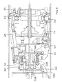
- the pipeline 1 comprises a series of pipes each or which have been welded together to ensure a fluid tight pipeline.
- the internal pipe welding machine 10 enables the joint 6 between the end 4 of pipeline 1 and end 5 of adjacent pipe 3 to be welded from the inside. Additionally the joint 6 can be welded from the outside by the use of a separate external pipe welding machine.
- the internal pipe welding machine 10 comprises the following major components:-
- the nose cone assembly 20 includes a manual welder 19 including a welding torch 21 along with a spool of welding wire 22.
- the nose cone assembly 20 includes a plate 23 to which the thruster assembly 30 is connected.
- the nose cone assembly also includes a plurality of circumferentially equispaced pivotal guide arms 24 (in this case six) which are also connected to the thruster assembly 30.
- Thruster assembly 30 includes a plurality of circumferentially equispaced pipe engaging clamps 31, a pair of guide wheels 32 and a rotatable ring member 33.
- ring member 33 Mounted on ring member 33 is a plurality (in this case six) of circumferentially equispaced automatic welder assemblies 50.
- a plate 61 of articulated joint assembly 60 is attached to the back of the thruster assembly 40. Attached to plate 61 is a plurality (in this case three) or circumferentially equispaced arrester assemblies 40. Each arrester assembly 40 includes an extendable shaft 41 with a positioning abutment 42 at one end.
- the articulated joint assembly 60 allows the front subframe 12 of chassis 11 to articulate relative to the rear subframe 13 of chassis 11 and includes an articulated joint 62 and a plurality (in this case two) of loading wheels 63.
- a plate 71 of the drive assembly 70 is attached to the back of the articulated joint assembly 60.
- Drive assembly 70 includes a plurality (in this case three) or circumferentially equispaced track laying arrangements 72.
- Drive assembly 70 also includes 2 batteries 73 and a tank 74 of inert welding shield gas.
- a plate 75 of the drive assembly 70 is connected to the air receiver assembly 80.
- the air receiver assembly 80 includes an air receiver tank 81.
- command rod rear coupling 85 which is releasably connected to a command rod 86.
- Command rod 86 is of a length such that it projects beyond the end of pipe 3 and includes at that end a command rod control panel (not shown) which can be used to control various functions of the machine and a command rod front coupling (not shown) which releasably connects the command rod to a supply of services eg. compressed air, battery charging current and welding current generators. Control signals pass down the command rod, to the machine, along with service supplies such as compressed air, welding current, and welding shield gas.
- service supplies such as compressed air, welding current, and welding shield gas.
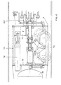
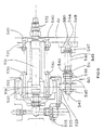
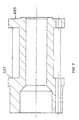
- an articulated joint assembly 60 including a spherical bearing 510 and a plurality (in this case 6) of circumferentially equispaced articulation resisting means 511.
- the spherical bearing 510 includes an outer race 520 and an inner race 521.
- Outer race 520 is mounted in clamp collar 522, plate 523 and housing 524.
- Nuts and bolts 525 secure the clamp collar 522, plate 523 and housing 524 together such that outer race 520 is axially fixed.
- Housing 524 is secured through holes 525 to plate 526 of the rear subframe 13 on the chassis 11.
- Housing 524 includes a manifold 527 having a port 528 connected to air receiver tank 81, a port 529 connected to the actuators of the rear clamp arrangement and a port 530 connected via flexible pipe 531 and rigid pipe 532 to the actuators of the front clamp arrangement.
- Pipe 532 is secured to plate 61 of the front subframe 12 of the chassis 11.
- Bolts 536 secure tube 537 and collar 538 together such that they clamp the inner race 521. End 539 of tube 537 is secured to plate 61 via nut and bolt arrangement 540.
- the spherical bearing 510 allows the front subframe to pitch, yaw and roll relative to the rear subframe whilst services (in this case pressurised air) can be carried between the front and rear subframes through the bearing races 520 and 521.
- the flexible pipe 531 compensates for a relative movement between the front and rear subframes of the chassis 11.
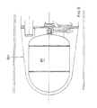
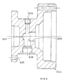
- Each articulation resisting means 511 comprises an axially orientated pin 541 having a threaded portion 542, a plain portion 543 and a conical nose portion 544. Nuts 545 adjustably secure the pin axially relative to plate 523. Mounted on plane portion 543 is a compression spring 546 which acts between collar 547 and washer and nuts arrangement 548. Abutment 549 is secured to plate 61 and includes conical abutment surfacs 550.
- each articulation resisting means is arranged to put their respective springs 546 in to compression to provide a preload which biases the front and rear subframes into alignment.
- Pitch and yaw movement is limited when the conical nose portion 544 of one or more pins 541 contacts the respective conical abutment surface 550 of the abutment 549.
- the spherical bearing 510 also allows roll of the front subframe relative to the rear subframe. However such roll is limited by appropriate contact of one or move conical nose portions 544 with corresponding conical abutment surfaces 550.
- the articulation resisting means 511 therefore not only limit pitch and yaw movement of the front subframe relative to the rear subframe but also limit roll movement of these components relative to each other.
Landscapes
- Physics & Mathematics (AREA)
- Optics & Photonics (AREA)
- Engineering & Computer Science (AREA)
- Mechanical Engineering (AREA)
- Butt Welding And Welding Of Specific Article (AREA)
- Dry Shavers And Clippers (AREA)
- Valve Device For Special Equipments (AREA)
- Reciprocating, Oscillating Or Vibrating Motors (AREA)
- Arc Welding In General (AREA)
- Body Structure For Vehicles (AREA)
- Pressure Welding/Diffusion-Bonding (AREA)
- Extrusion Moulding Of Plastics Or The Like (AREA)
- Iron Core Of Rotating Electric Machines (AREA)
Claims (7)
- Innenrohrschweißmaschine (10) mit einer Montageplatte (11) mit einem vorderen Teilgestell, welches sich in Gelenkverbindung mit einem hinteren Teilgestell befindet, dadurch gekennzeichnet, daß die Gelenkverbindung durch ein Kugelflächenlager (510) mit einem äußeren Laufring (520), welcher entweder an dem vorderen Teilgestell oder dem hinteren Teilgestell befestigt ist, und einem inneren Laufring (521), welcher an dem jeweils anderen Teilgestell aus der Gruppe des vorderen Teilgestells und des hinteren Teilgestells befestigt ist, erfolgt, wobei die Betriebsmittelversorgung zwischen dem vorderen Teilgestell und dem hinteren Teilgestell durch die Kugelflächenlagerlaufringe verläuft.
- Innenrohrschweißmaschine nach Anspruch 1, wobei die Betriebsmittelversorgung die Druckluftversorgung ist.
- Innenrohrschweißmaschine nach Anspruch 1 oder 2, wobei eine Gelenkwiderstandseinrichtung (542, 545, 546, 547, 548) geeignet wirkt, um einer Gelenkbewegung des vorderen Teilgestells gegen das hintere Teilgestell in einer Neige- und einer seitlichen Ablenkrichtung zu widerstehen.
- Innenrohrschweißmaschine nach Anspruch 3, wobei die Gelenkwiderstandseinrichtung ferner die Gelenkbewegung des vorderen Teilgestells gegen das hintere Teilgestell in einer Rollrichtung begrenzt.
- Innenrohrschweißmaschine nach Anspruch 3 oder 4, wobei die Gelenkwiderstandseinrichtung eine Vielzahl im wesentlichen in Axialrichtung ausgerichteter elastischer Einrichtungen (546) umfaßt, welche geeignet zwischen dem vorderen und dem hinteren Teilgestell wirken.
- Innenrohrschweißmaschine nach Anspruch 5, wobei die elastischen Einrichtungen Federn sind, welche auf Zapfen (541) angebracht sind, welche entweder bezüglich des vorderen Teilgestells oder des hinteren Teilgestells befestigt sind.
- Innenrohrschweißmaschine nach Anspruch 6, wobei sich jeder Zapfen in Eingriff mit einem jeweiligen Loch des jeweils anderen Teilgestells aus der Gruppe des vorderen Teilgestells und des hinteren Teilgestells befindet, um die Neigungs-, die seitliche Ablenk- und die Rollbewegung des vorderen Teilgestells gegen das hintere Teilgestell zu begrenzen.
Applications Claiming Priority (3)
| Application Number | Priority Date | Filing Date | Title |
|---|---|---|---|
| GB9900603 | 1999-01-13 | ||
| GB9900603 | 1999-01-13 | ||
| PCT/GB2000/000075 WO2000041842A1 (en) | 1999-01-13 | 2000-01-13 | Welding machine |
Publications (2)
| Publication Number | Publication Date |
|---|---|
| EP1146992A1 EP1146992A1 (de) | 2001-10-24 |
| EP1146992B1 true EP1146992B1 (de) | 2002-12-11 |
Family
ID=10845868
Family Applications (1)
| Application Number | Title | Priority Date | Filing Date |
|---|---|---|---|
| EP00900272A Expired - Lifetime EP1146992B1 (de) | 1999-01-13 | 2000-01-13 | Schweissmaschine |
Country Status (5)
| Country | Link |
|---|---|
| EP (1) | EP1146992B1 (de) |
| AT (1) | ATE229403T1 (de) |
| AU (1) | AU1993500A (de) |
| DE (1) | DE60000968T2 (de) |
| WO (1) | WO2000041842A1 (de) |
Families Citing this family (1)
| Publication number | Priority date | Publication date | Assignee | Title |
|---|---|---|---|---|
| CN106112374B (zh) * | 2016-08-16 | 2017-09-29 | 福建工程学院 | 大型筒形件壳体平焊过程中保持圆度的装置 |
Family Cites Families (4)
| Publication number | Priority date | Publication date | Assignee | Title |
|---|---|---|---|---|
| US3699635A (en) * | 1970-05-26 | 1972-10-24 | Edmund G Bradley | Internal line-up clamp for pipe lines |
| FR2173700A1 (en) * | 1972-02-28 | 1973-10-12 | Travis Valentine | Aligning contiguous pipes - without damaging the interior surface of the pipes |
| US3920171A (en) * | 1974-02-01 | 1975-11-18 | Crc Crose Int Inc | Apparatus for positioning and clamping pipes for welding |
| US4582241A (en) * | 1977-05-25 | 1986-04-15 | Johnson Wallace E | Force transmitting toggle assembly |
-
2000
- 2000-01-13 WO PCT/GB2000/000075 patent/WO2000041842A1/en not_active Ceased
- 2000-01-13 EP EP00900272A patent/EP1146992B1/de not_active Expired - Lifetime
- 2000-01-13 DE DE60000968T patent/DE60000968T2/de not_active Expired - Lifetime
- 2000-01-13 AU AU19935/00A patent/AU1993500A/en not_active Abandoned
- 2000-01-13 AT AT00900272T patent/ATE229403T1/de not_active IP Right Cessation
Also Published As
| Publication number | Publication date |
|---|---|
| AU1993500A (en) | 2000-08-01 |
| DE60000968T2 (de) | 2003-05-28 |
| EP1146992A1 (de) | 2001-10-24 |
| WO2000041842A1 (en) | 2000-07-20 |
| DE60000968D1 (de) | 2003-01-23 |
| ATE229403T1 (de) | 2002-12-15 |
Similar Documents
| Publication | Publication Date | Title |
|---|---|---|
| US5002500A (en) | Quick connect/disconnector for high amperage current | |
| JP3226091B2 (ja) | 配管自動溶接装置 | |
| US3612808A (en) | Shielding gas pressure actuated pipe-welding device | |
| EP1146992B1 (de) | Schweissmaschine | |
| JP3726596B2 (ja) | 遠隔点検検査システムと遠隔保修システム | |
| WO2000041488A2 (en) | Welding machine | |
| WO2000041843A1 (en) | Welding machine | |
| JP2002079487A (ja) | 産業用ロボットの手首装置 | |
| CN110560845B (zh) | 一种远程可视化管道全位置自动氩弧焊接装置 | |
| CN111375978A (zh) | 一种导管环焊缝焊接自动变位装置 | |
| KR101050815B1 (ko) | 지능형 자동용접로봇을 이용한 강관 현장시공 연결방법 | |
| KR100584474B1 (ko) | 자동차 아암 용접용 지그 | |
| CN206047425U (zh) | 一种自动旋转焊接孔洞的装置 | |
| EP1148969B1 (de) | Schweissmaschine | |
| CN116174903B (zh) | 一种激光焊接机器人 | |
| JP2021186839A (ja) | 管材の円周溶接装置 | |
| CN105666001A (zh) | 一种适用于长管法兰的焊接夹具 | |
| CN117549272A (zh) | 一种核辐射环境下的金属管道修复机器人 | |
| CN116604245A (zh) | 一种新型智能机器人焊接设备 | |
| US4945209A (en) | Welding gun swivel | |
| CN221984120U (zh) | 一种焊接装置 | |
| WO2000041490A2 (en) | Welding machine | |
| JPH08267249A (ja) | 溶接機用水冷式トーチ | |
| CN222643630U (zh) | 一种大直径盾构机盾尾分块焊接组装辅助系统 | |
| CN219888996U (zh) | 一种管路快接结构及阀体 |
Legal Events
| Date | Code | Title | Description |
|---|---|---|---|
| PUAI | Public reference made under article 153(3) epc to a published international application that has entered the european phase |
Free format text: ORIGINAL CODE: 0009012 |
|
| 17P | Request for examination filed |
Effective date: 20010810 |
|
| AK | Designated contracting states |
Kind code of ref document: A1 Designated state(s): AT BE CH CY DE DK ES FI FR GB GR IE IT LI LU MC NL PT SE |
|
| GRAG | Despatch of communication of intention to grant |
Free format text: ORIGINAL CODE: EPIDOS AGRA |
|
| 17Q | First examination report despatched |
Effective date: 20020206 |
|
| GRAG | Despatch of communication of intention to grant |
Free format text: ORIGINAL CODE: EPIDOS AGRA |
|
| GRAH | Despatch of communication of intention to grant a patent |
Free format text: ORIGINAL CODE: EPIDOS IGRA |
|
| GRAH | Despatch of communication of intention to grant a patent |
Free format text: ORIGINAL CODE: EPIDOS IGRA |
|
| GRAA | (expected) grant |
Free format text: ORIGINAL CODE: 0009210 |
|
| AK | Designated contracting states |
Kind code of ref document: B1 Designated state(s): AT BE CH CY DE DK ES FI FR GB GR IE IT LI LU MC NL PT SE |
|
| PG25 | Lapsed in a contracting state [announced via postgrant information from national office to epo] |
Ref country code: GR Free format text: LAPSE BECAUSE OF FAILURE TO SUBMIT A TRANSLATION OF THE DESCRIPTION OR TO PAY THE FEE WITHIN THE PRESCRIBED TIME-LIMIT Effective date: 20021211 Ref country code: BE Free format text: LAPSE BECAUSE OF FAILURE TO SUBMIT A TRANSLATION OF THE DESCRIPTION OR TO PAY THE FEE WITHIN THE PRESCRIBED TIME-LIMIT Effective date: 20021211 Ref country code: IT Free format text: LAPSE BECAUSE OF FAILURE TO SUBMIT A TRANSLATION OF THE DESCRIPTION OR TO PAY THE FEE WITHIN THE PRESCRIBED TIME-LIMIT;WARNING: LAPSES OF ITALIAN PATENTS WITH EFFECTIVE DATE BEFORE 2007 MAY HAVE OCCURRED AT ANY TIME BEFORE 2007. THE CORRECT EFFECTIVE DATE MAY BE DIFFERENT FROM THE ONE RECORDED. Effective date: 20021211 Ref country code: LI Free format text: LAPSE BECAUSE OF FAILURE TO SUBMIT A TRANSLATION OF THE DESCRIPTION OR TO PAY THE FEE WITHIN THE PRESCRIBED TIME-LIMIT Effective date: 20021211 Ref country code: FI Free format text: LAPSE BECAUSE OF FAILURE TO SUBMIT A TRANSLATION OF THE DESCRIPTION OR TO PAY THE FEE WITHIN THE PRESCRIBED TIME-LIMIT Effective date: 20021211 Ref country code: FR Free format text: LAPSE BECAUSE OF FAILURE TO SUBMIT A TRANSLATION OF THE DESCRIPTION OR TO PAY THE FEE WITHIN THE PRESCRIBED TIME-LIMIT Effective date: 20021211 Ref country code: CH Free format text: LAPSE BECAUSE OF FAILURE TO SUBMIT A TRANSLATION OF THE DESCRIPTION OR TO PAY THE FEE WITHIN THE PRESCRIBED TIME-LIMIT Effective date: 20021211 Ref country code: NL Free format text: LAPSE BECAUSE OF FAILURE TO SUBMIT A TRANSLATION OF THE DESCRIPTION OR TO PAY THE FEE WITHIN THE PRESCRIBED TIME-LIMIT Effective date: 20021211 Ref country code: AT Free format text: LAPSE BECAUSE OF FAILURE TO SUBMIT A TRANSLATION OF THE DESCRIPTION OR TO PAY THE FEE WITHIN THE PRESCRIBED TIME-LIMIT Effective date: 20021211 |
|
| REF | Corresponds to: |
Ref document number: 229403 Country of ref document: AT Date of ref document: 20021215 Kind code of ref document: T |
|
| REG | Reference to a national code |
Ref country code: GB Ref legal event code: FG4D |
|
| REG | Reference to a national code |
Ref country code: CH Ref legal event code: EP |
|
| PG25 | Lapsed in a contracting state [announced via postgrant information from national office to epo] |
Ref country code: IE Free format text: LAPSE BECAUSE OF NON-PAYMENT OF DUE FEES Effective date: 20030113 Ref country code: LU Free format text: LAPSE BECAUSE OF NON-PAYMENT OF DUE FEES Effective date: 20030113 Ref country code: CY Free format text: LAPSE BECAUSE OF FAILURE TO SUBMIT A TRANSLATION OF THE DESCRIPTION OR TO PAY THE FEE WITHIN THE PRESCRIBED TIME-LIMIT Effective date: 20030113 |
|
| REG | Reference to a national code |
Ref country code: IE Ref legal event code: FG4D |
|
| REF | Corresponds to: |
Ref document number: 60000968 Country of ref document: DE Date of ref document: 20030123 |
|
| PG25 | Lapsed in a contracting state [announced via postgrant information from national office to epo] |
Ref country code: MC Free format text: LAPSE BECAUSE OF NON-PAYMENT OF DUE FEES Effective date: 20030131 |
|
| PG25 | Lapsed in a contracting state [announced via postgrant information from national office to epo] |
Ref country code: PT Free format text: LAPSE BECAUSE OF FAILURE TO SUBMIT A TRANSLATION OF THE DESCRIPTION OR TO PAY THE FEE WITHIN THE PRESCRIBED TIME-LIMIT Effective date: 20030311 Ref country code: DK Free format text: LAPSE BECAUSE OF FAILURE TO SUBMIT A TRANSLATION OF THE DESCRIPTION OR TO PAY THE FEE WITHIN THE PRESCRIBED TIME-LIMIT Effective date: 20030311 Ref country code: SE Free format text: LAPSE BECAUSE OF FAILURE TO SUBMIT A TRANSLATION OF THE DESCRIPTION OR TO PAY THE FEE WITHIN THE PRESCRIBED TIME-LIMIT Effective date: 20030311 |
|
| NLV1 | Nl: lapsed or annulled due to failure to fulfill the requirements of art. 29p and 29m of the patents act | ||
| PG25 | Lapsed in a contracting state [announced via postgrant information from national office to epo] |
Ref country code: ES Free format text: LAPSE BECAUSE OF FAILURE TO SUBMIT A TRANSLATION OF THE DESCRIPTION OR TO PAY THE FEE WITHIN THE PRESCRIBED TIME-LIMIT Effective date: 20030627 |
|
| REG | Reference to a national code |
Ref country code: CH Ref legal event code: PL |
|
| PLBE | No opposition filed within time limit |
Free format text: ORIGINAL CODE: 0009261 |
|
| STAA | Information on the status of an ep patent application or granted ep patent |
Free format text: STATUS: NO OPPOSITION FILED WITHIN TIME LIMIT |
|
| EN | Fr: translation not filed | ||
| REG | Reference to a national code |
Ref country code: IE Ref legal event code: MM4A |
|
| 26N | No opposition filed |
Effective date: 20030912 |
|
| REG | Reference to a national code |
Ref country code: GB Ref legal event code: 732E |
|
| REG | Reference to a national code |
Ref country code: GB Ref legal event code: 732E Free format text: REGISTERED BETWEEN 20100204 AND 20100211 |
|
| PGFP | Annual fee paid to national office [announced via postgrant information from national office to epo] |
Ref country code: GB Payment date: 20101210 Year of fee payment: 12 |
|
| PGFP | Annual fee paid to national office [announced via postgrant information from national office to epo] |
Ref country code: DE Payment date: 20110315 Year of fee payment: 12 |
|
| GBPC | Gb: european patent ceased through non-payment of renewal fee |
Effective date: 20120113 |
|
| PG25 | Lapsed in a contracting state [announced via postgrant information from national office to epo] |
Ref country code: GB Free format text: LAPSE BECAUSE OF NON-PAYMENT OF DUE FEES Effective date: 20120113 Ref country code: DE Free format text: LAPSE BECAUSE OF NON-PAYMENT OF DUE FEES Effective date: 20120801 |
|
| REG | Reference to a national code |
Ref country code: DE Ref legal event code: R119 Ref document number: 60000968 Country of ref document: DE Effective date: 20120801 |