EP1146289A1 - Cooling structure of combustor tail tube - Google Patents
Cooling structure of combustor tail tube Download PDFInfo
- Publication number
- EP1146289A1 EP1146289A1 EP01108310A EP01108310A EP1146289A1 EP 1146289 A1 EP1146289 A1 EP 1146289A1 EP 01108310 A EP01108310 A EP 01108310A EP 01108310 A EP01108310 A EP 01108310A EP 1146289 A1 EP1146289 A1 EP 1146289A1
- Authority
- EP
- European Patent Office
- Prior art keywords
- tail tube
- cooling
- wall
- combustor
- outlet
- Prior art date
- Legal status (The legal status is an assumption and is not a legal conclusion. Google has not performed a legal analysis and makes no representation as to the accuracy of the status listed.)
- Granted
Links
Images


Classifications
-
- F—MECHANICAL ENGINEERING; LIGHTING; HEATING; WEAPONS; BLASTING
- F23—COMBUSTION APPARATUS; COMBUSTION PROCESSES
- F23M—CASINGS, LININGS, WALLS OR DOORS SPECIALLY ADAPTED FOR COMBUSTION CHAMBERS, e.g. FIREBRIDGES; DEVICES FOR DEFLECTING AIR, FLAMES OR COMBUSTION PRODUCTS IN COMBUSTION CHAMBERS; SAFETY ARRANGEMENTS SPECIALLY ADAPTED FOR COMBUSTION APPARATUS; DETAILS OF COMBUSTION CHAMBERS, NOT OTHERWISE PROVIDED FOR
- F23M5/00—Casings; Linings; Walls
- F23M5/08—Cooling thereof; Tube walls
-
- F—MECHANICAL ENGINEERING; LIGHTING; HEATING; WEAPONS; BLASTING
- F01—MACHINES OR ENGINES IN GENERAL; ENGINE PLANTS IN GENERAL; STEAM ENGINES
- F01D—NON-POSITIVE DISPLACEMENT MACHINES OR ENGINES, e.g. STEAM TURBINES
- F01D9/00—Stators
- F01D9/02—Nozzles; Nozzle boxes; Stator blades; Guide conduits, e.g. individual nozzles
- F01D9/023—Transition ducts between combustor cans and first stage of the turbine in gas-turbine engines; their cooling or sealings
-
- F—MECHANICAL ENGINEERING; LIGHTING; HEATING; WEAPONS; BLASTING
- F02—COMBUSTION ENGINES; HOT-GAS OR COMBUSTION-PRODUCT ENGINE PLANTS
- F02C—GAS-TURBINE PLANTS; AIR INTAKES FOR JET-PROPULSION PLANTS; CONTROLLING FUEL SUPPLY IN AIR-BREATHING JET-PROPULSION PLANTS
- F02C7/00—Features, components parts, details or accessories, not provided for in, or of interest apart form groups F02C1/00 - F02C6/00; Air intakes for jet-propulsion plants
- F02C7/12—Cooling of plants
- F02C7/16—Cooling of plants characterised by cooling medium
-
- F—MECHANICAL ENGINEERING; LIGHTING; HEATING; WEAPONS; BLASTING
- F23—COMBUSTION APPARATUS; COMBUSTION PROCESSES
- F23R—GENERATING COMBUSTION PRODUCTS OF HIGH PRESSURE OR HIGH VELOCITY, e.g. GAS-TURBINE COMBUSTION CHAMBERS
- F23R3/00—Continuous combustion chambers using liquid or gaseous fuel
- F23R3/002—Wall structures
-
- F—MECHANICAL ENGINEERING; LIGHTING; HEATING; WEAPONS; BLASTING
- F05—INDEXING SCHEMES RELATING TO ENGINES OR PUMPS IN VARIOUS SUBCLASSES OF CLASSES F01-F04
- F05D—INDEXING SCHEME FOR ASPECTS RELATING TO NON-POSITIVE-DISPLACEMENT MACHINES OR ENGINES, GAS-TURBINES OR JET-PROPULSION PLANTS
- F05D2260/00—Function
- F05D2260/20—Heat transfer, e.g. cooling
- F05D2260/232—Heat transfer, e.g. cooling characterized by the cooling medium
- F05D2260/2322—Heat transfer, e.g. cooling characterized by the cooling medium steam
Definitions
- the present invention relates to a cooling structure of a combustor tail tube for gas turbine.
- Such steam cooling is employed in cooling of, for example as shown in Fig. 9, a tail tube 4 of a multi-nozzle type premixed combustor 3 having premixed flame forming nozzles 2 for forming and injecting a premixed gas of main fuel and combustion air, divided and disposed in plural positions around a cone 1 for forming a diffusion flame by reaction between pilot fuel and combustion air.
- the cooling steam is first supplied into the middle part of the tail tube 4 in the longitudinal direction (see manifold 6b) from the cooling jackets 5 (see Fig. 10) and manifolds 6a, 6b, 6c formed inside the wall of the tail tube 4, and is divided into the upstream side and downstream side of gas flow indicated by arrow in the diagram to cool the wall surface, and is collected from the inlet (see manifold 6a) and outlet (see manifold 6c) of the tail tube 4.
- a reverse flow of cooling steam is also known, that is, the cooling steam is first supplied from the inlet (see manifold 6a) and outlet (see manifold 6c) of the tail tube 4, and then flows into the middle part (see manifold 6b) to cool the wall surface, and is collected from the middle part.
- the cooling jacket 5 is formed, as shown in Fig. 10, by processing a groove (see groove processing part "a") in width D 1 and depth D 2 in one wall 4a of the tail tube 4 of double wall structure, and brazing the groove side to other wall 4b (see brazing part "b").
- the temperature condition generally differs locally in the elevated position of metal temperature at the inner side (rotor side) and lateral side (opposite sides of adjacent tail tubes) from the outer side (casing side) of the tail tube 4 formed in a rectangular shape at the outlet side
- the size (passage sectional area) of the cooling jackets 5 is set uniformly on the entire circumference, and the flow rate distribution of cooling steam to necessary parts is set regardless of the metal temperature, and cracks are likely to be formed at four corners of the outlet of the tail tube 4 due to thermal deformation caused by increase of thermal stress by uneven metal temperature and lack of cooling in the outlet (in particular, flange) of the tail tube 4.
- the invention is devised in the light of the above background, and it is hence an object thereof to present a cooling structure of combustor tail tube capable of preventing formation of tail tube cracks by decreasing the thermal stress and preventing thermal deformation, and extending the service life.
- the invention presents a cooling structure of combustor tail tube forming a multiplicity of cooling jackets extending in the longitudinal direction of tail tube of a gas turbine combustor along the entire circumference of the tail tube wall, in which passage sectional area of the cooling jackets is varied depending on the metal temperature of the tail tube parts.
- the passage sectional area of the cooling jackets formed at the rotor side wall and the mutually opposite side walls of the adjacent tail tube is formed larger than the passage sectional area of the cooling jackets formed at the casing side wall of the tail tube.
- the cooling jackets are extended from the root of the flange attached to the peripheral edge of the outlet of the tail tube in the flange height direction, and are pulled back after the cooling medium is supplied in the area.
- an annular cooling passage is formed to surround the outlet in the front portion of the flange attached to the edge of the outlet of the tail tube, and the cooling medium is directly supplied into the cooling passage without cooling the tail tube wall.
- the tail tube is formed n a double wall structure, a groove is processed in one wall, the groove side is bonded with the other wall to form a cooling jacket, and the groove side wall is disposed at the inner wall side to be exposed to combustion gas.
- the cooling medium is supplied from the combustion gas outlet of the tail tube, and the cooling medium is collected from one position at the combustion gas inlet side.
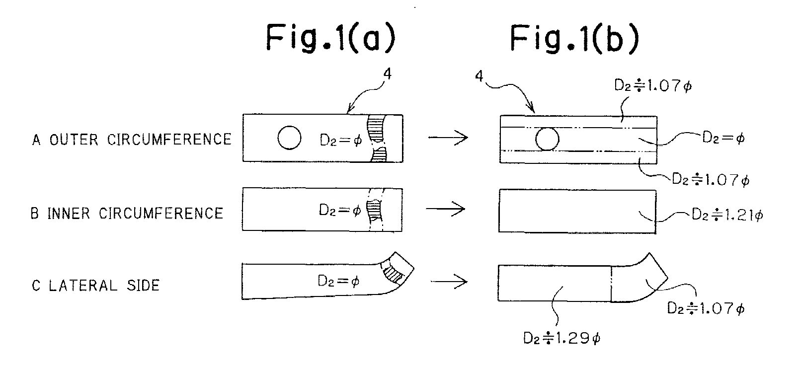
- Fig. 1 is a structural explanatory diagram of a cooling jacket showing a first embodiment of the invention, in which (a) is an explanatory diagram of size of an existing cooling jacket, (b) is an explanatory diagram of size of the cooling jacket of the invention, and (c) is a partial cut-away perspective view of a tail tube. Also in (a), the passage of cooling jacket is shown in a partially cut-away view.
- the cooling jacket (see reference numeral 5 in Fig. 10) formed inside the wall of the tail tube 4 formed in a rectangular shape at the outlet side is expanded in its passage sectional area in most parts as compared with the existing cooling jacket, and further the passage sectional area is varied, for example, in the outer circumference (casing side) A of the tail tube 4, inner circumference (rotor side) b, and lateral side (opposite sides of adjacent tail tubes) C, depending on the metal temperature of the parts of the tail tube 4.
- the number of cooling jackets is same in both the existing structure and the embodiment.
- the cooling jacket size of the parts so that the metal temperature may be uniform in the parts of the tail tube 4
- the flow rate distribution of cooling steam as cooling medium is optimized, and therefore thermal deformation due to increase of thermal stress by uneven metal temperature and lack of cooling of outlet of the tail tube 4 can be effectively prevented, and crack formation at the outlet of the tail tube 4 can be avoided.
- the groove width D 1 may be also increased, together with the groove depth D 2 , to change the cooling jacket size in various parts.
- Fig. 2 is a structural explanatory diagram of a tail tube outlet showing a second embodiment of the invention, in which (a) is a structural explanatory diagram of an existing tail tube outlet, and (b) is a structural explanatory diagram of a tail tube outlet of the invention.
- the entire structure of the tail tube is shown in Fig. 9, and detailed description is omitted herein.
- the destination of the cooling jacket 5 (see Fig. 10) for supplying cooling steam to the flange 4a projecting outward to the outlet peripheral edge (opening peripheral edge) of the tail tube 4 is changed, so that the flange 4a is cooled by steam in particular.
- the cooling steam sent to the root of the flange 4a flows into the adjacent cooling jacket 5 at the root, and slightly returns to the upstream side, and flows into the manifold 6c through the pass hole 5a (formed at every other cooling jacket 5), whereas, in the embodiment, as shown in Fig. 2 (b), the cooling steam sent into the root of the flange 4a flows through the passage 5b extended in the height direction of the flange 4a, and flows into the manifold 6c. Therefore, the passage 5b is, unlike the pass hole 5a, is formed in every cooling jacket 5.
- the cooling steam is supplied into the entire flange 4a at the outlet of the tail tube 4, and cooling of the flange 4a is reinforced, so that thermal deformation due to temperature difference can be prevented, and crack formation at the outlet of the tail tube 4 can be avoided.
- Fig. 3 is an essential side view of a tail tube showing a third embodiment of the invention
- Fig. 4 is a back perspective view of the tail tube outlet
- Fig. 5 is a front view of the tail tube outlet
- Fig. 6 is a sectional view of VI-VI in Fig. 5.
- bypass steam jackets 10a to 10d are formed, and the cooling steam not cooling the wall of the tail tube 4 is supplied through the bypass steam jackets 10a to 10d into an annular cooling passage 11 formed at the front side of the flange 4a at the outlet of the tail tube 4, so that the flange 4a is cooled by steam in particular.
- bypass steam jackets 10a to 10d are branched into four lines in the peripheral direction along the outer circumference of the tail tube 4 from the manifold 6b, and communicate with steam sumps 12a to 12d formed at four corners at the outlet of the tail tube 4.
- the steam sumps 12a to 12d communicate with the cooling passage 11 through pass holes 13a to 13d and groove passages 14a to 14d formed at four corners of the rectangular flange 4a.
- the cooling steam is guided into the manifold 6c through tiny hole groups 15a to 15d formed at four peripheral positions, and it is mixed with the cooling steam from the cooling jackets 5 herein, and collected.
- Reference numeral 16 in the drawing is a cover plate for closing the cooling passage 11 and groove passages 14a to 14d after processing the grooves.
- the flange 4a at the outlet of the tail tube 4 is cooled entirely by the steam by the cooling steam at low temperature supplied into the annular cooling passage 11 without heat exchange from the manifold 6b by way of the bypass steam jackets 10a to 10d, steam sumps 12a to 12d, pass holes 13a to 13d, and groove passages 14a to 14d, and a sufficient cooling effect is obtained, and thermal deformation due to temperature difference is prevented, and formation of cracks at the outlet of the tail tube 4 is avoided.
- Fig. 7 is a side sectional view of a gas turbine combustor showing a fourth embodiment of the invention
- Fig. 8 is a sectional view of VIII-VIII in Fig. 7.
- same reference numerals are given to the parts and members same as in Fig. 9 and Fig. 10, and detailed description is omitted.
- the invention is applied to steam cooling of a tail tube 4 of a multi-nozzle type premixed combustor 3 having premixed flame forming nozzles 2 for forming and injecting a premixed gas of main fuel and combustion air, divided and disposed in plural positions around a cone 1 for forming a diffusion flame by reaction between pilot fuel and combustion air.
- the cooling steam is first supplied into the outlet (see manifold 6c) of the tail tube 4 from the cooling jackets 5A (see Fig. 8) and manifolds 6a, 6c formed in the wall of the tail tube 4, and flows in the upstream side of the gas flow as indicated by arrow to cool the wall surface, and is collected from one position at the inlet (see manifold 6a) of the tail tube 4.
- the cooling jacket 5A is formed, as shown in Fig. 8, by processing a groove (see groove processing part "a") in D 1 ⁇ D 2 in one wall 4a of the tail tube 4 of double wall structure, and brazing the groove side to other wall 4b (see brazing part “b"), and the groove side wall 4a is disposed at the inner wall side to be exposed to the combustion gas.
- the other wall 4b at the outer wall side is formed slightly thicker than in the prior art in consideration of the strength in the bending process.
- the wall 4a is also considerably thicker than in the prior art in order to prevent lowering of strength in the brazing part "b" by equalizing the itch of the cooling jackets 5A, and to increase the passage sectional area by increasing the groove depth D 2 .
- the brazing part "b" of the cooling jacket 5A can be set apart from the combustion gas as far as possible, so that temperature elevation due to combustion gas can be prevented.
- steam cooling is executed in one pass from the outlet to the inlet of the tail tube 4, so that the outlet of the tail tube can be cooled by the steam (or air in the invention) before temperature elevation by heat exchange.
- the metal temperature is lowered, low cycle fatigue life is extended, and formation of cracks at four corners of the outlet of the tail tube 4 due to elevation of thermal stress as in prior art can be avoided.
- the groove depth D 2 and increasing the passage sectional area lowering of strength of brazing part "b" can be prevented while the same steam flow rate is maintained.
- the number of jackets and manifolds can be decreased, and the structure may be simplified.
- the invention is not limited to these illustrated embodiments alone, but it must be noted that the invention may be changed or modified within the scope not departing from the true spirit thereof by, for example, using air as cooling medium, or executing the first to fourth embodiments simultaneously. Still more, the cooling jacket structure as shown in Fig. 8 may be applied to the steam cooling of two-position collection system as shown in Fig. 9.
- the passage sectional area of the cooling jackets is varied depending on the metal temperature of the tail tube parts, and therefore the flow rate distribution of cooling medium is optimized, and thermal deformation due to increase of thermal stress by uneven metal temperature and lack of cooling at the tail tube outlet can be effectively prevented, and crack formation at the outlet of the tail tube can be avoided.
Landscapes
- Engineering & Computer Science (AREA)
- Chemical & Material Sciences (AREA)
- Combustion & Propulsion (AREA)
- Mechanical Engineering (AREA)
- General Engineering & Computer Science (AREA)
- Turbine Rotor Nozzle Sealing (AREA)
Abstract
Description
Claims (6)
- A cooling structure of combustor tail tube forming a multiplicity of cooling jackets extending in the longitudinal direction of tail tube of a gas turbine combustor along the entire circumference of the tail tube wall, wherein passage sectional area of the cooling jackets is varied depending on the metal temperature of the tail tube parts.
- The cooling structure of combustor tail tube of claim 1, wherein the passage sectional area of the cooling jackets formed at the rotor side wall and the mutually opposite side walls of the adjacent tail tube is formed larger than the passage sectional area of the cooling jackets formed at the casing side wall of the tail tube.
- The cooling structure of combustor tail tube of claim 1, wherein the cooling jackets are extended from the root of the flange attached to the peripheral edge of the outlet of the tail tube in the flange height direction, and are pulled back after the cooling medium is supplied in the area.
- The cooling structure of combustor tail tube of claim 1, wherein an annular cooling passage is formed to surround the outlet in the front portion of the flange attached to the edge of the outlet of the tail tube, and the cooling medium is directly supplied into the cooling passage without cooling the tail tube wall.
- The cooling structure of combustor tail tube of claim 1, wherein the tail tube is formed n a double wall structure, a groove is processed in one wall, the groove side is bonded with the other wall to form a cooling jacket, and the groove side wall is disposed at the inner wall side to be exposed to combustion gas.
- The cooling structure of combustor tail tube of claim 1, wherein the cooling medium is supplied from the combustion gas outlet of the tail tube, and the cooling medium is collected from one position at the combustion gas inlet side.
Applications Claiming Priority (6)
| Application Number | Priority Date | Filing Date | Title |
|---|---|---|---|
| JP2000111557 | 2000-04-13 | ||
| JP2000111557A JP2001295668A (en) | 2000-04-13 | 2000-04-13 | Combustor wall cooling system |
| JP2000152426A JP4240759B2 (en) | 2000-05-24 | 2000-05-24 | Combustor tail cooling structure |
| JP2000152426 | 2000-05-24 | ||
| JP2000184225A JP2002004884A (en) | 2000-06-20 | 2000-06-20 | Cooling structure for combustor wall |
| JP2000184225 | 2000-06-20 |
Publications (2)
| Publication Number | Publication Date |
|---|---|
| EP1146289A1 true EP1146289A1 (en) | 2001-10-17 |
| EP1146289B1 EP1146289B1 (en) | 2008-12-24 |
Family
ID=27343076
Family Applications (1)
| Application Number | Title | Priority Date | Filing Date |
|---|---|---|---|
| EP01108310A Expired - Lifetime EP1146289B1 (en) | 2000-04-13 | 2001-04-02 | Cooling structure of combustor tail tube |
Country Status (4)
| Country | Link |
|---|---|
| US (1) | US6553766B2 (en) |
| EP (1) | EP1146289B1 (en) |
| CA (1) | CA2344012C (en) |
| DE (1) | DE60137099D1 (en) |
Cited By (9)
| Publication number | Priority date | Publication date | Assignee | Title |
|---|---|---|---|---|
| EP1170464A2 (en) * | 2000-07-04 | 2002-01-09 | MAN Turbomaschinen AG GHH BORSIG | Cooling device for an element with an unequal thermal charge |
| EP1239117A2 (en) * | 2001-02-16 | 2002-09-11 | Mitsubishi Heavy Industries, Ltd. | Gas turbine combustor transition piece outlet structure, transition piece, combustor and gas turbine |
| US11255545B1 (en) | 2020-10-26 | 2022-02-22 | General Electric Company | Integrated combustion nozzle having a unified head end |
| US11371702B2 (en) | 2020-08-31 | 2022-06-28 | General Electric Company | Impingement panel for a turbomachine |
| US11460191B2 (en) | 2020-08-31 | 2022-10-04 | General Electric Company | Cooling insert for a turbomachine |
| US11614233B2 (en) | 2020-08-31 | 2023-03-28 | General Electric Company | Impingement panel support structure and method of manufacture |
| US11767766B1 (en) | 2022-07-29 | 2023-09-26 | General Electric Company | Turbomachine airfoil having impingement cooling passages |
| US11994293B2 (en) | 2020-08-31 | 2024-05-28 | General Electric Company | Impingement cooling apparatus support structure and method of manufacture |
| US11994292B2 (en) | 2020-08-31 | 2024-05-28 | General Electric Company | Impingement cooling apparatus for turbomachine |
Families Citing this family (13)
| Publication number | Priority date | Publication date | Assignee | Title |
|---|---|---|---|---|
| JP2002317650A (en) * | 2001-04-24 | 2002-10-31 | Mitsubishi Heavy Ind Ltd | Gas turbine combustor |
| US7178341B2 (en) * | 2004-06-17 | 2007-02-20 | Siemens Power Generation, Inc. | Multi-zone tubing assembly for a transition piece of a gas turbine |
| US8245515B2 (en) | 2008-08-06 | 2012-08-21 | General Electric Company | Transition duct aft end frame cooling and related method |
| US8033119B2 (en) * | 2008-09-25 | 2011-10-11 | Siemens Energy, Inc. | Gas turbine transition duct |
| US8549861B2 (en) * | 2009-01-07 | 2013-10-08 | General Electric Company | Method and apparatus to enhance transition duct cooling in a gas turbine engine |
| JP5260402B2 (en) * | 2009-04-30 | 2013-08-14 | 三菱重工業株式会社 | Plate-like body manufacturing method, plate-like body, gas turbine combustor, and gas turbine |
| US9255484B2 (en) * | 2011-03-16 | 2016-02-09 | General Electric Company | Aft frame and method for cooling aft frame |
| CN103649468A (en) * | 2011-03-31 | 2014-03-19 | 通用电气公司 | Power augmentation system with dynamics damping |
| JP5804872B2 (en) * | 2011-09-27 | 2015-11-04 | 三菱日立パワーシステムズ株式会社 | Combustor transition piece, gas turbine equipped with the same, and transition piece manufacturing method |
| US9574498B2 (en) * | 2013-09-25 | 2017-02-21 | General Electric Company | Internally cooled transition duct aft frame with serpentine cooling passage and conduit |
| US10718224B2 (en) * | 2017-10-13 | 2020-07-21 | General Electric Company | AFT frame assembly for gas turbine transition piece |
| US10684016B2 (en) * | 2017-10-13 | 2020-06-16 | General Electric Company | Aft frame assembly for gas turbine transition piece |
| US20240309814A1 (en) * | 2023-03-13 | 2024-09-19 | Raytheon Technologies Corporation | Selective steam distribution to steam cooled zones in a turbine engine |
Citations (7)
| Publication number | Priority date | Publication date | Assignee | Title |
|---|---|---|---|---|
| EP0203431A1 (en) * | 1985-05-14 | 1986-12-03 | General Electric Company | Impingement cooled transition duct |
| US4719748A (en) * | 1985-05-14 | 1988-01-19 | General Electric Company | Impingement cooled transition duct |
| EP0725253A2 (en) * | 1995-02-01 | 1996-08-07 | Mitsubishi Jukogyo Kabushiki Kaisha | Gas turbine combustor |
| EP0815995A2 (en) * | 1996-06-24 | 1998-01-07 | General Electric Company | Method for making cylindrical structures with cooling channels |
| US5906093A (en) * | 1997-02-21 | 1999-05-25 | Siemens Westinghouse Power Corporation | Gas turbine combustor transition |
| EP0972992A2 (en) * | 1998-07-16 | 2000-01-19 | General Electric Company | Combustor liner |
| US6018950A (en) * | 1997-06-13 | 2000-02-01 | Siemens Westinghouse Power Corporation | Combustion turbine modular cooling panel |
Family Cites Families (7)
| Publication number | Priority date | Publication date | Assignee | Title |
|---|---|---|---|---|
| US3572031A (en) * | 1969-07-11 | 1971-03-23 | United Aircraft Corp | Variable area cooling passages for gas turbine burners |
| JP2984427B2 (en) | 1991-08-13 | 1999-11-29 | 三菱重工業株式会社 | Cooling method of gas turbine high temperature part |
| DE4443864A1 (en) * | 1994-12-09 | 1996-06-13 | Abb Management Ag | Cooled wall part |
| US5724816A (en) * | 1996-04-10 | 1998-03-10 | General Electric Company | Combustor for a gas turbine with cooling structure |
| JP3310900B2 (en) * | 1997-04-15 | 2002-08-05 | 三菱重工業株式会社 | Cooling structure of combustor transition piece |
| CA2288557C (en) * | 1998-11-12 | 2007-02-06 | Mitsubishi Heavy Industries, Ltd. | Gas turbine combustor cooling structure |
| JP3626861B2 (en) | 1998-11-12 | 2005-03-09 | 三菱重工業株式会社 | Gas turbine combustor cooling structure |
-
2001
- 2001-04-02 EP EP01108310A patent/EP1146289B1/en not_active Expired - Lifetime
- 2001-04-02 DE DE60137099T patent/DE60137099D1/en not_active Expired - Lifetime
- 2001-04-12 US US09/832,937 patent/US6553766B2/en not_active Expired - Lifetime
- 2001-04-12 CA CA002344012A patent/CA2344012C/en not_active Expired - Fee Related
Patent Citations (7)
| Publication number | Priority date | Publication date | Assignee | Title |
|---|---|---|---|---|
| EP0203431A1 (en) * | 1985-05-14 | 1986-12-03 | General Electric Company | Impingement cooled transition duct |
| US4719748A (en) * | 1985-05-14 | 1988-01-19 | General Electric Company | Impingement cooled transition duct |
| EP0725253A2 (en) * | 1995-02-01 | 1996-08-07 | Mitsubishi Jukogyo Kabushiki Kaisha | Gas turbine combustor |
| EP0815995A2 (en) * | 1996-06-24 | 1998-01-07 | General Electric Company | Method for making cylindrical structures with cooling channels |
| US5906093A (en) * | 1997-02-21 | 1999-05-25 | Siemens Westinghouse Power Corporation | Gas turbine combustor transition |
| US6018950A (en) * | 1997-06-13 | 2000-02-01 | Siemens Westinghouse Power Corporation | Combustion turbine modular cooling panel |
| EP0972992A2 (en) * | 1998-07-16 | 2000-01-19 | General Electric Company | Combustor liner |
Cited By (12)
| Publication number | Priority date | Publication date | Assignee | Title |
|---|---|---|---|---|
| EP1170464A2 (en) * | 2000-07-04 | 2002-01-09 | MAN Turbomaschinen AG GHH BORSIG | Cooling device for an element with an unequal thermal charge |
| EP1170464A3 (en) * | 2000-07-04 | 2003-07-02 | MAN Turbomaschinen AG | Cooling device for an element with an unequal thermal charge |
| EP1239117A2 (en) * | 2001-02-16 | 2002-09-11 | Mitsubishi Heavy Industries, Ltd. | Gas turbine combustor transition piece outlet structure, transition piece, combustor and gas turbine |
| EP1239117A3 (en) * | 2001-02-16 | 2004-01-14 | Mitsubishi Heavy Industries, Ltd. | Gas turbine combustor transition piece outlet structure, transition piece, combustor and gas turbine |
| US6769257B2 (en) | 2001-02-16 | 2004-08-03 | Mitsubishi Heavy Industries, Ltd. | Transition piece outlet structure enabling to reduce the temperature, and a transition piece, a combustor and a gas turbine providing the above output structure |
| US11371702B2 (en) | 2020-08-31 | 2022-06-28 | General Electric Company | Impingement panel for a turbomachine |
| US11460191B2 (en) | 2020-08-31 | 2022-10-04 | General Electric Company | Cooling insert for a turbomachine |
| US11614233B2 (en) | 2020-08-31 | 2023-03-28 | General Electric Company | Impingement panel support structure and method of manufacture |
| US11994293B2 (en) | 2020-08-31 | 2024-05-28 | General Electric Company | Impingement cooling apparatus support structure and method of manufacture |
| US11994292B2 (en) | 2020-08-31 | 2024-05-28 | General Electric Company | Impingement cooling apparatus for turbomachine |
| US11255545B1 (en) | 2020-10-26 | 2022-02-22 | General Electric Company | Integrated combustion nozzle having a unified head end |
| US11767766B1 (en) | 2022-07-29 | 2023-09-26 | General Electric Company | Turbomachine airfoil having impingement cooling passages |
Also Published As
| Publication number | Publication date |
|---|---|
| EP1146289B1 (en) | 2008-12-24 |
| DE60137099D1 (en) | 2009-02-05 |
| US6553766B2 (en) | 2003-04-29 |
| CA2344012A1 (en) | 2001-10-13 |
| CA2344012C (en) | 2005-08-30 |
| US20010037646A1 (en) | 2001-11-08 |
Similar Documents
| Publication | Publication Date | Title |
|---|---|---|
| EP1146289A1 (en) | Cooling structure of combustor tail tube | |
| US6170266B1 (en) | Combustion apparatus | |
| EP0516322B1 (en) | Shroud cooling assembly for gas turbine engine | |
| US6282905B1 (en) | Gas turbine combustor cooling structure | |
| CA2333936C (en) | Film cooling strip for gas turbine engine combustion chamber | |
| EP0911486B1 (en) | Gas turbine stationary blade cooling | |
| US6000908A (en) | Cooling for double-wall structures | |
| EP0284819B1 (en) | Gas turbine combustor transition duct forced convection cooling | |
| US8166764B2 (en) | Flow sleeve impingement cooling using a plenum ring | |
| US7493767B2 (en) | Method and apparatus for cooling combustor liner and transition piece of a gas turbine | |
| US6340285B1 (en) | End rail cooling for combined high and low pressure turbine shroud | |
| US7886541B2 (en) | Wall elements for gas turbine engine combustors | |
| US6779597B2 (en) | Multiple impingement cooled structure | |
| US6708499B2 (en) | Combustion apparatus | |
| US5207556A (en) | Airfoil having multi-passage baffle | |
| US7574865B2 (en) | Combustor flow sleeve with optimized cooling and airflow distribution | |
| EP1143107A2 (en) | Gas turbine transition duct end frame cooling | |
| JP2003027902A (en) | Stator blade of gas turbine | |
| JP2009085222A (en) | Rear end liner assembly with turbulator and its cooling method | |
| CA2598506A1 (en) | Cooled transition duct for a gas turbine engine | |
| US20050047907A1 (en) | Transition duct cooling system | |
| CN113719862B (en) | Split double-wall small bent pipe of reflux combustion chamber and lap joint structure of same and flame tube | |
| US8522557B2 (en) | Cooling channel for cooling a hot gas guiding component | |
| JPH06221562A (en) | Combustor of gas turbine | |
| CN115434756A (en) | Double-wall cooling structure of turbine blade |
Legal Events
| Date | Code | Title | Description |
|---|---|---|---|
| PUAI | Public reference made under article 153(3) epc to a published international application that has entered the european phase |
Free format text: ORIGINAL CODE: 0009012 |
|
| 17P | Request for examination filed |
Effective date: 20010402 |
|
| AK | Designated contracting states |
Kind code of ref document: A1 Designated state(s): CH DE FR GB IT LI Kind code of ref document: A1 Designated state(s): AT BE CH CY DE DK ES FI FR GB GR IE IT LI LU MC NL PT SE TR |
|
| AX | Request for extension of the european patent |
Free format text: AL;LT;LV;MK;RO;SI |
|
| AKX | Designation fees paid |
Free format text: CH DE FR GB IT LI |
|
| 17Q | First examination report despatched |
Effective date: 20060816 |
|
| GRAP | Despatch of communication of intention to grant a patent |
Free format text: ORIGINAL CODE: EPIDOSNIGR1 |
|
| GRAS | Grant fee paid |
Free format text: ORIGINAL CODE: EPIDOSNIGR3 |
|
| GRAA | (expected) grant |
Free format text: ORIGINAL CODE: 0009210 |
|
| AK | Designated contracting states |
Kind code of ref document: B1 Designated state(s): CH DE FR GB IT LI |
|
| REG | Reference to a national code |
Ref country code: GB Ref legal event code: FG4D |
|
| REG | Reference to a national code |
Ref country code: CH Ref legal event code: EP Ref country code: CH Ref legal event code: NV Representative=s name: E. BLUM & CO. AG PATENT- UND MARKENANWAELTE VSP |
|
| REF | Corresponds to: |
Ref document number: 60137099 Country of ref document: DE Date of ref document: 20090205 Kind code of ref document: P |
|
| PLBE | No opposition filed within time limit |
Free format text: ORIGINAL CODE: 0009261 |
|
| STAA | Information on the status of an ep patent application or granted ep patent |
Free format text: STATUS: NO OPPOSITION FILED WITHIN TIME LIMIT |
|
| 26N | No opposition filed |
Effective date: 20090925 |
|
| REG | Reference to a national code |
Ref country code: FR Ref legal event code: PLFP Year of fee payment: 15 |
|
| REG | Reference to a national code |
Ref country code: DE Ref legal event code: R082 Ref document number: 60137099 Country of ref document: DE Representative=s name: PATENTANWAELTE HENKEL, BREUER & PARTNER, DE Ref country code: DE Ref legal event code: R081 Ref document number: 60137099 Country of ref document: DE Owner name: MITSUBISHI HITACHI POWER SYSTEMS, LTD., YOKOHA, JP Free format text: FORMER OWNER: MITSUBISHI HEAVY INDUSTRIES, LTD., TOKYO, JP |
|
| PGFP | Annual fee paid to national office [announced via postgrant information from national office to epo] |
Ref country code: FR Payment date: 20150408 Year of fee payment: 15 |
|
| REG | Reference to a national code |
Ref country code: FR Ref legal event code: CA Effective date: 20151119 |
|
| REG | Reference to a national code |
Ref country code: GB Ref legal event code: 732E Free format text: REGISTERED BETWEEN 20151203 AND 20151209 |
|
| REG | Reference to a national code |
Ref country code: FR Ref legal event code: TP Owner name: MITSUBISHI HITACHI POWER SYSTEMS, LTD., JP Effective date: 20151222 |
|
| REG | Reference to a national code |
Ref country code: FR Ref legal event code: ST Effective date: 20161230 |
|
| PG25 | Lapsed in a contracting state [announced via postgrant information from national office to epo] |
Ref country code: FR Free format text: LAPSE BECAUSE OF NON-PAYMENT OF DUE FEES Effective date: 20160502 |
|
| PGFP | Annual fee paid to national office [announced via postgrant information from national office to epo] |
Ref country code: CH Payment date: 20170412 Year of fee payment: 17 |
|
| REG | Reference to a national code |
Ref country code: CH Ref legal event code: PCOW Free format text: NEW ADDRESS: 16-5, KONAN 2-CHOME MINATO-KU, TOKYO 108-8215 (JP) |
|
| REG | Reference to a national code |
Ref country code: CH Ref legal event code: NV Representative=s name: SCHNEIDER FELDMANN AG PATENT- UND MARKENANWAEL, CH Ref country code: CH Ref legal event code: PUE Owner name: MITSUBISHI HITACHI POWER SYSTEMS, LTD., JP Free format text: FORMER OWNER: MITSUBISHI HEAVY INDUSTRIES, LTD., JP |
|
| REG | Reference to a national code |
Ref country code: CH Ref legal event code: PL |
|
| PG25 | Lapsed in a contracting state [announced via postgrant information from national office to epo] |
Ref country code: LI Free format text: LAPSE BECAUSE OF NON-PAYMENT OF DUE FEES Effective date: 20180430 Ref country code: CH Free format text: LAPSE BECAUSE OF NON-PAYMENT OF DUE FEES Effective date: 20180430 |
|
| PGFP | Annual fee paid to national office [announced via postgrant information from national office to epo] |
Ref country code: GB Payment date: 20200325 Year of fee payment: 20 |
|
| PGFP | Annual fee paid to national office [announced via postgrant information from national office to epo] |
Ref country code: DE Payment date: 20200317 Year of fee payment: 20 |
|
| PGFP | Annual fee paid to national office [announced via postgrant information from national office to epo] |
Ref country code: IT Payment date: 20200312 Year of fee payment: 20 |
|
| REG | Reference to a national code |
Ref country code: DE Ref legal event code: R071 Ref document number: 60137099 Country of ref document: DE |
|
| REG | Reference to a national code |
Ref country code: GB Ref legal event code: PE20 Expiry date: 20210401 |
|
| PG25 | Lapsed in a contracting state [announced via postgrant information from national office to epo] |
Ref country code: GB Free format text: LAPSE BECAUSE OF EXPIRATION OF PROTECTION Effective date: 20210401 |