EP1145945A2 - Three-wheel motor vehicle - Google Patents
Three-wheel motor vehicle Download PDFInfo
- Publication number
- EP1145945A2 EP1145945A2 EP01108238A EP01108238A EP1145945A2 EP 1145945 A2 EP1145945 A2 EP 1145945A2 EP 01108238 A EP01108238 A EP 01108238A EP 01108238 A EP01108238 A EP 01108238A EP 1145945 A2 EP1145945 A2 EP 1145945A2
- Authority
- EP
- European Patent Office
- Prior art keywords
- frame
- motor vehicle
- vehicle according
- tricycle motor
- drive unit
- Prior art date
- Legal status (The legal status is an assumption and is not a legal conclusion. Google has not performed a legal analysis and makes no representation as to the accuracy of the status listed.)
- Granted
Links
Images


Classifications
-
- B—PERFORMING OPERATIONS; TRANSPORTING
- B62—LAND VEHICLES FOR TRAVELLING OTHERWISE THAN ON RAILS
- B62K—CYCLES; CYCLE FRAMES; CYCLE STEERING DEVICES; RIDER-OPERATED TERMINAL CONTROLS SPECIALLY ADAPTED FOR CYCLES; CYCLE AXLE SUSPENSIONS; CYCLE SIDE-CARS, FORECARS, OR THE LIKE
- B62K5/00—Cycles with handlebars, equipped with three or more main road wheels
- B62K5/02—Tricycles
- B62K5/027—Motorcycles with three wheels
Definitions
- the invention relates to a tricycle with a frame, which from a frame front part, a horizontally running frame middle part and there is a rear frame part, a drive unit in the area of Frame rear part is arranged.
- Such a known three-wheeled motor vehicle represents one Mix between a motor vehicle and a motorcycle.
- the rear part The tricycle motor vehicle is built like a motor vehicle and has a VW Beetle engine on while the front part of the vehicle is building a Motorbike resembles.
- the rear wheels are strong and have tires with a lot large cross-section while the front wheel has a small tire cross-section has and is stored in a front fork like a motorcycle.
- the entire frame is solid. This leads disadvantageously to the fact that known tricycle motor vehicle is very heavy.
- the object of the invention is therefore the tricycle of the beginning mentioned type to develop in such a way that its weight is reduced.
- the invention proposes that the Tricycle motor vehicle according to the preamble of claim 1 in the frame middle part Hollow body is provided.
- a hollow body in the The center frame part reduces the total weight, while the Framework stability is maintained.
- the hollow body can also be used as a dummy tank Inclusion of measuring devices such as tachometers or the like or electronic switching units.
- the frame middle part is in cross section rectangular and triangular or trapezoidal in plan view.
- the base of the triangular shape connects to the rear part of the frame, while the tip the triangular shape faces the front of the frame. This will make it stable and visually appealing frame construction achieved.
- a particularly preferred embodiment of the invention provides that the Hollow body for receiving fuel is designed as a tank.
- the tricycle is the tank as a separate component either in the area of the Rear frame part above the rear axle or on top of the front frame part arranged.
- the center of gravity of the tricycle motor vehicle becomes more towards the center and shifted downwards so that a through the lower center of gravity improved driving stability is achieved.
- Another particularly preferred embodiment of the invention provides that the drive unit between the rear axle and the rear frame part End of the frame middle part is arranged.
- the drive unit becomes the center of gravity of the motorcycle further towards the center moved so that the tricycle motor vehicle can be built more easily.
- Previously known three-wheelers were the VW engine behind the rear axle arranged, which made it necessary to massively frame the frame parts so that the center of gravity is not too far behind.
- the rear frame part has a suspension for the drive unit, the suspension consisting of a first horizontally extending support section and a second arcuate support section connected thereto, which, starting from the first support section, runs upward in an arc shape and ends in a third horizontally extending support section.
- the suspension from a first vertical extending support section, a second support section connected thereto and a third horizontally extending support section.
- the drive unit has a low-emission Engine with automated sequential 6-speed gearbox, which is the Engine is a 3-cylinder engine.
- This engine in conjunction with the improved frame construction reduces the overall weight compared to the conventional beetle technology by about 30%.
- Petrol consumption continues compared to conventional technology by more than half of average Lowered 11 liters to 4 liters per 100km.
- the gearbox is shifted advantageously via a tiptronic circuit, which is arranged on the handlebar, being on a handlebar part, for example the left handlebar part Shift range for shifting gears down, and on the other Handlebar part, such as the right handlebar part, the circuit area for the Shifting the gears is arranged upwards.
- Frame front part is designed as a tubular frame.
- Another one Embodiment of the invention is an additional tank on the rear frame part arranged to close the radius of action of the tricycle without refueling increase. It is also conceivable to put the actual tank on the rear part of the frame to arrange.
- a preferred embodiment of the invention provides that in the rear frame part a cooler near the frame rear part end of the frame middle part is arranged.
- the cooler is a water cooler.
- the cooler on a Y-beam the drive unit is arranged and transversely to a longitudinal axis of the frame extends. Ventilation slots for cooling are advantageously in a body the cooler.
- an engine protection bar is provided, which is partially under the Drive unit runs and with one end at the end of the frame rear part the frame middle part is attached.
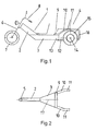
- the tricycle motor vehicle has a frame 1, which a frame front part 2, a horizontally extending frame middle part 3 and there is a rear frame part 4.
- the frame front part 2 consists of a integrally formed tubular frame on which a steering head 5 Front fork 6 with front wheel 7 and handlebar 8 is arranged.
- the frame middle part 3 has an approximately triangular or trapezoidal shape in plan view Form and is formed over its entire area as a hollow body. This Hollow body serves as a tank, the walls of the hollow body being reinforced and have a wall thickness of about 6 mm.
- the rear frame part 4 which consists of a first horizontally extending Support section 9, a second arcuate support section 10 and one third horizontally extending support section 11.
- the rear frame part 4 serves as a suspension for a drive unit 12, not shown in FIG. 1, which between a frame rear part sides end 13 of the frame middle part 3 and a rear axle 14 for the two rear wheels 15 is arranged.
- an engine protection bar 16 which is U-shaped is formed and the third carrier section 11 with the lower rear part End 13 of the frame middle part 3 connects.
- the Carrier section 9 on the top of the frame rear end 13 of the Frame middle part 3 attached and extends transversely to a longitudinal axis 17 of the Frame 1.
- At each end of the support section 9 closes symmetrically Longitudinal axis 17 on a carrier section 10.
- Each carrier section 10 runs in an angle of about 20 degrees to the longitudinal axis 17 towards the rear and in one Angles from about 30 degrees to 45 degrees to the longitudinal plane are always arched decreasing slope upwards.
- Each carrier section 10 closes The carrier section 11 runs parallel to the longitudinal axis 17.
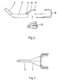
- Another embodiment shown is an additional tank 18 on the Frame rear part 4 arranged.
- the auxiliary tank 18 extends over the first Support section 9 and the second support section 10. If a hollow body as Tank is not provided, the additional tank 18 can be used as a tank.
- the frame 1 is like this designed that the drive unit 12 can be installed in a simple manner.
- the drive unit 12 is complete with the axis, a Y-beam and one Exhaust position inserted in the rear frame part 4 and screwed to the frame.
- the engine protection bar 16 is then attached, as are the rear wheels 15 and the front wheel fork 6 with front wheel 7 and handlebar 8 mounted.
- the carrier section 9 on a rear wall 19 of the frame rear end 13 of the Frame middle part attached and extends from an underside 20 of the Middle frame part 3 starting vertically upwards.
- the carrier section 9 is approximately tubular and is approximately in the area of the base corners 21 of the triangular frame middle part 3 welded.
- On each support section 9 the carrier section closes symmetrically to the longitudinal axis 17 of the frame 1 10 and then the support section 11.
- the carrier sections 10 and 11 run approximately horizontal and together with the carrier section 9 each form an approximately right angle suspension for the drive unit 12 symmetrical on each side Longitudinal axis 17.
- a cooler 23 for the engine sits on the Y-beam 22.
- the cooler 23 is close to that End 13 of the frame rear part 3 on the Y-beam arranged.
- the cooler 23 runs transverse to the longitudinal axis 17 of the frame 1 and is seated approximately between the two support sections 10 of the suspension and in front of the Drive unit 12.
- ventilation slots are provided for cooling the cooler 23 are in a body, which in the drawing is not shown in detail and which in the area of Frame middle part 3 and the frame rear part 4 is seated.
- the ventilation slots are located on the side next to a front seat of the body.
- the airstream enters through the ventilation slots and is sent to the cooler 23 forwarded so that it is cooled from the front by the airstream.
- the Engine protection bar 16 is U-shaped and connects the third Carrier section 11 with the lower end 13 of the rear frame part Frame middle part 3, wherein the lower end 24 of the engine protection bar 16 in Area of the underside 20 of the frame rear end 13 is attached.
- the engine protection bar 16 has increased stability and thus enables a quick, simple and inexpensive attachment of the trailer hitch 25. Furthermore, a dummy tank 27 for receiving from is on the frame front part 2 Instrument clusters or measuring instruments such as tachometers or the like or electronic switching units provided. Be through the dummy tank 27 the instruments are added mirror-free and splash-proof.
Landscapes
- Engineering & Computer Science (AREA)
- Mechanical Engineering (AREA)
- Automatic Cycles, And Cycles In General (AREA)
- Arrangement Of Transmissions (AREA)
Abstract
Description
Die Erfindung bezieht sich auf einen Dreiradkraftwagen mit einem Rahmen, welcher aus einem Rahmenvorderteil, einem horizontal verlaufenden Rahmenmittelteil und einem Rahmenhinterteil besteht, wobei eine Antriebseinheit im Bereich des Rahmenhinterteils angeordnet ist.The invention relates to a tricycle with a frame, which from a frame front part, a horizontally running frame middle part and there is a rear frame part, a drive unit in the area of Frame rear part is arranged.
Ein derartiger bekannter Dreiradkraftwagen, auch "Trike" genannt, stellt eine Mischung zwischen einem Kraftfahrzeug und einem Motorrad dar. Der hintere Teil des Dreiradkraftwagens ist kraftfahrzeugähnlich aufgebaut und weist einen VW-Käfer-Motor auf, während der vordere Teil des Fahrzeuges dem Aufbau eines Motorrad ähnelt. Die Hinterräder sind kräftig ausgebildet und weisen Reifen mit sehr großem Querschnitt auf, während das Vorderrad einen kleinen Reifenquerschnitt aufweist und in einer Vorderradgabel wie bei einem Motorrad gelagert ist. Der gesamte Rahmen ist massiv ausgebildet. Dies führt nachteiligerweise dazu, daß der bekannte Dreiradkraftwagen sehr schwer ist.Such a known three-wheeled motor vehicle, also called "trike", represents one Mix between a motor vehicle and a motorcycle. The rear part The tricycle motor vehicle is built like a motor vehicle and has a VW Beetle engine on while the front part of the vehicle is building a Motorbike resembles. The rear wheels are strong and have tires with a lot large cross-section while the front wheel has a small tire cross-section has and is stored in a front fork like a motorcycle. The entire frame is solid. This leads disadvantageously to the fact that known tricycle motor vehicle is very heavy.
Die Aufgabe der Erfindung besteht somit darin, den Dreiradkraftwagen der eingangs genannten Art derart weiterzuentwickeln, daß sein Gewicht reduziert wird.The object of the invention is therefore the tricycle of the beginning mentioned type to develop in such a way that its weight is reduced.
Zur Lösung dieser Aufgabe wird erfindungsgemäß vorgeschlagen, daß bei dem
Dreiradkraftwagen gemäß dem Oberbegriff des Anspruchs 1 im Rahmenmittelteil ein
Hohlkörper vorgesehen ist. Durch die Ausbildung eines Hohlkörpers im
Rahmenmittelteil wird das Gesamtgewicht verringert, wobei gleichzeitig die
Rahmenstabilität erhalten bleibt. Der Hohlkörper kann auch eine Tankattrappe zur
Aufnahme von Meßgeräten wie Drehzahlmesser oder dergleichen oder
elektronischen Schalteinheiten sein.To solve this problem, the invention proposes that the
Tricycle motor vehicle according to the preamble of
Um eine zusätzliche Gewichtsersparnis zu erreichen, sieht eine Weiterbildung der Erfindung vor, daß sich der Hohlkörper etwa über den Gesamtbereich des Rahmenmittelteils erstreckt, so daß das Rahmenmittelteil vollständig als Hohlkörper ausgebildet ist.In order to achieve additional weight savings, a further training sees the Invention before that the hollow body over about the entire area of Frame middle part extends so that the frame middle part completely as a hollow body is trained.
Bei einer Weiterbildung der Erfindung ist das Rahmenmittelteil im Querschnitt rechteckförmig und in der Draufsicht dreieckförmig oder trapezförmig ausgebildet. In a further development of the invention, the frame middle part is in cross section rectangular and triangular or trapezoidal in plan view.
Die Basis der Dreiecksform schließt an das Rahmenhinterteil an, während die Spitze der Dreiecksform dem Rahmenvorderteil zugewandt ist. Hierdurch wird eine stabile und optisch ansprechende Rahmenkonstruktion erreicht.The base of the triangular shape connects to the rear part of the frame, while the tip the triangular shape faces the front of the frame. This will make it stable and visually appealing frame construction achieved.
Eine besonders bevorzugte Ausführungsform der Erfindung sieht vor, daß der Hohlkörper zur Kraftstoffaufnahme als Tank ausgebildet ist. Bei bisher bekannten Dreiradkraftwagen ist der Tank als separates Bauteil entweder im Bereich des Rahmenhinterteils über der Hinterachse oder oben auf dem Rahmenvorderteil angeordnet. Mit der Tankanordnung im Bereich des tiefliegenden Rahmenmittelteils wird nun einerseits der Schwerpunkt des Dreiradkraftwagens mehr zur Mitte und nach unten hin verschoben, so daß durch den tieferen Schwerpunkt eine verbesserte Fahrstabilität erreicht wird. Weiterhin entfällt ein separates Bauteil, da der Tank im Rahmenmittelteil integriert ist.A particularly preferred embodiment of the invention provides that the Hollow body for receiving fuel is designed as a tank. With previously known The tricycle is the tank as a separate component either in the area of the Rear frame part above the rear axle or on top of the front frame part arranged. With the tank arrangement in the area of the low-lying frame middle section on the one hand, the center of gravity of the tricycle motor vehicle becomes more towards the center and shifted downwards so that a through the lower center of gravity improved driving stability is achieved. Furthermore, there is no separate component, because the tank is integrated in the middle part of the frame.
Eine weitere besonders bevorzugte Ausführungsform der Erfindung sieht vor, daß die Antriebseinheit zwischen der Hinterachse und dem rahmenhinterteilseitigen Ende des Rahmenmittelteils angeordnet ist. Durch diese Anordnung der Antriebseinheit wird der Schwerpunkt des Kraftradwagens weiter zur Mitte hin verschoben, so daß der Dreiradkraftwagen leichter gebaut werden kann. Bei dem bisher bekannten Dreiradkraftwagen war der VW-Motor hinter der Hinterachse angeordnet, wodurch es erforderlich war, die Rahmenteile insgesamt massiv auszuführen, damit der Schwerpunkt nicht zu weit hinten liegt.Another particularly preferred embodiment of the invention provides that the drive unit between the rear axle and the rear frame part End of the frame middle part is arranged. By this arrangement the The drive unit becomes the center of gravity of the motorcycle further towards the center moved so that the tricycle motor vehicle can be built more easily. In which Previously known three-wheelers were the VW engine behind the rear axle arranged, which made it necessary to massively frame the frame parts so that the center of gravity is not too far behind.
Um die Antriebseinheit mit möglichst geringem Montageaufwand an den vorgefertigten Rahmen anzubauen, sieht eine weitere Ausgestaltung der Erfindung vor, daß das Rahmenhinterteil eine Aufhängung für die Antriebseinheit aufweist, wobei die Aufhängung aus einem ersten horizontal verlaufenden Trägerabschnitt und einem damit verbundenen zweiten bogenförmigen Trägerabschnitt besteht, welcher vom ersten Trägerabschnitt ausgehend bogenförmig nach oben verläuft und in einem dritten horizontal verlaufenden Trägerabschnitt endet. Es sind auch andere Ausgestaltungen der Aufhängung denkbar. So besteht bei einer weiteren Ausführungsform der Erfindung die Aufhängung aus einem ersten vertikal verlaufenden Trägerabschnitt, einem damit verbundenen zweiten Trägerabschnitt und einem dritten horizontal verlaufenden Trägerabschnitt. To the drive unit with the least possible assembly effort on the Growing prefabricated frames provides a further embodiment of the invention before that the rear frame part has a suspension for the drive unit, the suspension consisting of a first horizontally extending support section and a second arcuate support section connected thereto, which, starting from the first support section, runs upward in an arc shape and ends in a third horizontally extending support section. There are others too Configurations of the suspension conceivable. So there is another Embodiment of the invention the suspension from a first vertical extending support section, a second support section connected thereto and a third horizontally extending support section.
Bei einer Weiterbildung der Erfindung weist die Antriebseinheit einen abgasarmen Motor mit automatisiertem sequentiellen 6 Gang Getriebe auf, wobei es sich bei dem Motor um einen 3-Zylinder Motor handelt. Dieser Motor in Verbindung mit der verbesserten Rahmenkonstruktion reduziert das Gesamtgewicht gegenüber der herkömmlichen Käfertechnik um etwa 30 %. Weiterhin wird der Benzinverbrauch gegenüber der herkömmlichen Technik um mehr als die Hälfte von durchschnittlich 11 Liter auf 4 Liter pro 100km gesenkt. Die Schaltung des Getriebes erfolgt vorteilhafterweise über eine Tiptronikschaltung, welche am Lenker angeordnet ist, wobei an einem Lenkerteil, beispielsweise dem linken Lenkerteil, der Schaltungsbereich für das Schalten der Gänge nach unten, und an dem anderen Lenkerteil, beispielsweise dem rechten Lenkerteil, der Schaltungsbereich für das Schalten der Gänge nach oben angeordnet ist. Durch die schwerpunktmäßige günstige Anordnung der Antriebseinheit und des Tanks ist ein massives Rahmenvorderteil nicht mehr notwendig, so daß zweckmässigerweise das Rahmenvorderteil als ein Rohrrahmen ausgebildet ist. Bei einem anderen Ausführungsbeispiel der Erfindung ist auf dem Rahmenhinterteil ein Zusatztank angeordnet, um den Aktionsradius des Dreiradkraftwagens ohne Nachtanken zu erhöhen. Es ist auch denkbar, den eigentlichen Tank auf dem Rahmenhinterteil anzuordnen.In a development of the invention, the drive unit has a low-emission Engine with automated sequential 6-speed gearbox, which is the Engine is a 3-cylinder engine. This engine in conjunction with the improved frame construction reduces the overall weight compared to the conventional beetle technology by about 30%. Petrol consumption continues compared to conventional technology by more than half of average Lowered 11 liters to 4 liters per 100km. The gearbox is shifted advantageously via a tiptronic circuit, which is arranged on the handlebar, being on a handlebar part, for example the left handlebar part Shift range for shifting gears down, and on the other Handlebar part, such as the right handlebar part, the circuit area for the Shifting the gears is arranged upwards. Due to the focus favorable arrangement of the drive unit and the tank is a massive one Front part of the frame is no longer necessary, so that expediently Frame front part is designed as a tubular frame. Another one Embodiment of the invention is an additional tank on the rear frame part arranged to close the radius of action of the tricycle without refueling increase. It is also conceivable to put the actual tank on the rear part of the frame to arrange.
Eine bevorzugte Ausführungsform der Erfindung sieht vor, daß im Rahmenhinterteil ein Kühler nahe dem rahmenhinterteilseitigen Ende des Rahmenmittelteils angeordnet ist. Bei dem Kühler handelt es sich um einen Wasserkühler. Um den Kühler in einfacher Weise zusammen mit der Antriebseinheit auszutauschen, sieht eine weitere Ausführungsform der Erfindung vor, daß der Kühler auf einem Y-Träger der Antriebseinheit angeordnet ist und sich quer zu einer Längsachse des Rahmens erstreckt. Vorteilhafterweise sind in einer Karosserie Lüftungsschlitze zur Kühlung des Kühlers vorgesehen. Als Stoßstange oder um die Stabilität des Rahmens zu erhöhen, ist ein Motorschutzbügel vorgesehen, welcher teilweise unter der Antriebseinheit verläuft und mit einem Ende an dem rahmenhinterteilseitigen Ende des Rahmenmittelteils befestigt ist.A preferred embodiment of the invention provides that in the rear frame part a cooler near the frame rear part end of the frame middle part is arranged. The cooler is a water cooler. To the Exchanging the cooler together with the drive unit in a simple manner a further embodiment of the invention that the cooler on a Y-beam the drive unit is arranged and transversely to a longitudinal axis of the frame extends. Ventilation slots for cooling are advantageously in a body the cooler. As a bumper or to ensure the stability of the frame increase, an engine protection bar is provided, which is partially under the Drive unit runs and with one end at the end of the frame rear part the frame middle part is attached.
Die Erfindung wird nachstehend anhand der Zeichnung näher erläutert. Die
Zeichnung zeigt Ausführungsbeispiele der Erfindung. Hierbei stellen dar:
Der erfindungsgemäße Dreiradkraftwagen weist einen Rahmen 1 auf, welcher aus
einem Rahmenvorderteil 2, einen horizontal verlaufenden Rahmenmittelteil 3 und
einen Rahmenhinterteil 4 besteht. Das Rahmenvorderteil 2 besteht aus einem
einstückig ausgebildeten Rohrrahmen, an welchem an einem Lenkkopf 5 eine
Vorderradgabel 6 mit Vorderrad 7 und Lenker 8 angeordnet ist. Das
Rahmenmittelteil 3 hat in Draufsicht eine etwa dreieckförmige oder trapezförmige
Form und ist über seinen Gesamtbereich als Hohlkörper ausgebildet. Dieser
Hohlkörper dient als Tank, wobei die Wände des Hohlkörpers verstärkt sind und
eine Wandstärke von etwa 6 mm aufweisen. An das Rahmenmittelteil 3 schließt sich
das Rahmenhinterteil 4 an, welches aus einem ersten horizontal verlaufenden
Trägerabschnitt 9, einem zweiten bogenförmigen Trägerabschnitt 10 und einem
dritten horizontal verlaufenden Trägerabschnitt 11 besteht. Das Rahmenhinterteil 4
dient als Aufhängung für eine in Fig.1 nicht näher dargestellte Antriebseinheit 12,
welche zwischen einem rahmenhinterteilseiten Ende 13 des Rahmenmittelteils 3 und
einer Hinterachse 14 für die beiden Hinterräder 15 angeordnet ist. An das
Rahmenhinterteil 4 schließt sich ein Motorschutzbügel 16 an, welcher U-förmig
ausgebildet ist und den dritten Trägerabschnitt 11 mit dem unteren hinterteilseitigen
Ende 13 des Rahmenmittelteils 3 verbindet. Wie in Fig.2 dargestellt, ist der
Trägerabschnitt 9 auf der Oberseite des rahmenhinterteilseitigen Endes 13 des
Rahmenmittelteils 3 angebracht und erstreckt sich quer zu einer Längsachse 17 des
Rahmens 1. An jedem Ende des Trägerabschnitts 9 schließt sich symmetrisch zur
Längsachse 17 ein Trägerabschnitt 10 an. Jeder Trägerabschnitt 10 verläuft in
einem Winkel von etwa 20 Grad zur Längsachse 17 nach hinten außen und in einem
Winkel von etwa 30 Grad bis 45 Grad zur Längsebene bogenförmig mit immer
geringer werdender Steigung nach oben. An jeden Trägerabschnitt 10 schließt sich
parallel zur Längsachse 17 verlaufend der Trägerabschnitt 11 an. Bei dem in Fig.5
dargestellten weiteren Ausführungsbeispiel ist ein Zusatztank 18 auf dem
Rahmenhinterteil 4 angeordnet. Der Zusatztank 18 erstreckt sich über den ersten
Trägerabschnitt 9 und den zweiten Trägerabschnitt 10. Wenn ein Hohlkörper als
Tank nicht vorgesehen ist, so kann der Zusatztank 18 als Tank verwendet werden.The tricycle motor vehicle according to the invention has a
Durch die Tankanordnung im Rahmenmittelteil in Form des Hohlkörpers entfällt das
bisher bei bekannten Dreiradkraftwagen verwendete separate Tankbauteil, so daß
bei dem erfindungsgemäße Dreiradkraftwagen eine Gewichtsreduzierung erzielt
wird. Durch die Anordnung der Antriebseinheit 12 vor der Hinterachse 14 wird der
Schwerpunkt gegenüber herkömmlichen Dreiradkraftwagen weiter nach vorne
verlagert, so daß das Rahmenvorderteil 2 nicht mehr massiv, sondern als
Rohrrahmen ausgeführt wird. Hierdurch wird eine weitere Gewichtsreduzierung
erzielt, ohne daß insgesamt die Stabilität des Rahmens 1 beeinträchtigt wird. Als
Antriebseinheit 12 wird ein abgasarmer Motor mit 6-Gang-Getriebe verwendet.
Gegenüber der herkömmlichen Technik ist das Gesamtgewicht des
erfindungsgemäßen Dreiradkraftwagens um etwa 30 % und zusätzlich der
Benzinverbrauch um mehr als die Hälfte von durchschnittlich 11 Liter auf 4 Liter
reduziert. Wie in Fig.3 und 4 schematisch dargestellt, ist der Rahmen 1 so
ausgelegt, daß die Antriebseinheit 12 in einfacher Weise eingebaut werden kann.
Hierzu wird die Antriebseinheit 12 komplett mit der Achse, einem Y-Träger und einer
Auspufflage in das Rahmenhinterteil 4 eingesetzt und mit dem Rahmen verschraubt.
Anschließend wird der Motorschutzbügel 16 angebracht sowie die Hinterräder 15
und die Vorderradgabel 6 mit Vorderrad 7 und Lenker 8 montiert.Due to the tank arrangement in the frame middle part in the form of the hollow body, this is not necessary
separate tank component previously used in known tricycle vehicles, so that
achieved a weight reduction in the tricycle motor vehicle according to the invention
becomes. By arranging the
Bei dem in Fig.6 und Fig.7 dargestellten Ausführungsbeispiel ist der Trägerabschnitt
9 an einer Rückwand 19 des rahmenhinterteilseitigen Endes 13 des
Rahmenmittelteils angebracht und erstreckt sich von einer Unterseite 20 des
Rahmenmittelteils 3 ausgehend vertikal nach oben. Der Trägerabschnitt 9 ist etwa
rohrförmig ausgebildet und ist etwa im Bereich der Basisecken 21 des
dreieckförmigen Rahmenmittelteils 3 angeschweißt. An jeden Trägerabschnitt 9
schließt sich symmetrisch zur Längsachse 17 des Rahmens 1 der Trägerabschnitt
10 und danach der Trägerabschnitt 11 an. Die Trägerabschnitte 10 und 11 verlaufen
etwa horizontal und bilden zusammen mit dem Trägerabschnitt 9 jeweils eine etwa
rechtwinklige Aufhängung für die Antriebseinheit 12 auf jeder Seite symmetrisch zur
Längsachse 17. Zum Einbau wird die Antriebseinheit 12 mit dem Y-Träger 22 in das
Rahmenhinterteil 4 eingesetzt und im Bereich des Trägerabschnitts 11 verschraubt.
Auf dem Y-Träger 22 sitzt ein Kühler 23 für den Motor. Der Kühler 23 ist nahe dem
rahmenhinterteilseitigen Ende 13 des Rahmenmittelteils 3 auf dem Y-Träger
angeordnet. Der Kühler 23 verläuft quer zu Längsachse 17 des Rahmens 1 und sitzt
etwa zwischen den beiden Trägerabschnitten 10 der Aufhängung und vor der
Antriebseinheit 12. Zur Kühlung des Kühlers 23 sind in einer Karosserie, welche in
der Zeichnung nicht näher dargestellt ist und welche im Bereich des
Rahmenmittelteils 3 und des Rahmenhinterteils 4 sitzt, Lüftungsschlitze vorgesehen.
Die Lüftungsschlitze befinden sich seitlich neben einem Vordersitz der Karosserie.
Durch die Lüftungsschlitze tritt der Fahrtwind ein und wird an den Kühler 23
weitergeleitet, so da dieser von vorne durch den Fahrtwind gekühlt wird. Der
Motorschutzbügel 16 ist U-förmig ausgebildet und verbindet den dritten
Trägerabschnitt 11 mit dem unteren rahmenhinterteilseitigen Ende 13 des
Rahmenmittelteils 3, wobei das untere Ende 24 des Motorschutzbügels 16 im
Bereich der Unterseite 20 des rahmenhinterteilseitigen Endes 13 befestigt ist. Durch
diese Rückführung des Motorschutzbügels 16 unter der Antriebseinheit 12 zum
Rahmenmittelteil 3 wird insgesamt die Stabilität des Rahmens erhöht. Weiterhin
werden durch die Rückführung des Motorschutzbügels 16 unter der Antriebseinheit
12 Beschädigungen der Antriebseinheit 12 von der Unterseite her vermieden. Im
hinteren Bereich des Motorschutzbügels 16 ist eine Anhängerkupplung 25
vorgesehen, welche vorteilhafterweise mit dem Motorschutzbügel 16 verschraubt
wird. Der Motorschutzbügel 16 weist eine erhöhte Stabilität auf und ermöglicht somit
eine schnelle, einfache und kostengünstige Anbringung der Anhängerkupplung 25.
Weiterhin ist am Rahmenvorderteil 2 eine Tankattrappe 27 zur Aufnahme von
Kombiinstrumente oder Meßinstrumenten wie Drehzahlmesser oder dergleichen
oder elektronischen Schalteinheiten vorgesehen. Durch die Tankattrappe 27 werden
die Instrumente spiegelfrei und spritzwassergeschützt aufgenommen.In the embodiment shown in FIGS. 6 and 7, the
Claims (16)
dadurch gekennzeichnet, daß im Rahmenmittelteil (3) ein Hohlkörper vorgesehen ist.Tricycle motor vehicle with a frame (1), which consists of a frame front part (2), a horizontally running frame middle part (3) and a frame rear part (4), a drive unit (12) being arranged in the region of the frame rear part (4),
characterized in that a hollow body is provided in the central frame part (3).
dadurch gekennzeichnet, daß sich der Hohlkörper etwa über den Gesamtbereich des Rahmenmittelteils (3) erstreckt.Tricycle motor vehicle according to claim 1,
characterized in that the hollow body extends approximately over the entire area of the frame middle part (3).
dadurch gekennzeichnet, daß das Rahmenmittelteil (3) im Querschnitt rechteckförmig und in der Draufsicht dreieckförmig oder trapezförmig ist.Tricycle motor vehicle according to claim 1 or 2,
characterized in that the frame middle part (3) is rectangular in cross-section and triangular or trapezoidal in plan view.
dadurch gekennzeichnet, daß der Hohlkörper zur Kraftstoffaufnahme als Tank ausgebildet ist.Tricycle motor vehicle according to one of the preceding claims,
characterized in that the hollow body is designed to take up fuel as a tank.
dadurch gekennzeichnet, daß die Antriebseinheit (12) zwischen einer Hinterachse (14) und dem rahmenhinterteilseitigen Ende (13) des Rahmenmittelteils (3) angeordnet ist.Tricycle motor vehicle according to one of the preceding claims,
characterized in that the drive unit (12) is arranged between a rear axle (14) and the frame rear part end (13) of the frame middle part (3).
dadurch gekennzeichnet, daß das Rahmenhinterteil (4) eine Aufhängung für die Antriebseinheit (12) aufweist, wobei die Aufhängung aus einem ersten horizontal verlaufenden Trägerabschnitt (9) und einem damit verbundenen zweiten bogenförmigen Trägerabschnitt (10) besteht, welcher vom ersten Trägerabschnitt (9) ausgehend bogenförmig nach oben verläuft und in einem dritten horizontal verlaufenden Trägerabschnitt (11 ) endet. Tricycle motor vehicle according to one of the preceding claims,
characterized in that the frame rear part (4) has a suspension for the drive unit (12), the suspension consisting of a first horizontally extending support section (9) and a second arcuate support section (10) connected thereto, which is separated from the first support section (9) proceeding upwards in an arc shape and ending in a third horizontally extending support section (11).
dadurch gekennzeichnet, daß das Rahmenhinterteil (4) eine Aufhängung für die Antriebseinheit (12) aufweist, wobei die Aufhängung aus einem ersten vertikal verlaufenden Trägerabschnitt (9), einem damit verbundenen zweiten Trägerabschnitt (10) und einem dritten horizontal verlaufenden Trägerabschnitt (11) besteht.Tricycle motor vehicle according to one of the preceding claims 1 to 5,
characterized in that the frame rear part (4) has a suspension for the drive unit (12), the suspension consisting of a first vertically extending support section (9), a second support section (10) connected thereto and a third horizontally extending support section (11) .
dadurch gekennzeichnet, daß die Antriebseinheit (12) einen abgasarmen Motor aufweist.Tricycle motor vehicle according to one of the preceding claims,
characterized in that the drive unit (12) has a low-emission engine.
dadurch gekennzeichnet, daß das Rahmenvorderteil (2) als Rohrrahmen ausgebildet ist.Tricycle motor vehicle according to one of the preceding claims,
characterized in that the frame front part (2) is designed as a tubular frame.
dadurch gekennzeichnet, daß auf dem Rahmenhinterteil (4) ein Zusatztank (18) angeordnet ist.Tricycle motor vehicle according to one of the preceding claims,
characterized in that an additional tank (18) is arranged on the rear frame part (4).
dadurch gekennzeichnet, daß im Rahmenhinterteil (4) ein Kühler (23) nahe dem hinterteilseitigen Ende (13) des Rahmenmittelteils (3) angeordnet ist.Tricycle motor vehicle according to one of the preceding claims,
characterized in that a cooler (23) is arranged in the rear frame part (4) near the rear end (13) of the frame middle part (3).
dadurch gekennzeichnet, daß der Kühler (23) auf einem Y-Träger (22) der Antriebseinheit (12) angeordnet ist und sich quer zu einer Längsachse (17) des Rahmens (1) erstreckt.Tricycle motor vehicle according to one of the preceding claims,
characterized in that the cooler (23) is arranged on a Y-beam (22) of the drive unit (12) and extends transversely to a longitudinal axis (17) of the frame (1).
dadurch gekennzeichnet, daß in einer Karosserie Lüftungsschlitze zur Kühlung des Kühlers (23) vorgesehen sind. Tricycle motor vehicle according to one of the preceding claims,
characterized in that ventilation slots are provided in a body for cooling the radiator (23).
dadurch gekennzeichnet, daß ein Motorschutzbügel (16) vorgesehen ist, welcher an dem rahmenhinterteilseitigen Ende (13) des Rahmenmittelteils (3) befestigt ist.Tricycle motor vehicle according to one of the preceding claims,
characterized in that a motor protection bracket (16) is provided which is fastened to the end (13) of the frame center part (3) on the rear side of the frame.
dadurch gekennzeichnet, daß an dem Motorschutzbügel (16) eine Anhängerkupplung (25) angeordnet ist.Tricycle motor vehicle according to claim 14,
characterized in that a trailer coupling (25) is arranged on the engine protection bar (16).
dadurch gekennzeichnet, daß das Rahmenvorderteil (2) eine Tankattrappe (26) zur Aufnahme von Instrumenten aufweist.Tricycle motor vehicle according to one of the preceding claims,
characterized in that the frame front part (2) has a dummy tank (26) for receiving instruments.
Applications Claiming Priority (4)
| Application Number | Priority Date | Filing Date | Title |
|---|---|---|---|
| DE10018402 | 2000-04-13 | ||
| DE10018402A DE10018402C1 (en) | 2000-04-13 | 2000-04-13 | Tricycle car |
| DE20014513U | 2000-08-21 | ||
| DE20014513U DE20014513U1 (en) | 2000-04-13 | 2000-08-21 | Tricycle car |
Publications (3)
| Publication Number | Publication Date |
|---|---|
| EP1145945A2 true EP1145945A2 (en) | 2001-10-17 |
| EP1145945A3 EP1145945A3 (en) | 2003-10-15 |
| EP1145945B1 EP1145945B1 (en) | 2004-10-20 |
Family
ID=26005300
Family Applications (1)
| Application Number | Title | Priority Date | Filing Date |
|---|---|---|---|
| EP01108238A Expired - Lifetime EP1145945B1 (en) | 2000-04-13 | 2001-03-31 | Three-wheel motor vehicle |
Country Status (2)
| Country | Link |
|---|---|
| EP (1) | EP1145945B1 (en) |
| AT (1) | ATE280073T1 (en) |
Family Cites Families (11)
| Publication number | Priority date | Publication date | Assignee | Title |
|---|---|---|---|---|
| CH483335A (en) * | 1968-04-18 | 1969-12-31 | Blasi Rosario Di | Folding frame mounted on wheels |
| US4340125A (en) * | 1979-04-05 | 1982-07-20 | Honda Giken Kogyo Kabushiki Kaisha | Stabilized motor vehicle |
| DE3027072A1 (en) * | 1980-07-17 | 1982-03-18 | Florian Dipl.-Ing. 7989 Haslach Windischbauer | Low profile powered tricycle - has single front wheel linked to driven rear wheels by hollow frame section |
| JPS625989Y2 (en) * | 1981-01-27 | 1987-02-10 | ||
| JPS5820581A (en) * | 1981-07-24 | 1983-02-07 | 本田技研工業株式会社 | Frame structure of car |
| FR2582610A1 (en) * | 1985-06-04 | 1986-12-05 | Durand Francois | Motorised utility tricycle |
| JPS6243384A (en) * | 1985-08-21 | 1987-02-25 | 本田技研工業株式会社 | Exhaust duct device for radiator in motor tricycle |
| DE8801923U1 (en) * | 1988-02-15 | 1988-05-05 | Fecht Gmbh, 5207 Ruppichteroth, De | |
| US4944360A (en) * | 1988-03-31 | 1990-07-31 | Sturges Daniel D | Platform oriented transportation vehicle |
| US4909525A (en) * | 1989-01-13 | 1990-03-20 | Michael Flowers | Convertible personal vehicle having a take-apart frame |
| JPH05201363A (en) * | 1992-01-27 | 1993-08-10 | Honda Motor Co Ltd | Sidecar type motor tricycle |
-
2001
- 2001-03-31 AT AT01108238T patent/ATE280073T1/en not_active IP Right Cessation
- 2001-03-31 EP EP01108238A patent/EP1145945B1/en not_active Expired - Lifetime
Non-Patent Citations (1)
| Title |
|---|
| None |
Also Published As
| Publication number | Publication date |
|---|---|
| EP1145945B1 (en) | 2004-10-20 |
| ATE280073T1 (en) | 2004-11-15 |
| EP1145945A3 (en) | 2003-10-15 |
Similar Documents
| Publication | Publication Date | Title |
|---|---|---|
| EP1897793B1 (en) | Motorcycle frame | |
| DE602004013153T2 (en) | MOTORCYCLE | |
| DE2941517A1 (en) | MOTOR VEHICLE WITH TWO FRONT WHEELS | |
| DE19943136A1 (en) | Frame structure for motorcycle, with widening sector locally built up from straight line sector of main frame | |
| DE102006009289A1 (en) | Subframe for attachment to a body of a motor vehicle | |
| DE102017130650A1 (en) | SCHWINGE | |
| DE102009050900B4 (en) | Exhaust system of a motor vehicle | |
| DE102017212790B4 (en) | Connection arrangement for side luggage compartments of a motorcycle | |
| DE19943138B4 (en) | Fuel tank on a two-wheeled motor vehicle | |
| DE3710556A1 (en) | FRAME DESIGN FOR MOTORCYCLE | |
| DE102005057093A1 (en) | Wheel suspension assembly for a commercial vehicle | |
| DE19707282B4 (en) | Device for enhancing the ground pressure of a motorcycle front wheel | |
| DE2658696C2 (en) | Counterweight lift truck with a frame | |
| EP1145945B1 (en) | Three-wheel motor vehicle | |
| DE102021105596B4 (en) | STEP FIXING STRUCTURE | |
| DE102005042177B4 (en) | Vehicle frame with steering arrangement for a commercial vehicle | |
| DE10018402C1 (en) | Tricycle car | |
| DE3019807A1 (en) | MOTORCYCLE | |
| DE102010016730A1 (en) | Control lever for wheel suspension of land craft, particularly longitudinal control arm or rocker arm, has two control lever arms, which are arranged on top of each other and are coupled with each other at their ends arranged side by side | |
| DE102006001709A1 (en) | Bodywork auxiliary frame for motor vehicle e.g. passenger car, has two cross bars, where torsion sections is extended between two cross bars and one cross bar is designed so long that it overlaps lateral swivel bearing | |
| DE60102688T2 (en) | MOTORCYCLE | |
| DE10254458B4 (en) | A vibration-proof structure for a hollow tube for a vehicle | |
| DE102019125195B4 (en) | FRONT PANEL STRUCTURE OF A VEHICLE | |
| DE3432179A1 (en) | MOTORCYCLE | |
| DE102022124612A1 (en) | SADDLE VEHICLE |
Legal Events
| Date | Code | Title | Description |
|---|---|---|---|
| PUAI | Public reference made under article 153(3) epc to a published international application that has entered the european phase |
Free format text: ORIGINAL CODE: 0009012 |
|
| AK | Designated contracting states |
Kind code of ref document: A2 Designated state(s): AT BE CH CY DE DK ES FI FR GB GR IE IT LI LU MC NL PT SE TR |
|
| AX | Request for extension of the european patent |
Free format text: AL;LT;LV;MK;RO;SI |
|
| PUAL | Search report despatched |
Free format text: ORIGINAL CODE: 0009013 |
|
| AK | Designated contracting states |
Kind code of ref document: A3 Designated state(s): AT BE CH CY DE DK ES FI FR GB GR IE IT LI LU MC NL PT SE TR |
|
| AX | Request for extension of the european patent |
Extension state: AL LT LV MK RO SI |
|
| RIC1 | Information provided on ipc code assigned before grant |
Ipc: 7B 62J 35/00 B Ipc: 7B 62K 5/04 A |
|
| 17P | Request for examination filed |
Effective date: 20040217 |
|
| 17Q | First examination report despatched |
Effective date: 20040324 |
|
| GRAP | Despatch of communication of intention to grant a patent |
Free format text: ORIGINAL CODE: EPIDOSNIGR1 |
|
| AKX | Designation fees paid |
Designated state(s): AT BE CH CY DE DK ES FI FR GB GR IE IT LI LU MC NL PT SE TR |
|
| GRAS | Grant fee paid |
Free format text: ORIGINAL CODE: EPIDOSNIGR3 |
|
| GRAA | (expected) grant |
Free format text: ORIGINAL CODE: 0009210 |
|
| AK | Designated contracting states |
Kind code of ref document: B1 Designated state(s): AT BE CH CY DE DK ES FI FR GB GR IE IT LI LU MC NL PT SE TR |
|
| PG25 | Lapsed in a contracting state [announced via postgrant information from national office to epo] |
Ref country code: IT Free format text: LAPSE BECAUSE OF FAILURE TO SUBMIT A TRANSLATION OF THE DESCRIPTION OR TO PAY THE FEE WITHIN THE PRESCRIBED TIME-LIMIT;WARNING: LAPSES OF ITALIAN PATENTS WITH EFFECTIVE DATE BEFORE 2007 MAY HAVE OCCURRED AT ANY TIME BEFORE 2007. THE CORRECT EFFECTIVE DATE MAY BE DIFFERENT FROM THE ONE RECORDED. Effective date: 20041020 Ref country code: IE Free format text: LAPSE BECAUSE OF FAILURE TO SUBMIT A TRANSLATION OF THE DESCRIPTION OR TO PAY THE FEE WITHIN THE PRESCRIBED TIME-LIMIT Effective date: 20041020 Ref country code: TR Free format text: LAPSE BECAUSE OF FAILURE TO SUBMIT A TRANSLATION OF THE DESCRIPTION OR TO PAY THE FEE WITHIN THE PRESCRIBED TIME-LIMIT Effective date: 20041020 Ref country code: FI Free format text: LAPSE BECAUSE OF FAILURE TO SUBMIT A TRANSLATION OF THE DESCRIPTION OR TO PAY THE FEE WITHIN THE PRESCRIBED TIME-LIMIT Effective date: 20041020 Ref country code: NL Free format text: LAPSE BECAUSE OF FAILURE TO SUBMIT A TRANSLATION OF THE DESCRIPTION OR TO PAY THE FEE WITHIN THE PRESCRIBED TIME-LIMIT Effective date: 20041020 |
|
| REG | Reference to a national code |
Ref country code: GB Ref legal event code: FG4D Free format text: NOT ENGLISH |
|
| REG | Reference to a national code |
Ref country code: CH Ref legal event code: EP |
|
| REG | Reference to a national code |
Ref country code: IE Ref legal event code: FG4D Free format text: GERMAN |
|
| REF | Corresponds to: |
Ref document number: 50104164 Country of ref document: DE Date of ref document: 20041125 Kind code of ref document: P |
|
| REG | Reference to a national code |
Ref country code: CH Ref legal event code: NV Representative=s name: PATENTANWAELTE FELDMANN & PARTNER AG |
|
| PG25 | Lapsed in a contracting state [announced via postgrant information from national office to epo] |
Ref country code: GR Free format text: LAPSE BECAUSE OF FAILURE TO SUBMIT A TRANSLATION OF THE DESCRIPTION OR TO PAY THE FEE WITHIN THE PRESCRIBED TIME-LIMIT Effective date: 20050120 Ref country code: SE Free format text: LAPSE BECAUSE OF FAILURE TO SUBMIT A TRANSLATION OF THE DESCRIPTION OR TO PAY THE FEE WITHIN THE PRESCRIBED TIME-LIMIT Effective date: 20050120 Ref country code: DK Free format text: LAPSE BECAUSE OF FAILURE TO SUBMIT A TRANSLATION OF THE DESCRIPTION OR TO PAY THE FEE WITHIN THE PRESCRIBED TIME-LIMIT Effective date: 20050120 |
|
| PG25 | Lapsed in a contracting state [announced via postgrant information from national office to epo] |
Ref country code: ES Free format text: LAPSE BECAUSE OF FAILURE TO SUBMIT A TRANSLATION OF THE DESCRIPTION OR TO PAY THE FEE WITHIN THE PRESCRIBED TIME-LIMIT Effective date: 20050131 |
|
| GBT | Gb: translation of ep patent filed (gb section 77(6)(a)/1977) |
Effective date: 20050114 |
|
| PG25 | Lapsed in a contracting state [announced via postgrant information from national office to epo] |
Ref country code: LU Free format text: LAPSE BECAUSE OF NON-PAYMENT OF DUE FEES Effective date: 20050331 Ref country code: MC Free format text: LAPSE BECAUSE OF NON-PAYMENT OF DUE FEES Effective date: 20050331 Ref country code: CY Free format text: LAPSE BECAUSE OF FAILURE TO SUBMIT A TRANSLATION OF THE DESCRIPTION OR TO PAY THE FEE WITHIN THE PRESCRIBED TIME-LIMIT Effective date: 20050331 |
|
| NLV1 | Nl: lapsed or annulled due to failure to fulfill the requirements of art. 29p and 29m of the patents act | ||
| REG | Reference to a national code |
Ref country code: IE Ref legal event code: FD4D |
|
| PLBE | No opposition filed within time limit |
Free format text: ORIGINAL CODE: 0009261 |
|
| STAA | Information on the status of an ep patent application or granted ep patent |
Free format text: STATUS: NO OPPOSITION FILED WITHIN TIME LIMIT |
|
| ET | Fr: translation filed | ||
| 26N | No opposition filed |
Effective date: 20050721 |
|
| PGFP | Annual fee paid to national office [announced via postgrant information from national office to epo] |
Ref country code: FR Payment date: 20060222 Year of fee payment: 6 |
|
| PGFP | Annual fee paid to national office [announced via postgrant information from national office to epo] |
Ref country code: AT Payment date: 20060302 Year of fee payment: 6 |
|
| PGFP | Annual fee paid to national office [announced via postgrant information from national office to epo] |
Ref country code: BE Payment date: 20060308 Year of fee payment: 6 |
|
| PGFP | Annual fee paid to national office [announced via postgrant information from national office to epo] |
Ref country code: CH Payment date: 20060626 Year of fee payment: 6 |
|
| PGFP | Annual fee paid to national office [announced via postgrant information from national office to epo] |
Ref country code: DE Payment date: 20070307 Year of fee payment: 7 |
|
| REG | Reference to a national code |
Ref country code: CH Ref legal event code: PFA Owner name: FISCHER, JOSEF Free format text: FISCHER, JOSEF#MAX-IMMELMANN-ALLEE 525#79427 ESCHBACH (DE) -TRANSFER TO- FISCHER, JOSEF#MAX-IMMELMANN-ALLEE 525#79427 ESCHBACH (DE) |
|
| REG | Reference to a national code |
Ref country code: CH Ref legal event code: PL |
|
| PG25 | Lapsed in a contracting state [announced via postgrant information from national office to epo] |
Ref country code: AT Free format text: LAPSE BECAUSE OF NON-PAYMENT OF DUE FEES Effective date: 20070331 |
|
| GBPC | Gb: european patent ceased through non-payment of renewal fee |
Effective date: 20070331 |
|
| BERE | Be: lapsed |
Owner name: *FISCHER JOSEF Effective date: 20070331 |
|
| PG25 | Lapsed in a contracting state [announced via postgrant information from national office to epo] |
Ref country code: BE Free format text: LAPSE BECAUSE OF NON-PAYMENT OF DUE FEES Effective date: 20070331 Ref country code: PT Free format text: LAPSE BECAUSE OF NON-PAYMENT OF DUE FEES Effective date: 20050320 |
|
| REG | Reference to a national code |
Ref country code: FR Ref legal event code: ST Effective date: 20071130 |
|
| PG25 | Lapsed in a contracting state [announced via postgrant information from national office to epo] |
Ref country code: LI Free format text: LAPSE BECAUSE OF NON-PAYMENT OF DUE FEES Effective date: 20070331 Ref country code: CH Free format text: LAPSE BECAUSE OF NON-PAYMENT OF DUE FEES Effective date: 20070331 |
|
| PG25 | Lapsed in a contracting state [announced via postgrant information from national office to epo] |
Ref country code: GB Free format text: LAPSE BECAUSE OF NON-PAYMENT OF DUE FEES Effective date: 20070331 |
|
| PG25 | Lapsed in a contracting state [announced via postgrant information from national office to epo] |
Ref country code: FR Free format text: LAPSE BECAUSE OF NON-PAYMENT OF DUE FEES Effective date: 20070402 |
|
| PGFP | Annual fee paid to national office [announced via postgrant information from national office to epo] |
Ref country code: GB Payment date: 20060223 Year of fee payment: 6 |
|
| PG25 | Lapsed in a contracting state [announced via postgrant information from national office to epo] |
Ref country code: DE Free format text: LAPSE BECAUSE OF NON-PAYMENT OF DUE FEES Effective date: 20081001 |