EP1145755A1 - Regenerative type carbon dioxide separator and carbon dioxide separating system - Google Patents
Regenerative type carbon dioxide separator and carbon dioxide separating system Download PDFInfo
- Publication number
- EP1145755A1 EP1145755A1 EP00969965A EP00969965A EP1145755A1 EP 1145755 A1 EP1145755 A1 EP 1145755A1 EP 00969965 A EP00969965 A EP 00969965A EP 00969965 A EP00969965 A EP 00969965A EP 1145755 A1 EP1145755 A1 EP 1145755A1
- Authority
- EP
- European Patent Office
- Prior art keywords
- carbon dioxide
- gas
- dioxide gas
- absorbing
- separating agent
- Prior art date
- Legal status (The legal status is an assumption and is not a legal conclusion. Google has not performed a legal analysis and makes no representation as to the accuracy of the status listed.)
- Withdrawn
Links
Images

Classifications
-
- F—MECHANICAL ENGINEERING; LIGHTING; HEATING; WEAPONS; BLASTING
- F28—HEAT EXCHANGE IN GENERAL
- F28D—HEAT-EXCHANGE APPARATUS, NOT PROVIDED FOR IN ANOTHER SUBCLASS, IN WHICH THE HEAT-EXCHANGE MEDIA DO NOT COME INTO DIRECT CONTACT
- F28D19/00—Regenerative heat-exchange apparatus in which the intermediate heat-transfer medium or body is moved successively into contact with each heat-exchange medium
- F28D19/04—Regenerative heat-exchange apparatus in which the intermediate heat-transfer medium or body is moved successively into contact with each heat-exchange medium using rigid bodies, e.g. mounted on a movable carrier
- F28D19/041—Regenerative heat-exchange apparatus in which the intermediate heat-transfer medium or body is moved successively into contact with each heat-exchange medium using rigid bodies, e.g. mounted on a movable carrier with axial flow through the intermediate heat-transfer medium
- F28D19/042—Rotors; Assemblies of heat absorbing masses
- F28D19/044—Rotors; Assemblies of heat absorbing masses shaped in sector form, e.g. with baskets
-
- B—PERFORMING OPERATIONS; TRANSPORTING
- B01—PHYSICAL OR CHEMICAL PROCESSES OR APPARATUS IN GENERAL
- B01D—SEPARATION
- B01D53/00—Separation of gases or vapours; Recovering vapours of volatile solvents from gases; Chemical or biological purification of waste gases, e.g. engine exhaust gases, smoke, fumes, flue gases, aerosols
- B01D53/14—Separation of gases or vapours; Recovering vapours of volatile solvents from gases; Chemical or biological purification of waste gases, e.g. engine exhaust gases, smoke, fumes, flue gases, aerosols by absorption
-
- B—PERFORMING OPERATIONS; TRANSPORTING
- B01—PHYSICAL OR CHEMICAL PROCESSES OR APPARATUS IN GENERAL
- B01D—SEPARATION
- B01D53/00—Separation of gases or vapours; Recovering vapours of volatile solvents from gases; Chemical or biological purification of waste gases, e.g. engine exhaust gases, smoke, fumes, flue gases, aerosols
- B01D53/02—Separation of gases or vapours; Recovering vapours of volatile solvents from gases; Chemical or biological purification of waste gases, e.g. engine exhaust gases, smoke, fumes, flue gases, aerosols by adsorption, e.g. preparative gas chromatography
- B01D53/06—Separation of gases or vapours; Recovering vapours of volatile solvents from gases; Chemical or biological purification of waste gases, e.g. engine exhaust gases, smoke, fumes, flue gases, aerosols by adsorption, e.g. preparative gas chromatography with moving adsorbents, e.g. rotating beds
-
- C—CHEMISTRY; METALLURGY
- C01—INORGANIC CHEMISTRY
- C01B—NON-METALLIC ELEMENTS; COMPOUNDS THEREOF; METALLOIDS OR COMPOUNDS THEREOF NOT COVERED BY SUBCLASS C01C
- C01B32/00—Carbon; Compounds thereof
- C01B32/50—Carbon dioxide
-
- B—PERFORMING OPERATIONS; TRANSPORTING
- B01—PHYSICAL OR CHEMICAL PROCESSES OR APPARATUS IN GENERAL
- B01D—SEPARATION
- B01D2251/00—Reactants
- B01D2251/30—Alkali metal compounds
-
- B—PERFORMING OPERATIONS; TRANSPORTING
- B01—PHYSICAL OR CHEMICAL PROCESSES OR APPARATUS IN GENERAL
- B01D—SEPARATION
- B01D2251/00—Reactants
- B01D2251/40—Alkaline earth metal or magnesium compounds
-
- B—PERFORMING OPERATIONS; TRANSPORTING
- B01—PHYSICAL OR CHEMICAL PROCESSES OR APPARATUS IN GENERAL
- B01D—SEPARATION
- B01D2251/00—Reactants
- B01D2251/60—Inorganic bases or salts
- B01D2251/602—Oxides
-
- B—PERFORMING OPERATIONS; TRANSPORTING
- B01—PHYSICAL OR CHEMICAL PROCESSES OR APPARATUS IN GENERAL
- B01D—SEPARATION
- B01D2253/00—Adsorbents used in seperation treatment of gases and vapours
- B01D2253/25—Coated, impregnated or composite adsorbents
-
- B—PERFORMING OPERATIONS; TRANSPORTING
- B01—PHYSICAL OR CHEMICAL PROCESSES OR APPARATUS IN GENERAL
- B01D—SEPARATION
- B01D2256/00—Main component in the product gas stream after treatment
- B01D2256/22—Carbon dioxide
-
- B—PERFORMING OPERATIONS; TRANSPORTING
- B01—PHYSICAL OR CHEMICAL PROCESSES OR APPARATUS IN GENERAL
- B01D—SEPARATION
- B01D2257/00—Components to be removed
- B01D2257/50—Carbon oxides
- B01D2257/504—Carbon dioxide
-
- B—PERFORMING OPERATIONS; TRANSPORTING
- B01—PHYSICAL OR CHEMICAL PROCESSES OR APPARATUS IN GENERAL
- B01D—SEPARATION
- B01D2258/00—Sources of waste gases
- B01D2258/02—Other waste gases
- B01D2258/0283—Flue gases
- B01D2258/0291—Flue gases from waste incineration plants
-
- B—PERFORMING OPERATIONS; TRANSPORTING
- B01—PHYSICAL OR CHEMICAL PROCESSES OR APPARATUS IN GENERAL
- B01D—SEPARATION
- B01D2259/00—Type of treatment
- B01D2259/40—Further details for adsorption processes and devices
- B01D2259/40083—Regeneration of adsorbents in processes other than pressure or temperature swing adsorption
- B01D2259/40088—Regeneration of adsorbents in processes other than pressure or temperature swing adsorption by heating
- B01D2259/4009—Regeneration of adsorbents in processes other than pressure or temperature swing adsorption by heating using hot gas
-
- B—PERFORMING OPERATIONS; TRANSPORTING
- B01—PHYSICAL OR CHEMICAL PROCESSES OR APPARATUS IN GENERAL
- B01D—SEPARATION
- B01D53/00—Separation of gases or vapours; Recovering vapours of volatile solvents from gases; Chemical or biological purification of waste gases, e.g. engine exhaust gases, smoke, fumes, flue gases, aerosols
- B01D53/02—Separation of gases or vapours; Recovering vapours of volatile solvents from gases; Chemical or biological purification of waste gases, e.g. engine exhaust gases, smoke, fumes, flue gases, aerosols by adsorption, e.g. preparative gas chromatography
-
- Y—GENERAL TAGGING OF NEW TECHNOLOGICAL DEVELOPMENTS; GENERAL TAGGING OF CROSS-SECTIONAL TECHNOLOGIES SPANNING OVER SEVERAL SECTIONS OF THE IPC; TECHNICAL SUBJECTS COVERED BY FORMER USPC CROSS-REFERENCE ART COLLECTIONS [XRACs] AND DIGESTS
- Y02—TECHNOLOGIES OR APPLICATIONS FOR MITIGATION OR ADAPTATION AGAINST CLIMATE CHANGE
- Y02C—CAPTURE, STORAGE, SEQUESTRATION OR DISPOSAL OF GREENHOUSE GASES [GHG]
- Y02C20/00—Capture or disposal of greenhouse gases
- Y02C20/40—Capture or disposal of greenhouse gases of CO2
-
- Y—GENERAL TAGGING OF NEW TECHNOLOGICAL DEVELOPMENTS; GENERAL TAGGING OF CROSS-SECTIONAL TECHNOLOGIES SPANNING OVER SEVERAL SECTIONS OF THE IPC; TECHNICAL SUBJECTS COVERED BY FORMER USPC CROSS-REFERENCE ART COLLECTIONS [XRACs] AND DIGESTS
- Y02—TECHNOLOGIES OR APPLICATIONS FOR MITIGATION OR ADAPTATION AGAINST CLIMATE CHANGE
- Y02P—CLIMATE CHANGE MITIGATION TECHNOLOGIES IN THE PRODUCTION OR PROCESSING OF GOODS
- Y02P20/00—Technologies relating to chemical industry
- Y02P20/151—Reduction of greenhouse gas [GHG] emissions, e.g. CO2
Definitions
- the present invention relates to a regenerative carbon dioxide gas separator and a carbon gas separating system. More particularly, the present invention relates to a regenerative carbon dioxide gas separator and a carbon gas separating system that can separate carbon dioxide gas (CO 2 ) contained in effluent or exhaust gases from combustion boilers and the like in an efficient and economical manner.
- CO 2 carbon dioxide gas
- a fuel such as a petroleum fuel, a coal fuel, LNG (liquid natural gas), etc. is burned in a boiler to generate a considerable volume of carbon dioxide gas.
- Japanese Patent No. 2809368 discloses a method for recovering carbon dioxide gas by the use of an aqueous alkanolamine solution that in nonflammable.
- Japanese Patent No. 2809381 discloses a separation system using a monoethanol amine absorption liquid, in which a heating source of a reboiler of an absorption liquid regeneration tower is optimized.
- absorption efficiency is not so high.
- the volume of carbon dioxide collected by an absorption liquid containing an amine is at most about 20 to 30 times the volume of the absorption liquid. Therefore, in a large-scale combustion plant, an extremely large amount of absorption liquid should always be circulated.
- the allowable temperature that can be tolerated by the absorption liquids and separation membranes used in the above-described methods is about 200 °C.
- heat resistance of such absorption liquids and separation membranes is low. Since the temperature of most effluent gases discharged from various combustion sources, such as a boiler of a thermal plant, is 600 °C or more, it is necessary to provide an effluent gas cooling system before introducing an effluent gas into a carbon dioxide gas separator. Therefore, the system becomes complicated, and the cost for separating carbon dioxide gas becomes high.
- An object of the present invention is to provide a regenerative carbon dioxide gas separator and a carbon dioxide gas separating system that can separate carbon dioxide gas with great efficiency although they have far simpler configuration than conventional apparatuses or systems.
- a regenerative carbon dioxide gas separator includes: a rotatable rotor; an absorbing/separating agent housed in the rotor, for absorbing carbon dioxide gas at a temperature lower than a predetermined temperature, and for releasing the absorbed carbon dioxide gas at a temperature higher than the predetermined temperature; a first gas flow passage for passing a first gas through the rotor in a direction substantially parallel to a central axis of rotations of the rotor; a second gas flow passage for passing a second gas through the rotor in a direction substantially parallel to the central axis of rotations of the rotor; and a sealing mechanism for preventing the mixing of the first gas and the second gas, wherein carbon dioxide gas contained in the first gas is absorbed by the absorbing/separating agent and the carbon dioxide gas absorbed by the absorbing/separating agent is released into the second gas by rotating the rotor while the temperature of the first gas flow passage is set to be lower than the predetermined temperature and the temperature of the second
- the carbon dioxide gas separator may include a plurality of baskets attachable to the rotor, each having an opening in a direction of the gas flows.
- the absorbing/separating agent may be housed in the baskets.
- a regenerative carbon dioxide gas separator includes: a plurality of reaction chambers; an absorbing/separating agent housed in the plurality of reaction chambers, which absorbs carbon dioxide gas at a temperature lower than a predetermined temperature and releases the absorbed carbon dioxide gas at a temperature higher than the predetermined temperature; and switching means for selectively supplying one of first gas and second gas to the plurality of reaction chambers; wherein the regenerative carbon dioxide gas separator sequentially performs in the reaction chambers: absorption cycles in which the first gas is supplied to a reaction chamber to form a first gas flow passage while the temperature of the reaction chamber is maintained to be lower than the predetermined temperature, and the absorbing/separating agent absorbs carbon dioxide gas contained in the first gas; and regeneration cycles in which the second gas is supplied to the reaction chamber to form a second gas flow passage while the temperature of the reaction chamber is maintained to be higher than the predetermined temperature, and the absorbing/separating agent releases the absorbed carbon dioxide gas into the second gas.
- reaction chambers include heating means for heating the absorbing/separating agent to a temperature higher than the predetermined temperature, it is possible to heat the absorbing/separating agent to a temperature higher than the inflection point surely and easily.
- the absorbing/separating agent includes at least one of lithium zirconate, an alkali metal oxide, and an alkali earth metal, it is possible to realize highly efficient absorption/separation.
- the absorbing/separating agent is shaped into any of granular, porous, aggregated, tubular, deformed-plane, and linear shapes, or shaped into an aggregated or plane-structured article having through holes in a direction of the gas flows, it is possible to absorb/separate carbon dioxide gas in an efficient manner.
- the absorbing/separating agent is supported on at least one of granular, porous, aggregated, tubular, deformed-plane, and linear molded article, or an aggregated or place-structured molded article having through holes in a direction of the gas flows, such an article is highly efficient and reliable.
- a carbon dioxide gas separating system includes: any of the above-described regenerative carbon dioxide gas separators; heating means for heating the second gas flow passage of the regenerative carbon dioxide gas separator to a temperature higher than the predetermined temperature; heat recovering means for cooling a gas flowing out of the first gas flow passage; and heat exchanging means for transferring heat energy from a gas containing carbon dioxide gas flowing out of the second gas flow passage to the first gas supplied to the first gas flow passage.
- the carbon dioxide gas separating system may further include circulating means for supplying at least part of the gas containing carbon dioxide gas discharged from the second gas flow passage to the second gas flow passage again, and the heating means may be a regenerative burner or an indirect type of furnace for burning a fuel to heat the gas containing carbon dioxide gas circulated by the circulating means.
- the heat recovering means may include a boiler for generating steam by the use of the gas discharged from the first gas flow passage, or may include the boiler, a steam turbine driven by the steam generated by the boiler, and a generator driven by the steam turbine.
- the heat exchanging means may be a plate-type, tubular-type, or rotary-type of regenerative heat exchanger.
- FIG. 1 is a perspective view showing a regenerative carbon dioxide gas separator according to the present invention.
- a regenerative carbon dioxide gas separator 1 shown in Fig. 1 is of rotating type.
- the separator 1 includes a rotation shaft 1a, a rotor 1b which rotates around the rotation shaft 1a at a predetermined speed in a direction shown by an arrow, and compartments (sometimes called “sectors") 1c housed in the rotor 1b.
- Each compartment 1c is filled with an absorbing/separating agent 1g, which reversibly absorbs or releases carbon dioxide gas in accordance with changes in temperature.
- a compartment 1c may be provided with, e.g., a plurality of baskets ba, which are filled with the absorbing/separating agent 1g.
- each basket ba has an opening in a direction of a gas flow to secure contact between the absorbing/separating agent 1g and carbon dioxide gas.
- the opening of each basket ba may be formed like, e.g., a net or lattice.
- the absorbing/separating agent 1g a material having a characteristic to absorb carbon dioxide gas at a relatively low temperature, and to discharge the absorbed carbon dioxide at a relatively high temperature, is used as the absorbing/separating agent 1g.
- the reference numerals 1d and 1e denote a rotor housing and a sector plate, respectively.
- the separator 1 thus constituted has a high temperature section 1h and a low temperature section 1L, which are provided as partitioned sections around the rotation shaft 1a of the rotor 1b.
- An effluent or exhaust gas G1 discharged from a boiler, an incinerator, etc. (not shown) is supplied to the low temperature section 1L.
- a carrier gas A1 for carrying carbon dioxide gas released from the absorbing/separating agent is supplied to the high temperature section 1h.
- the compartment 1c moves to the high temperature section 1h and contacts the high-temperature carrier gas A1, resulting in that the carbon dioxide gas absorbed by the absorbing/separating agent 1g is released from the absorbing/separating agent 1g, and discharged as a gas flow A2 containing the carbon dioxide gas and the carrier gas.
- the absorbing/separating agent 1g moves to the low temperature section 1L again, and absorbs and separates carbon dioxide gas from the effluent gas G1 again.
- the high temperature section 1h and the low temperature section 1L are sealed by a sealing system, not shown, to prevent leakage of gas. Therefore, the effluent gases G1 and G2, and the carrier gasses A1 and A2 are not mixed with each other.
- the gas flow G1 and the gas flow A1 are parallel to each other, and move downwards. However, they may be parallel to each other and move in opposite directions.
- a heat-resistant stainless steel is used at the high temperature side
- a soft steel or steel for welding structure is used at the low temperature side, as materials of heat exchangers.
- the entire weight of the rotor is supported by a rotor bearing provided below the low temperature side.
- a rotor bearing provided at the upper section allows the thermal expansion in a vertical direction, and supports the rotor only in a horizontal direction.
- This rotating regenerative separator may be installed so that the rotor shaft extends in a horizontal direction.
- carbon dioxide gas contained in an effluent gas can be absorbed and separated by simply rotating the rotor 1b because of the high temperature section 1h and the low temperature section 1L provided on the circumference of the rotor 1b. Therefore, it is possible to obtain an absorbing/separating system, which is highly simplified but reliable. The regeneration costs of such a system can be remarkably reduced, and the maintenance of such a system is easy.
- Lithium zirconate, an alkaline metal oxide, or an alkaline earth metal oxide can be used as the absorbing/separating agent 1g.
- Japanese Patent Laid-Open Pub. Nos. 99214/1997 and 152302/1998 disclose in detail such compounds.
- lithium zirconate i.e., an oxide of lituim (Li) and zirconium (Zr) can be used.
- Li 2 ZrO 3 and Li 4 ZrO 4 can be used.
- the absorbing reaction (1) is remarkable in a temperature range of about 400 °C to about 580 °C.
- the releasing reaction (2) is remarkable in a temperature range of about 600 °C or more. Therefore, if the absorbing/separating agent 1g is placed in the low temperature section in a temperature range of about 400 °C to about 580 °C, the absorbing/separating agent 1g actively absorbs carbon dioxide gas in the effluent gas. If the absorbing/separating agent 1g is moved to the high temperature section in a temperature range of about 600 °C or more, the absorbed carbon dioxide is released.
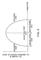
- Fig. 2 is a graph showing a reaction model using Li 2 ZrO 3 as an absorbing/separating agent.
- the abscissa axis of the graph shows the temperature, and the ordinate axis shows the volume of carbon dioxide gas contained in the absorbing/separating agent.
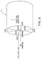
- Fig. 3 conceptually shows operations of a regenerative carbon dioxide gas separator according to the present invention in relation to this embodiment.
- the volume of carbon dioxide contained in the absorbing/separating agent reaches the maximum level at the temperature of about 600 °C. If this temperature is determined as the "inflection point", the volume of carbon dioxide is reduced in both the temperature ranges higher and lower the inflection point.
- the reaction for absorbing the carbon dioxide gas expressed by the above formula (1) starts, emitting heat of reaction. If contacting more carbon dioxide gas, the absorbing/separating agent keeps absorbing carbon dioxide gas and is heated by the heat energy until the temperature thereof reaches the inflection point, i.e., 600 °C.
- the volume of carbon dioxide contained in the absorbing/separating agent is at the maximum level, thereby stopping the absorbing reaction. If the absorbing/separating agent is further heated, it starts releasing carbon dioxide gas while absorbing the heat energy as heat of reaction, as expressed in the above formula (2). The releasing of carbon dioxide gas continues until the temperature of the absorbing/separating agent reaches about 700 °C, at which the volume of carbon dioxide contained in the absorbing/separating agent reaches the minimum level.
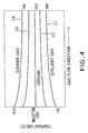
- Fig. 4 is a graph showing an example of internal temperature distribution of a gas flow in a regenerative carbon dioxide gas separator according to the present invention.
- the absorbing/separating agent 1g absorbs carbon dioxide gas, thereby raising the temperature thereof by heat of reaction, as shown by a curved line C1.
- the temperature of the effluent gas G2 is about 388 °C.
- the temperature distribution of an effluent gas in the temperature range of higher than 145 °C and lower than the inflection point is between the curved line C1 and the inflection point.
- the absorbing/separating agent 1g releases carbon dioxide gas by absorbing the heat energy as heat of reaction, thereby lowering the temperature thereof, as shown by a curved line C4 in Fig. 4.
- the temperature of the carrier gas A2 is about 795°C.
- the temperature distribution of a carrier gas in the temperature range of lower than 1072°C and higher than the inflection point is between the curved line C4 and the inflection point.
- 1 mol of solid absorbing/separating agent can absorb 1 mol of carbon dioxide gas.
- the absorbing/separating agent can absorb 400 times its own volume of carbon dioxide gas. If an absorbing liquid including an amine, mentioned in the descriptions of the conventional techniques, is used, the volume of carbon dioxide the absorbing liquid can absorb is about 20 times the volume of the absorbing liquid.
- an alkali metal oxide etc. as the absorbing/separating agent, it is possible to absorb more than 10 times of carbon dioxide than the conventional absorbing liquid. Therefore, it is possible to obtain a recovery system which is far small in volume but is highly efficient.
- Li 2 ZrO 3 and Li 4 ZrO 4 e.g., Li 2 O or Na 2 O can be used as an alkali metal oxide of the absorbing/separating agent 1g of the present invention.
- the following absorbing/releasing reactions occur between Li 2 O and carbon dioxide gas: Li 2 O(s) + CO 2 (g) ⁇ Li 2 CO 3 (l) Li 2 CO 3 (l) ⁇ Li 2 O(s) + CO 2 (g)
- the absorbing reaction (3) is remarkable in a temperature range of about 700 °C to about 1000 °C.
- the releasing reaction (4) is remarkable in a temperature range of about 1100 °C or more. Therefore, if the absorbing/separating agent 1g is placed in the low temperature section in a temperature range of about 700 °C to about 1000 °C, the absorbing/separating agent 1g actively absorbs carbon dioxide gas in the effluent gas. If the absorbing/separating agent 1g is moved to the high temperature section in a temperature range of 1100 °C or more, the absorbed carbon dioxide is released.
- the absorbing reaction (3) is remarkable in a temperature range of about 700 °C to about 1700 °C.
- the releasing reaction (4) is remarkable in a temperature range of about 1800 °C or more.
- an alkali earth metal oxide which is the other material of the absorbing/separating agent 1g
- MgO or CaO can be used as an alkali earth metal oxide.
- the absorbing reaction is remarkable in a temperature range of about 300 °C to about 400 °C.
- the releasing reaction is remarkable in a temperature range of about 800 °C or more.
- a separator according to the present invention has an internal temperature distribution along a gas flow, as shown in Fig. 4. Therefore, if, in each temperature range, a material that can absorb carbon dioxide gas most effectively in that temperature range is provided, it is possible to further improve the absorbing efficiency.
- some absorbing/separating agents may be deposited so that the inflection point varies in accordance with the temperature distribution of the effluent gas.
- the absorbing/separating agent 1g containing solid Li 2 ZrO 3 absorbs carbon dioxide gas to generate solid ZrO 2 and liquid Li 2 CO 3 .
- an absorbing/separating agent such as lithium zirconate obtained as fine particles with the average particle diameter of 0.01 ⁇ m to a few ⁇ m is shaped to be grains or a porous article.
- Both of the above states are chemically and mechanically stable, and can absorb and release carbon dioxide gas stably and reversibly.
- molded articles of such a power, granular, or porous absorbing/separating agent by processing it into an aggregated, tubular, deformed-plane, or linear shape.
- a molded article in an aggregated or plane-structured shape having through holes in a direction of a gas flow like honeycomb-shape or briquette-shape.
- a supporting article obtained by shaping a ceramic material or metal into one of the above-described shapes supports an absorbing/separating agent on its surfaces. That is, it is possible that an absorbing/separating agent is supported on the surfaces of a molded article made of a ceramic material or metal in a granular, porous, aggregated, tubular, deformed-plane, or linear shape by means of applying, adhering, sticking, or coating. For example, it is possible to apply an absorbing/separating agent to a porous (particulate) material such as zeolite.
- an absorbing/separating agent is supported on the surfaces of a molded article made of a ceramic material or metal, formed in an aggregated or plane-structured shape having through holes in a direction of gas flow, such as a honeycomb or briquette.
- such a molded article or supporting article is formed in a shape to increase the contact area with gases, and to improve filling efficiency.
- Molded articles or supporting articles in an aggregated shape having openings in a direction of gas flow may be referred to as various kinds of element blocks having circular, square, triangular, honeycomb, and star-shaped sections.
- Japanese Patent No. 2879599 discloses the above-described shapes.
- Molded articles or supporting articles in a plane-structured shape having through holes in a direction of gas flow may be called as articles made by combining a plurality of flat sheets and wave-shape sheets and positioning them in parallel to a direction of gas flow, or a various kinds of element plates having wave-shaped sections.
- Japanese Patent No. 2660577, Japanese Patent Laid-Open Pub. Nos. 280761/1997 and 316608/1997, and Japanese Design Publication Nos. 721191 (K6-592) and 721191 similar 1 (K6-592 A similar) disclose such plane-structured shapes.
- the outer dimensions of such molded or supporting articles are, e.g., in a range of a few centimeters to a few tens of centimeters. Since the outer dimensions of the rotor 1b of the carbon dioxide gas separator shown in Fig. 1 are in a range of more than a few meters, a number of molded articles or supporting articles are loaded in the baskets of the compartments 1c.
- the height of the rotor 1b is more than a few meters, having a plurality of baskets in a direction of gas flow, as shown in Fig. 1, may facilitate loading and replacing absorbing/separating agent. If net-like or lattice-like partitions are provided to each basket, the baskets can hold the absorbing/separating agent in a secured manner. Alternatively, a single basket may be provided along a direction of gas flow, and inside of the basket may be divided by lattice-like elements along the gas flow to load the absorbing/separating agent.
- molded or supporting articles in an aggregated or plane-structured shape having through holes in a gas flow, with a length identical with the depth (gas-flow direction) of a basket may be arranged in the basket.
- molded or supporting articles with a length shorter than the depth of the basket may be arranged in a few layers.
- molded or supporting articles having different sections or shapes may be combined to be loaded in the compartments.
- a granular article and an aggregated article may be combined, or a linear article and a plane-structured article may be combined to be loaded in the compartments.
- an absorbing/separating agent may be formed as an enamel element supplied by ABB ALSTOM Power K.K.
- the term "enamel element” represents elements obtained by laminating enameled wave-shape steel sheets. The structures of such elements are disclosed in, e.g., Japanese Patent No. 2660577, Japanese Patent Laid-Open Pub. Nos. 280761/1997 and 316608/1997, Japanese Design Publication Nos. 721191 (K6-592) and 721191 similar 1 (K6-592 A similar).
- enamel elements supplied from ABB ALSTOM Power K.K. are advantageous since they cause little pressure loss, stand a mass volume of air flow, and achieve high contact efficiency with effluent gasses.
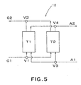
- FIG. 5 conceptually shows the structure of the main part of a fixed regenerative carbon dioxide gas separator according to the present invention.
- a carbon dioxide separator 10 includes two reaction towers T1 and T2, ducts provided for the communication of the reaction towers, to connect inlet ports and outlet ports of first and second gasses, and selector valves V1 - V4 for shielding and passing the first and second gasses.
- the reaction towers T1 and T2 are filled with an absorbing/separating agent 1g previously mentioned with reference to Figs. 1 to 4.
- An effluent gas G1 is supplied via the selector valve V1 to the reaction tower T1, whose temperature is maintained lower than the inflection point of the absorbing/separating agent.
- carbon dioxide gas contained in the effluent gas G1 is absorbed by the absorbing/separating agent 1g and separated from the effluent gas G1 while the effluent gas G1 passes through the reaction tower T1.
- the rest of the gas i.e., an effluent gas G2 is removed via the selector valve V2 from the outlet of the reaction tower T1.
- the selector valves V1 to V4 are switched to achieve a regenerating cycle in which a high temperature carrier gas A1 is supplied to the reaction tower T1 instead of the effluent gas G1. Then, the carbon dioxide absorbed by the absorbing/separating agent 1g is released, and discharged as a gas flow A2 containing the carbon dioxide gas and the carrier gas. At the same time, the reaction tower T2 is supplied with the effluent gas G1 to continue absorption/separation of carbon dioxide gas.
- carbon dioxide is absorbed and separated by heating the absorbing/separating agent 1g by the use of the high-temperature carrier gas A1.
- heating means such as an electric heater, may be appropriately provided in each reaction tower as additional heating means to heat the absorbing/separating agent 1g to a temperature higher than the inflection point.
- ducts is not limited to the drawn one. Different processing paths may be created by appropriately providing selector valves.
- the number of the reaction towers is not limited to two. Three or more of reaction towers may be combined to constitute a regenerative carbon dioxide gas separator.
- the number of reaction towers may be appropriately determined in accordance with the pressure loss value of the separator, or the amounts of the effluent gas and the carrier gas.
- a third reaction tower may be operated to purge the effluent gas G1 remaining in the ducts and the reaction towers at the time of switching the first and second reaction towers. In this way, unprocessed effluent gas G1 remaining in the ducts and the reaction towers is not discharged or mixed with the carrier gas.
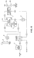
- Fig. 6 conceptually shows the structure of an effluent gas purifying system using a rotating regenerative carbon dioxide gas separator according to the present invention.
- Table 1 shows data, such as kinds of gasses, flow volume, CO 2 volume, temperature, specific heat, and enthalpy of gas flows measured in the gas flow paths of the system employing the rotating regenerative carbon dioxide gas separator shown in Fig. 1.
- Fluid Type of Fluid Flow Volume Co 2 Volume Temperature Specific Heat Enthalpy Measuring Unit/Pos KNm 3 /Hr % °C KCal/Nm3°C Mcal/Hr A Effluent gas 3,000 13.5 100 0.25 279,750 B Effluent gas 3,000 13.5 134 0.25 305,288 C Effluent gas 2,798 6.75 557 0.25 580,248 D Effluent gas 2,798 6.75 100 0.25 260,867 E CO 2 2,633 100 1078 0.25 889,290 F CO 2 2,798 100 631 0.25 632,260 H CO 2 2,633 100 631 0.25 594,969 I CO 2 203 100 631 0.25 45,765 J CO 2
- sulfur content is removed from an effluent gas G1 discharged from a boiler or incinerator (not shown) for burning a petroleum fuel, a coal fuel, an LNG gas, etc., at a desulfurizing device 7.
- the effluent gas G1 is introduced via a passage A into a CO 2 heat exchanger 5 to be heated to a predetermined temperature.
- the effluent gas G1 is introduced via a passage B into a carbon dioxide gas separator 1, 10 of the present invention to separate carbon dioxide gas.
- the rest of the effluent gas G1, i.e., an effluent gas G2 is sent via a passage C to a heat recovery system 2 to be cooled.
- the heat recovery system 2 for example, steam is generated by the use of the heat of the effluent gas, and a steam turbine is rotated by the steam to generate electric power, thereby recovering heat energy.
- the effluent gas G2 cooled at the heat recovery system 2 is drawn by an induction fan 6, and ultimately discharged to the atmosphere from a chimney 8.
- a carrier gas A2 discharged from the carbon dioxide gas separator 1, 10 is delivered via a passage F to a fan 4.
- a part of the carrier gas A2 containing carbon dioxide gas, sent from the fan 4 is circulated to reach the carbon dioxide gas separator 1, 10 via a passage H, a heating device 3, and a passage E, thereby maintaining the temperature of a high-temperature section 1h of the carbon dioxide gas separator 1, 10 or a reaction tower of the regenerating cycle.
- the heating device 3 may be a regenerative burner for burning a mixture of LNG and combustion air or an indirect type furnace.
- the carrier gas containing carbon dioxide gas may be re-circulated through the passages E, F and H during a few rotations of the rotor 1b.
- the carrier gas sent to a passage I from the fan 4 is introduced into a heat exchanger 5 to perform heat exchange with the effluent gas G1 before undergoing the previously described process.
- the heat exchanger 5 is preferably an indirect type furnace of a regenerative furnace to prevent the mixing of a carrier gas (carbon dioxide gas) into the effluent gas.
- the carrier gas (carbon dioxide gas) cooled by the heat exchanger 5 is recovered through a passage J.
- the carbon dioxide gas thus obtained is reused or reprocessed in various ways, e.g., by being supplied to farm products in plastic houses, or by being secondarily used to synthesize methanol through a reaction with hydrogen.
- a plate type of heat exchanger includes a laminated structure of heat exchange plates.
- a tubular type of heat exchanger includes a group structure of heat exchange tubes. High-temperature gas passages and low-temperature gas passages are provided in these laminated structure and group structure. Heat of a high-temperature gas is transferred from a passage wall via the heat exchange plates or the heat exchange tubes to a low temperature gas, thereby achieving heat exchange.
- a rotating regenerative type of heat exchanger includes heat storage elements provided in a rotating rotor. In a high-temperature gas flow, the heat storage elements absorb heat, and in a low temperature gas flow, the heat storage elements emit heat, thereby achieving heat exchange.
- a typical example of such a rotating regenerative type of heat exchanger is supplied from ABB ALSTOM Power K.K. under the trade name of "Ljungstrom Heat Exchanger".
- the costs required for recovering 1 ton of carbon dioxide gas is about 1,500 yen. This corresponds to about 0.6 yen per 1kW of electric power generated by an electric power plant.
- the cost required by conventional separating methods will be described.
- the cost to generate electric power is about 1.8 yen.
- the cost is about 4.0 yen.
- the cost of separating carbon dioxide gas is less than one sixth of that of a conventional physical separation method, and about one third of a conventional chemical absorption method.
- the absorbing/separating agent is not limited to lithium zirconate, but any material that reversibly absorbs and releases carbon dioxide gas depending on temperatures may be used to produce similar effects.
- the processing temperature may be adjusted in accordance with materials to be used, or that the material of the absorbing/separating agent may be appropriately selected in accordance with the temperature of an effluent gas to be processed.
- the carbon dioxide gas separating system shown in Fig. 6 is also described as an example.
- Those skilled in the art may use various kinds of gas flow passages, heating means, and heat recovering means.
- the second gas flow passage may not be circulated.
- a heat storage burner or an indirect type of furnace which has similar effect to that of the previously mentioned circulating system, may be used.
- the present invention is not limited to process an effluent gas discharged from a combustion boiler for burning a fuel.
- the present invention has the same effects on a various kinds of furnaces such as an incinerator, a chemical plant, etc., which emits carbon dioxide gas.
- the present invention is carried out in a manner previously mentioned, and has the following advantages.
- a high-temperature section and a low-temperature section are provided on the circumference of a rotor. Therefore, it is possible to absorb and separate carbon dioxide gas contained in an effluent gas simply by rotating the rotor. Accordingly, it is possible to obtain a absorbing and separating system which is highly simplified but reliable. The regeneration costs of such a system can be remarkably reduced, and the maintenance of such a system is easy.
- a fixed type of carbon dioxide gas separator according to the present invention has similar advantages.
- the present invention uses an alkali metal oxide such as lithium zirconate or an alkali earth metal oxide as an absorbing/separating agent. Therefore, the present invention is chemically and mechanically stable to reversibly absorb/release carbon dioxide gas.
- an absorbing/separating agent may be shaped into a "molded article" in a granular, porous, aggregated, tubular, deformed plane, or linear shape, or an aggregated or plane-structured article having through holes in a direction of a gas flow.
- an absorbing/separating agent may be supported on a "supporting article” in a granular, porous, aggregated, tubular, deformed-plane, or linear shape, or an aggregated or plane-structured article having through holes in a direction of a gas flow.
- Such articles are advantageous in that they have wider contact area with effluent gasses, thereby accelerating the absorbing speed.
- the above-described articles can absorb and separate more than ten times of carbon dioxide gas as compared with conventional cases. Therefore, with the above-described articles, it is possible to obtain a recovery system which is far compact in size but can achieve higher efficiency as compared with conventional cases.
- a regenerative carbon dioxide gas separating system can realize extremely highly efficient recovery of carbon dioxide gas with a far simpler structure as compared with conventional cases. That is, in the present invention, the absorption and release of carbon dioxide gas can be carried out only by giving and receiving energy performed by heating and cooling. Therefore, with a heat recovery system, a regenerative carbon dioxide gas separating system according to the present invention can constitute an economical system in which loss of energy is minimized.
- the present invention would bring great benefits to the related industries in that the initial investment costs and the maintenance costs thereof are low, that carbon dioxide gas can be highly efficiently recovered, and that the warming of the Earth' temperature can be efficiently suppressed without restricting industrial activities.
Landscapes
- Chemical & Material Sciences (AREA)
- Engineering & Computer Science (AREA)
- Chemical Kinetics & Catalysis (AREA)
- Organic Chemistry (AREA)
- Oil, Petroleum & Natural Gas (AREA)
- Analytical Chemistry (AREA)
- General Chemical & Material Sciences (AREA)
- Physics & Mathematics (AREA)
- Inorganic Chemistry (AREA)
- Thermal Sciences (AREA)
- Mechanical Engineering (AREA)
- General Engineering & Computer Science (AREA)
- Treating Waste Gases (AREA)
- Gas Separation By Absorption (AREA)
- Carbon And Carbon Compounds (AREA)
- Separation Of Gases By Adsorption (AREA)
Abstract
An object of the present invention is to provide a
regenerative carbon dioxide gas separator and a carbon
dioxide gas separating system which can separate carbon
dioxide gas in a secured manner, with a far simpler structure
and a extremely higher efficiency as compared with
conventional cases.
A rotor includes a high-temperature section and a
low-temperature section on its circumference. It is
possible to absorb and separate carbon dioxide gas in an
effluent or exhaust gas simply by rotating the rotor.
Therefore, it is possible to obtain a reliable
absorbing/separating system. The system can be remarkably
simplified, the regenerating cost thereof can be
considerably reduced, and the maintenance thereof is easy.
A fixed type of system has similar advantages. Lithium
zirconate, an alkali metal oxide, and/or an alkali earth
metal oxide is used as an absorbing/separating agent. Such
an absorbing/separating agent is chemically and
mechanically stable, and can absorb and release carbon
dioxide gas stably and reversibly.
Description
The present invention relates to a regenerative carbon
dioxide gas separator and a carbon gas separating system.
More particularly, the present invention relates to a
regenerative carbon dioxide gas separator and a carbon gas
separating system that can separate carbon dioxide gas (CO2)
contained in effluent or exhaust gases from combustion
boilers and the like in an efficient and economical manner.
Carbon dioxide gas released into the atmosphere from
various industrial facilities such as thermal power plants,
refuse incinerating plants, etc., are said to be responsible
for the global warming caused by the "greenhouse effect".
Therefore, it is necessary to reduce the volume of carbon
dioxide gas released into the atmosphere. For example, in
a thermal power plant, a fuel such as a petroleum fuel, a
coal fuel, LNG (liquid natural gas), etc. is burned in a
boiler to generate a considerable volume of carbon dioxide
gas.
Conventionally, as a method for separating carbon
dioxide gas from an effluent or exhaust gas, a method using
an "absorption liquid" containing an amine, and a "membrane
separation method" using a cellulose acetate membrane or
the like are proposed.
For example, Japanese Patent No. 2809368 discloses
a method for recovering carbon dioxide gas by the use of
an aqueous alkanolamine solution that in nonflammable.
Further, Japanese Patent No. 2809381 discloses a separation
system using a monoethanol amine absorption liquid, in which
a heating source of a reboiler of an absorption liquid
regeneration tower is optimized.
However, in such methods using "absorption liquid",
absorption efficiency is not so high. For example, the
volume of carbon dioxide collected by an absorption liquid
containing an amine is at most about 20 to 30 times the volume
of the absorption liquid. Therefore, in a large-scale
combustion plant, an extremely large amount of absorption
liquid should always be circulated.
Moreover, such methods using "absorption liquid"
require an absorption tower for absorbing carbon dioxide
gas, a regeneration tower for regenerating the absorption
liquid, a reboiler, and a circulation system to connect these.
Therefore, the system becomes very complicated.
Similarly, in a "membrane separation method", a
pressure control mechanism is required so that only carbon
dioxide gas is permeated from the positive pressure side
to the negative pressure side of a separation membrane and
absorbed. Therefore, the system becomes very complicated.
In addition, the allowable temperature that can be
tolerated by the absorption liquids and separation
membranes used in the above-described methods is about 200
°C. Thus, heat resistance of such absorption liquids and
separation membranes is low. Since the temperature of most
effluent gases discharged from various combustion sources,
such as a boiler of a thermal plant, is 600 °C or more, it
is necessary to provide an effluent gas cooling system before
introducing an effluent gas into a carbon dioxide gas
separator. Therefore, the system becomes complicated, and
the cost for separating carbon dioxide gas becomes high.
Given the above-described problems, the present
invention is proposed. An object of the present invention
is to provide a regenerative carbon dioxide gas separator
and a carbon dioxide gas separating system that can separate
carbon dioxide gas with great efficiency although they have
far simpler configuration than conventional apparatuses or
systems.
In order to achieve the above objective, a
regenerative carbon dioxide gas separator according to the
present invention includes: a rotatable rotor; an
absorbing/separating agent housed in the rotor, for
absorbing carbon dioxide gas at a temperature lower than
a predetermined temperature, and for releasing the absorbed
carbon dioxide gas at a temperature higher than the
predetermined temperature; a first gas flow passage for
passing a first gas through the rotor in a direction
substantially parallel to a central axis of rotations of
the rotor; a second gas flow passage for passing a second
gas through the rotor in a direction substantially parallel
to the central axis of rotations of the rotor; and a sealing
mechanism for preventing the mixing of the first gas and
the second gas, wherein carbon dioxide gas contained in the
first gas is absorbed by the absorbing/separating agent and
the carbon dioxide gas absorbed by the absorbing/separating
agent is released into the second gas by rotating the rotor
while the temperature of the first gas flow passage is set
to be lower than the predetermined temperature and the
temperature of the second gas flow passage is set to be higher
than the predetermined temperature.
With the above-described structure, it is possible
to obtain a carbon dioxide gas separator, which is more
efficient, more cost-saving and more reliable than
conventional devices.
The carbon dioxide gas separator may include a
plurality of baskets attachable to the rotor, each having
an opening in a direction of the gas flows. The
absorbing/separating agent may be housed in the baskets.
Further, a regenerative carbon dioxide gas separator
according to the present invention includes: a plurality
of reaction chambers; an absorbing/separating agent housed
in the plurality of reaction chambers, which absorbs carbon
dioxide gas at a temperature lower than a predetermined
temperature and releases the absorbed carbon dioxide gas
at a temperature higher than the predetermined temperature;
and switching means for selectively supplying one of first
gas and second gas to the plurality of reaction chambers;
wherein the regenerative carbon dioxide gas separator
sequentially performs in the reaction chambers: absorption
cycles in which the first gas is supplied to a reaction
chamber to form a first gas flow passage while the
temperature of the reaction chamber is maintained to be lower
than the predetermined temperature, and the
absorbing/separating agent absorbs carbon dioxide gas
contained in the first gas; and regeneration cycles in which
the second gas is supplied to the reaction chamber to form
a second gas flow passage while the temperature of the
reaction chamber is maintained to be higher than the
predetermined temperature, and the absorbing/separating
agent releases the absorbed carbon dioxide gas into the
second gas.
With the above-described structure, a fixed-type
regenerative carbon dioxide gas separator which is highly
efficient and cost-saving can be obtained.
If the reaction chambers include heating means for
heating the absorbing/separating agent to a temperature
higher than the predetermined temperature, it is possible
to heat the absorbing/separating agent to a temperature
higher than the inflection point surely and easily.
If the absorbing/separating agent includes at least
one of lithium zirconate, an alkali metal oxide, and an
alkali earth metal, it is possible to realize highly
efficient absorption/separation.
If the absorbing/separating agent is shaped into any
of granular, porous, aggregated, tubular, deformed-plane,
and linear shapes, or shaped into an aggregated or
plane-structured article having through holes in a
direction of the gas flows, it is possible to absorb/separate
carbon dioxide gas in an efficient manner.
Moreover, if the absorbing/separating agent is
supported on at least one of granular, porous, aggregated,
tubular, deformed-plane, and linear molded article, or an
aggregated or place-structured molded article having
through holes in a direction of the gas flows, such an article
is highly efficient and reliable.
If a plurality of absorbing/separating agents are
provided, for each of which the determined temperature
differs, it is possible to further improve
absorbing/separating efficiency.
A carbon dioxide gas separating system according to
the present invention includes: any of the above-described
regenerative carbon dioxide gas separators; heating means
for heating the second gas flow passage of the regenerative
carbon dioxide gas separator to a temperature higher than
the predetermined temperature; heat recovering means for
cooling a gas flowing out of the first gas flow passage;
and heat exchanging means for transferring heat energy from
a gas containing carbon dioxide gas flowing out of the second
gas flow passage to the first gas supplied to the first gas
flow passage.
The carbon dioxide gas separating system may further
include circulating means for supplying at least part of
the gas containing carbon dioxide gas discharged from the
second gas flow passage to the second gas flow passage again,
and the heating means may be a regenerative burner or an
indirect type of furnace for burning a fuel to heat the gas
containing carbon dioxide gas circulated by the circulating
means.
The heat recovering means may include a boiler for
generating steam by the use of the gas discharged from the
first gas flow passage, or may include the boiler, a steam
turbine driven by the steam generated by the boiler, and
a generator driven by the steam turbine.
The heat exchanging means may be a plate-type,
tubular-type, or rotary-type of regenerative heat
exchanger.
Hereafter, preferred embodiments of the present
invention will be described with reference to the
accompanying drawings.
Fig. 1 is a perspective view showing a regenerative
carbon dioxide gas separator according to the present
invention. A regenerative carbon dioxide gas separator 1
shown in Fig. 1 is of rotating type. The separator 1 includes
a rotation shaft 1a, a rotor 1b which rotates around the
rotation shaft 1a at a predetermined speed in a direction
shown by an arrow, and compartments (sometimes called
"sectors") 1c housed in the rotor 1b. Each compartment 1c
is filled with an absorbing/separating agent 1g, which
reversibly absorbs or releases carbon dioxide gas in
accordance with changes in temperature. Specifically, a
compartment 1c may be provided with, e.g., a plurality of
baskets ba, which are filled with the absorbing/separating
agent 1g. In this case, each basket ba has an opening in
a direction of a gas flow to secure contact between the
absorbing/separating agent 1g and carbon dioxide gas. For
this purpose, the opening of each basket ba may be formed
like, e.g., a net or lattice.
As described later, a material having a characteristic
to absorb carbon dioxide gas at a relatively low temperature,
and to discharge the absorbed carbon dioxide at a relatively
high temperature, is used as the absorbing/separating agent
1g. In Fig. 1, the reference numerals 1d and 1e denote a
rotor housing and a sector plate, respectively.
The separator 1 thus constituted has a high
temperature section 1h and a low temperature section 1L,
which are provided as partitioned sections around the
rotation shaft 1a of the rotor 1b. An effluent or exhaust
gas G1 discharged from a boiler, an incinerator, etc. (not
shown) is supplied to the low temperature section 1L. A
carrier gas A1 for carrying carbon dioxide gas released from
the absorbing/separating agent is supplied to the high
temperature section 1h.
While the effluent gas G1 is passing through the low
temperature section 1L, carbon dioxide gas contained in the
effluent gas G1 is absorbed by the absorbing/separating
agent 1g filled in the compartment 1c, and separated from
the effluent gas G1. After the separation of carbon dioxide
gas, the rest of effluent gas G1, i.e., an effluent gas G2,
is removed from an outlet of the separator.
As the rotor 1b rotates, the compartment 1c moves to
the high temperature section 1h and contacts the high-temperature
carrier gas A1, resulting in that the carbon
dioxide gas absorbed by the absorbing/separating agent 1g
is released from the absorbing/separating agent 1g, and
discharged as a gas flow A2 containing the carbon dioxide
gas and the carrier gas. After the separation of the carbon
dioxide gas, as the rotor 1b rotates, the
absorbing/separating agent 1g moves to the low temperature
section 1L again, and absorbs and separates carbon dioxide
gas from the effluent gas G1 again.
The high temperature section 1h and the low
temperature section 1L are sealed by a sealing system, not
shown, to prevent leakage of gas. Therefore, the effluent
gases G1 and G2, and the carrier gasses A1 and A2 are not
mixed with each other.
In the embodiment shown in Fig. 1, the gas flow G1
and the gas flow A1 are parallel to each other, and move
downwards. However, they may be parallel to each other and
move in opposite directions. In this embodiment, assuming
that an upper part of the rotor is a high temperature side,
and a lower part of the rotor is a low temperature side,
a heat-resistant stainless steel is used at the high
temperature side, and a soft steel or steel for welding
structure is used at the low temperature side, as materials
of heat exchangers. The entire weight of the rotor is
supported by a rotor bearing provided below the low
temperature side.
Inside of the rotor is air-cooled structure, and
outside thereof is heat-insulated structure against the
heat of the rotor. A rotor bearing provided at the upper
section allows the thermal expansion in a vertical direction,
and supports the rotor only in a horizontal direction.
This rotating regenerative separator may be installed
so that the rotor shaft extends in a horizontal direction.
According to the present invention, carbon dioxide
gas contained in an effluent gas can be absorbed and
separated by simply rotating the rotor 1b because of the
high temperature section 1h and the low temperature section
1L provided on the circumference of the rotor 1b. Therefore,
it is possible to obtain an absorbing/separating system,
which is highly simplified but reliable. The regeneration
costs of such a system can be remarkably reduced, and the
maintenance of such a system is easy.
Next, preferred absorbing/separating agents used in
a regenerative carbon dioxide gas separator according to
the present invention will be described. Lithium zirconate,
an alkaline metal oxide, or an alkaline earth metal oxide
can be used as the absorbing/separating agent 1g. For
example, Japanese Patent Laid-Open Pub. Nos. 99214/1997 and
152302/1998 disclose in detail such compounds.
As an absorbing/separating agent, lithium zirconate,
i.e., an oxide of lituim (Li) and zirconium (Zr) can be used.
Specifically, Li2ZrO3 and Li4ZrO4 can be used.
The following absorbing/releasing reactions occurs
between Li2ZrO3 and carbon dioxide gas:
Li2ZrO3(s) + CO2(g) → ZrO2(s) + Li2CO3(l)
ZrO2(s) + Li2CO3(l) → Li2ZrO3(s) + CO2(g)
By the above absorbing reaction (1) and the above
releasing reaction (2), it is possible to reversibly absorb
and release carbon dioxide gas. The absorbing reaction (1)
is remarkable in a temperature range of about 400 °C to about
580 °C. The releasing reaction (2) is remarkable in a
temperature range of about 600 °C or more. Therefore, if
the absorbing/separating agent 1g is placed in the low
temperature section in a temperature range of about 400 °C
to about 580 °C, the absorbing/separating agent 1g actively
absorbs carbon dioxide gas in the effluent gas. If the
absorbing/separating agent 1g is moved to the high
temperature section in a temperature range of about 600 °C
or more, the absorbed carbon dioxide is released.
Fig. 2 is a graph showing a reaction model using Li2ZrO3
as an absorbing/separating agent. The abscissa axis of the
graph shows the temperature, and the ordinate axis shows
the volume of carbon dioxide gas contained in the
absorbing/separating agent.
Fig. 3 conceptually shows operations of a regenerative
carbon dioxide gas separator according to the present
invention in relation to this embodiment.
When Li2ZrO3 is used as the absorbing/separating agent,
the volume of carbon dioxide contained in the
absorbing/separating agent reaches the maximum level at the
temperature of about 600 °C. If this temperature is
determined as the "inflection point", the volume of carbon
dioxide is reduced in both the temperature ranges higher
and lower the inflection point. For example, when an
effluent gas containing carbon dioxide gas contacts the
absorbing/separating agent cooled to be at 500 °C, the
reaction for absorbing the carbon dioxide gas expressed by
the above formula (1) starts, emitting heat of reaction.
If contacting more carbon dioxide gas, the
absorbing/separating agent keeps absorbing carbon dioxide
gas and is heated by the heat energy until the temperature
thereof reaches the inflection point, i.e., 600 °C.
At the inflection point, the volume of carbon dioxide
contained in the absorbing/separating agent is at the
maximum level, thereby stopping the absorbing reaction. If
the absorbing/separating agent is further heated, it starts
releasing carbon dioxide gas while absorbing the heat energy
as heat of reaction, as expressed in the above formula (2).
The releasing of carbon dioxide gas continues until the
temperature of the absorbing/separating agent reaches about
700 °C, at which the volume of carbon dioxide contained in
the absorbing/separating agent reaches the minimum level.
Fig. 4 is a graph showing an example of internal
temperature distribution of a gas flow in a regenerative
carbon dioxide gas separator according to the present
invention. For example, when the effluent gas G1 at the
temperature of 145 °C is introduced into the separator at
the low temperature section 1L, the absorbing/separating
agent 1g absorbs carbon dioxide gas, thereby raising the
temperature thereof by heat of reaction, as shown by a curved
line C1. Around an outlet of the separator, the temperature
of the effluent gas G2 is about 388 °C. As shown by a curved
line C2 in Fig. 4, the temperature distribution of an
effluent gas in the temperature range of higher than 145
°C and lower than the inflection point is between the curved
line C1 and the inflection point.
On the other hand, when a carrier gas A1 at the
temperature of 1072°C is introduced into the separator at
the high temperature section 1h, the absorbing/separating
agent 1g releases carbon dioxide gas by absorbing the heat
energy as heat of reaction, thereby lowering the temperature
thereof, as shown by a curved line C4 in Fig. 4. Around the
outlet of the separator, the temperature of the carrier gas
A2 is about 795°C. In addition, as shown by a curved line
C3 in Fig. 4, the temperature distribution of a carrier gas
in the temperature range of lower than 1072°C and higher than
the inflection point is between the curved line C4 and the
inflection point.
As is understood from the formula (1), 1 mol of solid
absorbing/separating agent can absorb 1 mol of carbon
dioxide gas. Calculated in volume, the
absorbing/separating agent can absorb 400 times its own
volume of carbon dioxide gas. If an absorbing liquid
including an amine, mentioned in the descriptions of the
conventional techniques, is used, the volume of carbon
dioxide the absorbing liquid can absorb is about 20 times
the volume of the absorbing liquid. Thus, by using an alkali
metal oxide etc. as the absorbing/separating agent, it is
possible to absorb more than 10 times of carbon dioxide than
the conventional absorbing liquid. Therefore, it is
possible to obtain a recovery system which is far small in
volume but is highly efficient.
Besides Li2ZrO3 and Li4ZrO4, e.g., Li2O or Na2O can be
used as an alkali metal oxide of the absorbing/separating
agent 1g of the present invention. The following
absorbing/releasing reactions occur between Li2O and carbon
dioxide gas:
Li2O(s) + CO2(g) → Li2CO3(l)
Li2CO3(l) → Li2O(s) + CO2(g)
The absorbing reaction (3) is remarkable in a
temperature range of about 700 °C to about 1000 °C. The
releasing reaction (4) is remarkable in a temperature range
of about 1100 °C or more. Therefore, if the
absorbing/separating agent 1g is placed in the low
temperature section in a temperature range of about 700 °C
to about 1000 °C, the absorbing/separating agent 1g actively
absorbs carbon dioxide gas in the effluent gas. If the
absorbing/separating agent 1g is moved to the high
temperature section in a temperature range of 1100 °C or more,
the absorbed carbon dioxide is released.
In the case of using Na2O, the absorbing reaction (3)
is remarkable in a temperature range of about 700 °C to about
1700 °C. The releasing reaction (4) is remarkable in a
temperature range of about 1800 °C or more.
As an alkali earth metal oxide, which is the other
material of the absorbing/separating agent 1g, for example,
MgO or CaO can be used. In the case of using MgO, the
absorbing reaction is remarkable in a temperature range of
about 300 °C to about 400 °C. The releasing reaction is
remarkable in a temperature range of about 800 °C or more.
By properly using the above-described materials as
the absorbing/separating agent 1g, it is possible to use
a rotating regenerative carbon dioxide gas separator
according to the present invention to process effluent
gasses in various temperature ranges.
That is, when an effluent gas at a high temperature
is processed, it is desirable that an absorbing/separating
agent having a high inflection point is used. When an
effluent gas at a low temperature is processed, it is
desirable that an absorbing/separating agent having a low
inflection point is used.
Moreover, it is possible to expand the processing
temperature range by properly using two or more materials
as absorbing/separating agents, thereby improving
absorbing efficiency. Specifically, a separator according
to the present invention has an internal temperature
distribution along a gas flow, as shown in Fig. 4. Therefore,
if, in each temperature range, a material that can absorb
carbon dioxide gas most effectively in that temperature
range is provided, it is possible to further improve the
absorbing efficiency.
In the case of the temperature distributions shown
in Fig. 4, some absorbing/separating agents may be deposited
so that the inflection point varies in accordance with the
temperature distribution of the effluent gas.
As understood from the above formula (1), the
absorbing/separating agent 1g containing solid Li2ZrO3
absorbs carbon dioxide gas to generate solid ZrO2 and liquid
Li2CO3. Generally, it is preferable that an
absorbing/separating agent such as lithium zirconate
obtained as fine particles with the average particle
diameter of 0.01 µm to a few µm is shaped to be grains or
a porous article.
In the case of an absorbing/separating agent in the
shape of grains, it is possible to have solid ZrO2 as cores,
and attach liquid Li2CO3 around the cores.
In the case of an absorbing/separating agent in the
shape of a porous article, it is possible to have solid ZrO2
as a skeleton, and attach liquid Li2CO3 around the skeleton.
Both of the above states are chemically and
mechanically stable, and can absorb and release carbon
dioxide gas stably and reversibly.
Further, it is possible to make "molded articles" of
such a power, granular, or porous absorbing/separating
agent by processing it into an aggregated, tubular,
deformed-plane, or linear shape. Moreover, it is possible
to make a molded article in an aggregated or plane-structured
shape having through holes in a direction of a gas flow,
like honeycomb-shape or briquette-shape.
It is also possible to make a supporting article
obtained by shaping a ceramic material or metal into one
of the above-described shapes supports an
absorbing/separating agent on its surfaces. That is, it is
possible that an absorbing/separating agent is supported
on the surfaces of a molded article made of a ceramic material
or metal in a granular, porous, aggregated, tubular,
deformed-plane, or linear shape by means of applying,
adhering, sticking, or coating. For example, it is possible
to apply an absorbing/separating agent to a porous
(particulate) material such as zeolite. Alternatively, it
is possible that an absorbing/separating agent is supported
on the surfaces of a molded article made of a ceramic material
or metal, formed in an aggregated or plane-structured shape
having through holes in a direction of gas flow, such as
a honeycomb or briquette.
It is preferable that such a molded article or
supporting article is formed in a shape to increase the
contact area with gases, and to improve filling efficiency.
It is possible to further improve gas-contact
efficiency of a granular, porous, aggregated, or
deformed-plane molded article or supporting article by
providing openings or projections on the surfaces thereof.
Molded articles or supporting articles in an
aggregated shape having openings in a direction of gas flow
may be referred to as various kinds of element blocks having
circular, square, triangular, honeycomb, and star-shaped
sections. For example, Japanese Patent No. 2879599
discloses the above-described shapes.
Molded articles or supporting articles in a
plane-structured shape having through holes in a direction
of gas flow may be called as articles made by combining a
plurality of flat sheets and wave-shape sheets and
positioning them in parallel to a direction of gas flow,
or a various kinds of element plates having wave-shaped
sections. For example, Japanese Patent No. 2660577,
Japanese Patent Laid-Open Pub. Nos. 280761/1997 and
316608/1997, and Japanese Design Publication Nos. 721191
(K6-592) and 721191 similar 1 (K6-592 A similar) disclose
such plane-structured shapes.
The specific terms used by those skilled in the art
to call "tubular", "deformed-plane", "linear", "aggregated
or plane-structured shape having through holes in a
direction of gas flow" articles are as follows:
"Rasching ring", "Tellerette", "Pore ring",
"Interlock saddle", "Berl saddle", "Lessing ring",
"Partition ring", "Single spiral", "Double spiral", "Triple
spiral", "Inter pack", "Helix packing", "Dixon packing",
"McMahon packing", "Canon packing", "Stedmann packing",
"Goodlow packing", "Spray pack", "Pana pack", "Wooden
lattice", etc.
The specific shapes of the above-mentioned articles are
shown in, e.g., "Kagaku Kojo" (Chemical Factory), Vol. 12,
No. 9 (1968)-Vol. 14, No. 7 (1970) or Vol. 15, No. 7 (1971).
The outer dimensions of such molded or supporting
articles are, e.g., in a range of a few centimeters to a
few tens of centimeters. Since the outer dimensions of the
rotor 1b of the carbon dioxide gas separator shown in Fig.
1 are in a range of more than a few meters, a number of molded
articles or supporting articles are loaded in the baskets
of the compartments 1c.
Moreover, since the height of the rotor 1b is more
than a few meters, having a plurality of baskets in a
direction of gas flow, as shown in Fig. 1, may facilitate
loading and replacing absorbing/separating agent. If
net-like or lattice-like partitions are provided to each
basket, the baskets can hold the absorbing/separating agent
in a secured manner. Alternatively, a single basket may be
provided along a direction of gas flow, and inside of the
basket may be divided by lattice-like elements along the
gas flow to load the absorbing/separating agent.
In addition, it is possible to move molded or
supporting articles in a granular, porous, aggregated,
tubular, deformed-plane, or linear shape in the baskets ba
in accordance with the gas flow. This concept is similar
to that of, e.g., "rotary type fluidized bed heat
exchanger" disclosed in Japanese Patent Laid-Open Pub. No.
123989/1980. This structure helps further improve gas
contact efficiency.
Further, molded or supporting articles in an
aggregated or plane-structured shape having through holes
in a gas flow, with a length identical with the depth
(gas-flow direction) of a basket may be arranged in the
basket. Alternatively, molded or supporting articles with
a length shorter than the depth of the basket may be arranged
in a few layers.
Moreover, molded or supporting articles having
different sections or shapes may be combined to be loaded
in the compartments. For example, a granular article and
an aggregated article may be combined, or a linear article
and a plane-structured article may be combined to be loaded
in the compartments.
In addition, an absorbing/separating agent may be
formed as an enamel element supplied by ABB ALSTOM Power
K.K. The term "enamel element" represents elements
obtained by laminating enameled wave-shape steel sheets.
The structures of such elements are disclosed in, e.g.,
Japanese Patent No. 2660577, Japanese Patent Laid-Open Pub.
Nos. 280761/1997 and 316608/1997, Japanese Design
Publication Nos. 721191 (K6-592) and 721191 similar 1
(K6-592 A similar).
In the present invention, it is possible to realize
a stable absorbing/separating reaction with extremely high
gas contact efficiency, by applying an enamel, or applying
an absorbing/separating agent such as lithium zirconate to
surfaces of corrugated sheets by various ways such as coating,
adhesion, welding, etc.
Especially, enamel elements supplied from ABB ALSTOM
Power K.K. are advantageous since they cause little pressure
loss, stand a mass volume of air flow, and achieve high
contact efficiency with effluent gasses.
Next, a fixed type carbon dioxide gas separator will
be described as a modified example of a regenerative carbon
dioxide gas separator according to the present invention.
Fig. 5 conceptually shows the structure of the main
part of a fixed regenerative carbon dioxide gas separator
according to the present invention. A carbon dioxide
separator 10 includes two reaction towers T1 and T2, ducts
provided for the communication of the reaction towers, to
connect inlet ports and outlet ports of first and second
gasses, and selector valves V1 - V4 for shielding and passing
the first and second gasses. The reaction towers T1 and T2
are filled with an absorbing/separating agent 1g previously
mentioned with reference to Figs. 1 to 4.
An effluent gas G1 is supplied via the selector valve
V1 to the reaction tower T1, whose temperature is maintained
lower than the inflection point of the absorbing/separating
agent. In this absorbing cycle, carbon dioxide gas
contained in the effluent gas G1 is absorbed by the
absorbing/separating agent 1g and separated from the
effluent gas G1 while the effluent gas G1 passes through
the reaction tower T1. After the separation of carbon
dioxide gas, the rest of the gas, i.e., an effluent gas G2
is removed via the selector valve V2 from the outlet of the
reaction tower T1.
Next, the selector valves V1 to V4 are switched to
achieve a regenerating cycle in which a high temperature
carrier gas A1 is supplied to the reaction tower T1 instead
of the effluent gas G1. Then, the carbon dioxide absorbed
by the absorbing/separating agent 1g is released, and
discharged as a gas flow A2 containing the carbon dioxide
gas and the carrier gas. At the same time, the reaction tower
T2 is supplied with the effluent gas G1 to continue
absorption/separation of carbon dioxide gas.
Thus, in this embodiment, it is possible to achieve
continuous absorption/separation of carbon dioxide gas by
processing an effluent gas until the absorption/separation
reaction is saturated (completed) in a reaction tower, and
then selecting another reaction tower by switching the gas
flow by the use of selector valves.
That is, it is possible to carry out continuous
effluent gas processing by performing absorbing cycles and
regenerating cycles in a chained manner in each reaction
tower.
According to this embodiment, no mechanically moving
part is necessary in each reaction tower. Absorbing and
regenerating operations are continuously carried out by
properly operating the selector valves.
In Fig. 5, carbon dioxide is absorbed and separated
by heating the absorbing/separating agent 1g by the use of
the high-temperature carrier gas A1. However, the present
invention is not limited to this embodiment. For example,
heating means, such as an electric heater, may be
appropriately provided in each reaction tower as additional
heating means to heat the absorbing/separating agent 1g to
a temperature higher than the inflection point.
Further, the structure of ducts is not limited to the
drawn one. Different processing paths may be created by
appropriately providing selector valves.
Moreover, the number of the reaction towers is not
limited to two. Three or more of reaction towers may be
combined to constitute a regenerative carbon dioxide gas
separator. For example, the number of reaction towers may
be appropriately determined in accordance with the pressure
loss value of the separator, or the amounts of the effluent
gas and the carrier gas.
In addition, a third reaction tower may be operated
to purge the effluent gas G1 remaining in the ducts and the
reaction towers at the time of switching the first and second
reaction towers. In this way, unprocessed effluent gas G1
remaining in the ducts and the reaction towers is not
discharged or mixed with the carrier gas.
Next, an effluent gas purifying system using a
regenerative carbon dioxide gas separator according to the
present invention will be described.
Fig. 6 conceptually shows the structure of an effluent
gas purifying system using a rotating regenerative carbon
dioxide gas separator according to the present invention.
Table 1 shows data, such as kinds of gasses, flow
volume, CO2 volume, temperature, specific heat, and enthalpy
of gas flows measured in the gas flow paths of the system
employing the rotating regenerative carbon dioxide gas
separator shown in Fig. 1.
| Fluid | Type of Fluid | Flow Volume | Co2 Volume | Temperature | Specific Heat | Enthalpy |
| Measuring Unit/Pos | KNm3/Hr | % | °C | KCal/Nm3°C | Mcal/Hr | |
| A | Effluent gas | 3,000 | 13.5 | 100 | 0.25 | 279,750 |
| B | Effluent gas | 3,000 | 13.5 | 134 | 0.25 | 305,288 |
| C | Effluent gas | 2,798 | 6.75 | 557 | 0.25 | 580,248 |
| D | Effluent gas | 2,798 | 6.75 | 100 | 0.25 | 260,867 |
| E | CO2 | 2,633 | 100 | 1078 | 0.25 | 889,290 |
| F | CO2 | 2,798 | 100 | 631 | 0.25 | 632,260 |
| H | CO2 | 2,633 | 100 | 631 | 0.25 | 594,969 |
| I | CO2 | 203 | 100 | 631 | 0.25 | 45,765 |
| J | CO2 | 203 | 100 | 127 | 0.25 | 20,227 |
In the system shown in Fig. 6, sulfur content is
removed from an effluent gas G1 discharged from a boiler
or incinerator (not shown) for burning a petroleum fuel,
a coal fuel, an LNG gas, etc., at a desulfurizing device
7. Then, the effluent gas G1 is introduced via a passage
A into a CO2 heat exchanger 5 to be heated to a predetermined
temperature. Next, the effluent gas G1 is introduced via
a passage B into a carbon dioxide gas separator 1, 10 of
the present invention to separate carbon dioxide gas. The
rest of the effluent gas G1, i.e., an effluent gas G2, is
sent via a passage C to a heat recovery system 2 to be cooled.
In the heat recovery system 2, for example, steam is
generated by the use of the heat of the effluent gas, and
a steam turbine is rotated by the steam to generate electric
power, thereby recovering heat energy. On the other hand,
the effluent gas G2 cooled at the heat recovery system 2
is drawn by an induction fan 6, and ultimately discharged
to the atmosphere from a chimney 8.
In the carbon dioxide gas separator 1, 10, mass
transfer to remove carbon dioxide gas from the effluent gas
G1 and to mix the carbon dioxide gas with a carrier gas A1
is carried out. A carrier gas A2 discharged from the carbon
dioxide gas separator 1, 10 is delivered via a passage F
to a fan 4. A part of the carrier gas A2 containing carbon
dioxide gas, sent from the fan 4, is circulated to reach
the carbon dioxide gas separator 1, 10 via a passage H, a
heating device 3, and a passage E, thereby maintaining the
temperature of a high-temperature section 1h of the carbon
dioxide gas separator 1, 10 or a reaction tower of the
regenerating cycle. The heating device 3 may be a
regenerative burner for burning a mixture of LNG and
combustion air or an indirect type furnace. The carrier gas
containing carbon dioxide gas may be re-circulated through
the passages E, F and H during a few rotations of the rotor
1b.
The carrier gas sent to a passage I from the fan 4
is introduced into a heat exchanger 5 to perform heat
exchange with the effluent gas G1 before undergoing the
previously described process. The heat exchanger 5 is
preferably an indirect type furnace of a regenerative
furnace to prevent the mixing of a carrier gas (carbon
dioxide gas) into the effluent gas. The carrier gas (carbon
dioxide gas) cooled by the heat exchanger 5 is recovered
through a passage J.
The carbon dioxide gas thus obtained is reused or
reprocessed in various ways, e.g., by being supplied to farm
products in plastic houses, or by being secondarily used
to synthesize methanol through a reaction with hydrogen.
As the heat exchanger 5, a "plate-type",
"tubular-type", or "rotating regenerative-type" of heat
exchanger may be used with which there is no fear of mixing
heat exchanging media. A plate type of heat exchanger
includes a laminated structure of heat exchange plates. A
tubular type of heat exchanger includes a group structure
of heat exchange tubes. High-temperature gas passages and
low-temperature gas passages are provided in these
laminated structure and group structure. Heat of a
high-temperature gas is transferred from a passage wall via
the heat exchange plates or the heat exchange tubes to a
low temperature gas, thereby achieving heat exchange.
A rotating regenerative type of heat exchanger
includes heat storage elements provided in a rotating rotor.
In a high-temperature gas flow, the heat storage elements
absorb heat, and in a low temperature gas flow, the heat
storage elements emit heat, thereby achieving heat exchange.
A typical example of such a rotating regenerative type of
heat exchanger is supplied from ABB ALSTOM Power K.K. under
the trade name of "Ljungstrom Heat Exchanger".
As mentioned previously, by using a regenerative
carbon dioxide gas separator according to the present
invention, it is possible to recover carbon dioxide gas in
a highly efficient manner with a far simpler structure than
that of conventional systems. According to the present
invention, absorption and release of carbon dioxide gas can
be carried out only by supplying and receiving energy
obtained by heating and cooling. By combining the present
invention and a heat recovery system, it is possible to
accomplish an economical system in which the loss of energy
is at a minimum level.
Specifically, if the rotating regenerative separator
shown in Fig. 1 is employed in the system shown in Fig. 6,
the costs required for recovering 1 ton of carbon dioxide
gas is about 1,500 yen. This corresponds to about 0.6 yen
per 1kW of electric power generated by an electric power
plant.
For the comparison purpose, the cost required by
conventional separating methods will be described. In a
chemical absorption method, the cost to generate electric
power is about 1.8 yen. In a physical separation method,
the cost is about 4.0 yen. Thus, in the present invention,
the cost of separating carbon dioxide gas is less than one
sixth of that of a conventional physical separation method,
and about one third of a conventional chemical absorption
method.
The preferred embodiments of the present invention
have been described by referring to some specific examples.
However, the present invention is not limited to these
specific examples. For example, the absorbing/separating
agent is not limited to lithium zirconate, but any material
that reversibly absorbs and releases carbon dioxide gas
depending on temperatures may be used to produce similar
effects. Further, it is obvious that the processing
temperature may be adjusted in accordance with materials
to be used, or that the material of the absorbing/separating
agent may be appropriately selected in accordance with the
temperature of an effluent gas to be processed.
Moreover, the carbon dioxide gas separating system
shown in Fig. 6 is also described as an example. Those
skilled in the art may use various kinds of gas flow passages,
heating means, and heat recovering means. For example, the
second gas flow passage may not be circulated. In this case,
as means for heating the second gas flow, a heat storage
burner or an indirect type of furnace, which has similar
effect to that of the previously mentioned circulating
system, may be used.
In addition, the present invention is not limited to
process an effluent gas discharged from a combustion boiler
for burning a fuel. The present invention has the same
effects on a various kinds of furnaces such as an incinerator,
a chemical plant, etc., which emits carbon dioxide gas.
The present invention is carried out in a manner
previously mentioned, and has the following advantages.
According to the present invention, a high-temperature
section and a low-temperature section are
provided on the circumference of a rotor. Therefore, it is
possible to absorb and separate carbon dioxide gas contained
in an effluent gas simply by rotating the rotor.
Accordingly, it is possible to obtain a absorbing and
separating system which is highly simplified but reliable.
The regeneration costs of such a system can be remarkably
reduced, and the maintenance of such a system is easy. A
fixed type of carbon dioxide gas separator according to the
present invention has similar advantages.
In addition, the present invention uses an alkali
metal oxide such as lithium zirconate or an alkali earth
metal oxide as an absorbing/separating agent. Therefore,
the present invention is chemically and mechanically stable
to reversibly absorb/release carbon dioxide gas.
Further, an absorbing/separating agent may be shaped
into a "molded article" in a granular, porous, aggregated,
tubular, deformed plane, or linear shape, or an aggregated
or plane-structured article having through holes in a
direction of a gas flow. Moreover, an absorbing/separating
agent may be supported on a "supporting article" in a
granular, porous, aggregated, tubular, deformed-plane, or
linear shape, or an aggregated or plane-structured article
having through holes in a direction of a gas flow. Such
articles are advantageous in that they have wider contact
area with effluent gasses, thereby accelerating the
absorbing speed. Specifically, the above-described
articles can absorb and separate more than ten times of
carbon dioxide gas as compared with conventional cases.
Therefore, with the above-described articles, it is
possible to obtain a recovery system which is far compact
in size but can achieve higher efficiency as compared with
conventional cases.
On the other hand, a regenerative carbon dioxide gas
separating system according to the present invention can
realize extremely highly efficient recovery of carbon
dioxide gas with a far simpler structure as compared with
conventional cases. That is, in the present invention, the
absorption and release of carbon dioxide gas can be carried
out only by giving and receiving energy performed by heating
and cooling. Therefore, with a heat recovery system, a
regenerative carbon dioxide gas separating system according
to the present invention can constitute an economical system
in which loss of energy is minimized.
As described in detail, the present invention would
bring great benefits to the related industries in that the
initial investment costs and the maintenance costs thereof
are low, that carbon dioxide gas can be highly efficiently
recovered, and that the warming of the Earth' temperature
can be efficiently suppressed without restricting
industrial activities.
Claims (13)
- A regenerative carbon dioxide gas separator comprising:a rotatable rotor;an absorbing/separating agent housed in said rotor, for absorbing carbon dioxide gas at a temperature lower than a predetermined temperature, and for releasing the absorbed carbon dioxide gas at a temperature higher than the predetermined temperature;a first gas flow passage for passing a first gas through said rotor in a direction substantially parallel to a central axis of rotations of said rotor;a second gas flow passage for passing a second gas through said rotor in a direction substantially parallel to the central axis of rotations of said rotor; anda sealing mechanism for preventing the mixing of said first gas and said second gas,wherein carbon dioxide gas contained in said first gas is absorbed by said absorbing/separating agent and the carbon dioxide gas absorbed by said absorbing/separating agent is released into said second gas by rotating said rotor while the temperature of said first gas flow passage is set to be lower than said predetermined temperature and the temperature of said second gas flow passage is set to be higher than said predetermined temperature.
- The regenerative carbon dioxide gas separator according to claim 1, wherein said rotor comprises a plurality of baskets attachable to said rotor, each of said baskets having an opening in a direction of the gas flows, and said absorbing/separating agent is filled in said plurality of baskets.
- A regenerative carbon dioxide gas separator comprising:a plurality of reaction chambers;an absorbing/separating agent housed in said plurality of reaction chambers, which absorbs carbon dioxide gas at a temperature lower than a predetermined temperature and releases the absorbed carbon dioxide gas at a temperature higher than the predetermined temperature; andswitching means for selectively supplying one of first gas and second gas to said plurality of reaction chambers;wherein the regenerative carbon dioxide gas separator sequentially performs in the reaction chambers:absorption cycles in which said first gas is supplied to a reaction chamber to form a first gas flow passage while the temperature of the reaction chamber is maintained to be lower than the predetermined temperature, and said absorbing/separating agent absorbs carbon dioxide gas contained in said first gas; andregeneration cycles in which said second gas is supplied to the reaction chamber to form a second gas flow passage while the temperature of the reaction chamber is maintained to be higher than the predetermined temperature, and said absorbing/separating agent releases the absorbed carbon dioxide gas into the second gas.
- The regenerative carbon dioxide gas separator according to claim 3, wherein said reaction chamber includes heating means for heating said absorbing/separating agent to a temperature higher than the predetermined temperature.
- The regenerative carbon dioxide gas separator according to any of claims 1 to 4, wherein said absorbing/separating agent includes at least one of lithium zirconate, an alkali metal oxide and an alkali earth metal oxide.
- The regenerative carbon dioxide gas separator according to any of claims 1 to 5, wherein said absorbing/separating agent is formed into any of granular, porous, aggregated, tubular, deformed-plane, and linear shapes, or formed into an aggregated or plane-structured article having through holes in a direction of the gas flows.
- The regenerative carbon dioxide gas separator according to any of claims 1 to 6, wherein said absorbing/separating agent is supported on at least one of granular, porous, aggregated tubular deformed-plane, and linear molded articles or aggregated or plane-structured molded articles having through holes in a direction of the gas flows.
- The regenerative carbon dioxide gas separator according to any of claims 1 to 7, wherein said absorbing/separating agent is a plurality of absorbing/separating agents for each of which the predetermined temperature is different.
- A carbon dioxide gas separating system comprising:a regenerative carbon dioxide gas separator according to any of claims 1 to 8;heating means for heating said second gas flow passage of said regenerative carbon dioxide gas separator to a temperature higher than said predetermined temperature;heat recovering means for cooling a gas flowing out of said first gas flow passage; andheat exchanging means for transferring heat energy from a gas containing carbon dioxide gas flowing out of said second gas flow passage to said first gas supplied to said first gas flow passage.
- The carbon dioxide gas separating system according to claim 9 further comprising circulating means for re-supplying at least part of the gas containing carbon dioxide gas flowing out of said second gas flow passage to said second gas flow passage,
wherein said heating means is a regenerative burner or an indirect type furnace for burning a fuel to heat the gas containing carbon dioxide gas circulated by said circulating means. - The carbon dioxide gas separating system according to claim 9 or 10, wherein said heat recovering means includes a boiler for generating steam by the use of the gas flowing out of said first gas flow passage.
- The carbon dioxide gas separating system according to claim 9 or 10, wherein said heat recovering means includes a boiler for generating steam by the use of the gas flowing out of said first gas flow passage, a steam turbine driven by the steam generated by said boiler, and a generator driven by said steam turbine.
- The carbon dioxide gas separating system according to any of claims 9 to 12, wherein said heat exchanging means is any of plate-type, tubular-type, or rotary-type of regenerative heat exchanger.
Applications Claiming Priority (3)
| Application Number | Priority Date | Filing Date | Title |
|---|---|---|---|
| JP29831699A JP4413334B2 (en) | 1999-10-20 | 1999-10-20 | Regenerative carbon dioxide separator and carbon dioxide separation system |
| JP29831699 | 1999-10-20 | ||
| PCT/JP2000/007349 WO2001028661A1 (en) | 1999-10-20 | 2000-10-20 | Regenerative type carbon dioxide separator and carbon dioxide separating system |
Publications (2)
| Publication Number | Publication Date |
|---|---|
| EP1145755A1 true EP1145755A1 (en) | 2001-10-17 |
| EP1145755A4 EP1145755A4 (en) | 2007-02-14 |
Family
ID=17858074
Family Applications (1)
| Application Number | Title | Priority Date | Filing Date |
|---|---|---|---|
| EP00969965A Withdrawn EP1145755A4 (en) | 1999-10-20 | 2000-10-20 | Regenerative type carbon dioxide separator and carbon dioxide separating system |
Country Status (11)
| Country | Link |
|---|---|
| US (1) | US6521026B1 (en) |
| EP (1) | EP1145755A4 (en) |
| JP (1) | JP4413334B2 (en) |
| KR (1) | KR100728170B1 (en) |
| CN (1) | CN1196513C (en) |
| AU (1) | AU779240B2 (en) |
| BR (1) | BR0007235A (en) |
| CA (1) | CA2355330A1 (en) |
| ID (1) | ID30240A (en) |
| TW (1) | TW464755B (en) |
| WO (1) | WO2001028661A1 (en) |
Cited By (13)
| Publication number | Priority date | Publication date | Assignee | Title |
|---|---|---|---|---|
| GB2404880A (en) * | 2003-07-25 | 2005-02-16 | Ultrasound Brewery | Ultrasonic solution separator |
| WO2005039741A1 (en) * | 2003-10-23 | 2005-05-06 | Enbion Inc. | Regenerative thermal oxidizer |
| WO2010027929A1 (en) * | 2008-09-05 | 2010-03-11 | Alstom Technology Ltd | Novel solid materials and method for co2 removal from gas stream |
| US7744845B2 (en) | 2005-08-25 | 2010-06-29 | Magnesium Elektron Limited | Synthesis of lithium zirconate |
| EP2609982A1 (en) * | 2011-12-27 | 2013-07-03 | Seibu Giken Co., Ltd. | Adsorption rotor |
| WO2014077942A1 (en) * | 2012-11-13 | 2014-05-22 | Carrier Corporation | Rotary regenerative scrubber with pinion gear and spur gear drive arrangement |
| US8741247B2 (en) | 2012-03-27 | 2014-06-03 | Alstom Technology Ltd | Method and system for low energy carbon dioxide removal |
| WO2017001691A1 (en) | 2015-07-02 | 2017-01-05 | Solvay Sa | Gas separation unit comprising a rotor with a plurality of sectors and a stator |
| WO2017001690A1 (en) | 2015-07-02 | 2017-01-05 | Solvay Sa | Process for producing sodium carbonate/bicarbonate |
| EP3089809A4 (en) * | 2013-12-31 | 2017-10-25 | Chichilnisky, Graciela | Rotating multi-monolith bed movement system for removing co2 from the atmosphere |
| EP3345672A1 (en) | 2017-01-05 | 2018-07-11 | Solvay SA | Gas separation unit comprising a rotor with a plurality of sectors and a stator |
| WO2019079531A1 (en) * | 2017-10-19 | 2019-04-25 | Saudi Arabian Oil Company | Method and system for capturing carbon dioxide from automobile engine exhaust gas by using a rotary adsorbent contactor |
| US10413866B2 (en) | 2010-04-30 | 2019-09-17 | Peter Eisenberger | System and method for carbon dioxide capture and sequestration |
Families Citing this family (38)
| Publication number | Priority date | Publication date | Assignee | Title |
|---|---|---|---|---|
| US6780227B2 (en) * | 2000-10-13 | 2004-08-24 | Emprise Technology Associates Corp. | Method of species exchange and an apparatus therefore |
| US7166149B2 (en) * | 2004-01-12 | 2007-01-23 | Uop Llc | Adsorption process for continuous purification of high value gas feeds |
| SE530399C2 (en) * | 2006-10-06 | 2008-05-20 | Morphic Technologies Ab Publ | Method and arrangement for extracting carbon dioxide from air |
| SE531159C2 (en) * | 2006-10-06 | 2009-01-07 | Morphic Technologies Ab Publ | Method and arrangement for producing methanol |
| TWM329477U (en) * | 2007-06-11 | 2008-04-01 | jia-chang Liu | Device for binding carbon dioxide |
| CN100448513C (en) * | 2007-08-01 | 2009-01-07 | 煤炭科学研究总院抚顺分院 | Carbon dioxide absorbent and preparation method |
| US8267081B2 (en) * | 2009-02-20 | 2012-09-18 | Baxter International Inc. | Inhaled anesthetic agent therapy and delivery system |
| JP2012525974A (en) * | 2009-05-08 | 2012-10-25 | アルストム テクノロジー リミテッド | Heat recovery from compression processes for carbon dioxide capture and fuel processing |
| US20100289223A1 (en) * | 2009-05-14 | 2010-11-18 | Birmingham James W | Regenerative heat exchanger and method of reducing gas leakage therein |
| US9028592B2 (en) | 2010-04-30 | 2015-05-12 | Peter Eisenberger | System and method for carbon dioxide capture and sequestration from relatively high concentration CO2 mixtures |
| CA2981718C (en) | 2010-08-27 | 2019-07-23 | Inventys Thermal Technologies Inc. | Method of adsorptive gas separation using thermally conductive contactor structure |
| US10315159B2 (en) | 2010-08-27 | 2019-06-11 | Inventys Thermal Technoogies Inc. | Method of adsorptive gas separation using thermally conductive contactor structure |
| GB201015605D0 (en) | 2010-09-17 | 2010-10-27 | Magnesium Elektron Ltd | Inorganic oxides for co2 capture from exhaust systems |
| WO2013012622A1 (en) | 2011-07-18 | 2013-01-24 | Carrier Corporation | Regenerative scrubber system with single flow diversion actuator |
| CN102607052A (en) * | 2012-03-21 | 2012-07-25 | 上海锅炉厂有限公司 | Air preheater with flue gas inlet temperature of 500 DEG C and central cylinder and rotor thereof |
| US20140033714A1 (en) * | 2012-07-31 | 2014-02-06 | General Electric Company | Regenerative thermal energy system and method of operating the same |
| CN102818259B (en) * | 2012-08-30 | 2015-02-18 | 上海锅炉厂有限公司 | Rotary chemical chain burning reactor device and using method thereof |
| WO2014099239A1 (en) | 2012-12-20 | 2014-06-26 | Exxonmobil Research And Engineering Company | Co2 capture processes using rotary wheel configurations |
| US20140175336A1 (en) | 2012-12-20 | 2014-06-26 | Exxonmobil Research And Engineering Company | Co2 capture processes using rotary wheel configurations |
| US9841242B2 (en) | 2013-06-21 | 2017-12-12 | General Electric Technology Gmbh | Method of air preheating for combustion power plant and systems comprising the same |
| CN105169897A (en) * | 2014-06-17 | 2015-12-23 | 株式会社西部技研 | Absorption dehydrating device |
| WO2016004963A2 (en) * | 2014-07-08 | 2016-01-14 | Mahran Asmaa Mohamed Mahmoud | Generate electricity from green house gases, depending on their ability to absorb thermal energy (uv rays) emitted by the sun and its heat emission |
| WO2016043224A1 (en) * | 2014-09-16 | 2016-03-24 | 国立研究開発法人科学技術振興機構 | Chemical heat pump, chemical heat storage system, power generation system, hydrogen production system, heat transport system, chemical heat storage container |
| CN109414641B (en) | 2016-03-31 | 2023-11-07 | 英万茨热科技有限公司 | Adsorption gas separator with reduced thermal conductivity |
| US20180031331A1 (en) * | 2016-07-26 | 2018-02-01 | Arvos, Inc. | Basket for heat transfer elements for a rotary air preheater |
| US11071939B2 (en) | 2016-08-09 | 2021-07-27 | Enverid Systems, Inc. | Cartridge for airflow scrubbing systems and methods of manufacture thereof |
| US11041420B2 (en) | 2016-09-21 | 2021-06-22 | M-Trigen, Inc. | Carbon capture system, apparatus, and method |
| GB2564674A (en) * | 2017-07-19 | 2019-01-23 | Kenneth Murray Thomas | A desiccant compressed air dryer |
| CN107684811B (en) * | 2017-08-23 | 2018-11-30 | 华中科技大学 | A kind of rotary cyclic carbon capturing device and method based on three reactions |
| CN107983112B (en) * | 2017-11-29 | 2021-06-18 | 安徽建筑大学 | A rotary fixed bed carbon dioxide cycle capture method with packing activation and regeneration |
| AU2019226096B2 (en) * | 2018-02-22 | 2024-02-01 | Arizona Board Of Regents On Behalf Of Arizona State University | System and method for passive collection of atmospheric carbon dioxide |
| CN110871014A (en) * | 2018-08-30 | 2020-03-10 | 开利公司 | CO2 scrubber with moving bed structure |
| JP6721019B2 (en) * | 2018-10-01 | 2020-07-08 | 日立化成株式会社 | CO2 removal device |
| CN110548364B (en) * | 2019-10-17 | 2024-12-13 | 昆明先导新材料科技有限责任公司 | A method and device for recovering special gases adsorbed by molecular sieves |
| CN111530207A (en) * | 2020-05-08 | 2020-08-14 | 黄龙标 | Viscous gas-liquid opposite-flushing type high-temperature flue gas discharge device |
| CN112076550B (en) * | 2020-09-17 | 2021-10-22 | 江西大唐国际抚州发电有限责任公司 | Flue gas whitening and purifying treatment system for flue gas emission treatment of thermal power plant |
| CN116764387A (en) * | 2023-04-28 | 2023-09-19 | 原初科技(北京)有限公司 | Direct air trapping reactor and application method thereof |
| US11980843B1 (en) * | 2023-11-07 | 2024-05-14 | King Faisal University | Regeneration and CO2 recovery system for closed loop blood oxygenator |
Family Cites Families (19)
| Publication number | Priority date | Publication date | Assignee | Title |
|---|---|---|---|---|
| CH538295A (en) * | 1971-05-25 | 1973-06-30 | Sulzer Ag | Device for the adsorption of carbon dioxide from the room air in a storage room for fruits, vegetables, flowers, mushrooms and the like |
| US3865924A (en) * | 1972-03-03 | 1975-02-11 | Inst Gas Technology | Process for regenerative sorption of CO{HD 2 |
| US4472178A (en) * | 1983-07-05 | 1984-09-18 | Air Products And Chemicals, Inc. | Adsorptive process for the removal of carbon dioxide from a gas |
| JPH0483509A (en) * | 1990-04-23 | 1992-03-17 | Mitsubishi Heavy Ind Ltd | Continuously adsorbing and reproducing-type carbon dioxide separating and removing apparatus |
| US5169414A (en) * | 1990-07-03 | 1992-12-08 | Flakt, Inc. | Rotary adsorption assembly |
| JP2879599B2 (en) * | 1990-07-30 | 1999-04-05 | エービービー株式会社 | Rotary regenerative heat exchanger |
| JPH04310210A (en) * | 1991-04-05 | 1992-11-02 | Sumitomo Seika Chem Co Ltd | Method for enriching carbon dioxide and device therefor |
| JPH05237342A (en) * | 1991-10-17 | 1993-09-17 | Mitsubishi Heavy Ind Ltd | Purifier of gas |
| JPH05137958A (en) * | 1991-11-25 | 1993-06-01 | Mitsubishi Heavy Ind Ltd | Device for removing carbon dioxide in ventilation air |
| JPH05146638A (en) * | 1991-12-03 | 1993-06-15 | Mitsubishi Heavy Ind Ltd | Carbon dioxide removing device |
| NL9201179A (en) * | 1992-07-02 | 1994-02-01 | Tno | PROCESS FOR THE REGENERATIVE REMOVAL OF CARBON DIOXIDE FROM GAS FLOWS. |
| JPH0691128A (en) * | 1992-09-14 | 1994-04-05 | Mitsubishi Heavy Ind Ltd | Continuous gas separation and recovery device |
| JP3053362B2 (en) | 1995-08-01 | 2000-06-19 | 株式会社東芝 | Separation method of carbon dioxide gas Foam carbon dioxide gas absorbent and carbon dioxide gas separation device |
| JPH0962860A (en) * | 1995-08-21 | 1997-03-07 | Matsushita Electric Ind Co Ltd | Graphic processing device |
| US5876488A (en) * | 1996-10-22 | 1999-03-02 | United Technologies Corporation | Regenerable solid amine sorbent |
| US5846295A (en) * | 1997-03-07 | 1998-12-08 | Air Products And Chemicals, Inc. | Temperature swing adsorption |
| JP3544818B2 (en) * | 1997-03-17 | 2004-07-21 | 株式会社東芝 | Carbon dioxide separation equipment |
| JP3816662B2 (en) * | 1998-03-18 | 2006-08-30 | 株式会社東芝 | Carbon dioxide absorbing member |
| JP3249484B2 (en) * | 1998-12-25 | 2002-01-21 | 株式会社東芝 | Fuel cell power generation system |
-
1999
- 1999-10-20 JP JP29831699A patent/JP4413334B2/en not_active Expired - Fee Related
-
2000
- 2000-10-19 TW TW089121992A patent/TW464755B/en not_active IP Right Cessation
- 2000-10-20 WO PCT/JP2000/007349 patent/WO2001028661A1/en not_active Ceased
- 2000-10-20 AU AU79530/00A patent/AU779240B2/en not_active Ceased
- 2000-10-20 EP EP00969965A patent/EP1145755A4/en not_active Withdrawn
- 2000-10-20 KR KR1020017007813A patent/KR100728170B1/en not_active Expired - Fee Related
- 2000-10-20 US US09/868,579 patent/US6521026B1/en not_active Expired - Fee Related
- 2000-10-20 CN CNB008029350A patent/CN1196513C/en not_active Expired - Fee Related
- 2000-10-20 BR BR0007235-4A patent/BR0007235A/en not_active Application Discontinuation
- 2000-10-20 CA CA002355330A patent/CA2355330A1/en not_active Abandoned
- 2000-10-20 ID IDW00200101342A patent/ID30240A/en unknown
Cited By (22)
| Publication number | Priority date | Publication date | Assignee | Title |
|---|---|---|---|---|
| GB2404880B (en) * | 2003-07-25 | 2005-10-12 | Ultrasound Brewery | Ultrasonic solution separator |
| US7347889B2 (en) | 2003-07-25 | 2008-03-25 | Ultrasound Brewery | Ultrasonic solution separator |
| GB2404880A (en) * | 2003-07-25 | 2005-02-16 | Ultrasound Brewery | Ultrasonic solution separator |
| US7762808B2 (en) | 2003-10-23 | 2010-07-27 | Enbion Inc. | Regenerative thermal oxidizer |
| WO2005039741A1 (en) * | 2003-10-23 | 2005-05-06 | Enbion Inc. | Regenerative thermal oxidizer |
| JP2007520679A (en) * | 2003-10-23 | 2007-07-26 | エンビオン、インコーポレイテッド | Thermal storage combustion equipment |
| US7744845B2 (en) | 2005-08-25 | 2010-06-29 | Magnesium Elektron Limited | Synthesis of lithium zirconate |
| US8118914B2 (en) | 2008-09-05 | 2012-02-21 | Alstom Technology Ltd. | Solid materials and method for CO2 removal from gas stream |
| WO2010027929A1 (en) * | 2008-09-05 | 2010-03-11 | Alstom Technology Ltd | Novel solid materials and method for co2 removal from gas stream |
| US10413866B2 (en) | 2010-04-30 | 2019-09-17 | Peter Eisenberger | System and method for carbon dioxide capture and sequestration |
| US10512880B2 (en) | 2010-04-30 | 2019-12-24 | Peter Eisenberger | Rotating multi-monolith bed movement system for removing CO2 from the atmosphere |
| EP2609982A1 (en) * | 2011-12-27 | 2013-07-03 | Seibu Giken Co., Ltd. | Adsorption rotor |
| US8741247B2 (en) | 2012-03-27 | 2014-06-03 | Alstom Technology Ltd | Method and system for low energy carbon dioxide removal |
| WO2014077942A1 (en) * | 2012-11-13 | 2014-05-22 | Carrier Corporation | Rotary regenerative scrubber with pinion gear and spur gear drive arrangement |
| EP3089809A4 (en) * | 2013-12-31 | 2017-10-25 | Chichilnisky, Graciela | Rotating multi-monolith bed movement system for removing co2 from the atmosphere |
| WO2017001690A1 (en) | 2015-07-02 | 2017-01-05 | Solvay Sa | Process for producing sodium carbonate/bicarbonate |
| WO2017001691A1 (en) | 2015-07-02 | 2017-01-05 | Solvay Sa | Gas separation unit comprising a rotor with a plurality of sectors and a stator |
| US10744448B2 (en) | 2015-07-02 | 2020-08-18 | Solvay Sa | Gas separation unit comprising a rotor with a plurality of sectors and a stator |
| EP3345672A1 (en) | 2017-01-05 | 2018-07-11 | Solvay SA | Gas separation unit comprising a rotor with a plurality of sectors and a stator |
| WO2018127388A1 (en) | 2017-01-05 | 2018-07-12 | Solvay Sa | Large scale gas separation unit comprising a rotor with a plurality of sectors and a stator |
| WO2019079531A1 (en) * | 2017-10-19 | 2019-04-25 | Saudi Arabian Oil Company | Method and system for capturing carbon dioxide from automobile engine exhaust gas by using a rotary adsorbent contactor |
| US10563555B2 (en) | 2017-10-19 | 2020-02-18 | Saudi Arabian Oil Company | Rotary contactor for vehicle carbon dioxide capture |
Also Published As
| Publication number | Publication date |
|---|---|
| WO2001028661A1 (en) | 2001-04-26 |
| AU7953000A (en) | 2001-04-30 |
| CA2355330A1 (en) | 2001-04-26 |
| CN1196513C (en) | 2005-04-13 |
| KR100728170B1 (en) | 2007-06-13 |
| AU779240B2 (en) | 2005-01-13 |
| ID30240A (en) | 2001-11-15 |
| US6521026B1 (en) | 2003-02-18 |
| JP4413334B2 (en) | 2010-02-10 |
| JP2001116476A (en) | 2001-04-27 |
| EP1145755A4 (en) | 2007-02-14 |
| BR0007235A (en) | 2001-10-16 |
| CN1336846A (en) | 2002-02-20 |
| TW464755B (en) | 2001-11-21 |
| KR20010086134A (en) | 2001-09-07 |
Similar Documents
| Publication | Publication Date | Title |
|---|---|---|
| US6521026B1 (en) | Regenerative type carbon dioxide separator and carbon dioxide separating system | |
| JP7332571B2 (en) | Carbon dioxide reduction system and carbon dioxide reduction method | |
| US9410748B2 (en) | High-temperature heat store for solar-thermal power plants | |
| US6423275B1 (en) | Regenerative devices and methods | |
| CN102631905B (en) | Desulfurized activated carbon regenerating column and method | |
| GB2198832A (en) | Air-preheaters | |
| KR101406023B1 (en) | Regenerative Thermal Oxidizer Having Modularized Heat Storage Chambers Which Are Separated From The Combustion Chamber | |
| JP3655667B2 (en) | Rotating heat transfer and thermal purification device applied to exhaust gas | |
| TW200420857A (en) | Heat recovery method for a regenerative thermal oxidizer | |
| JP2021075776A (en) | Iron manufacturing system and iron manufacturing method | |
| JP2001517292A (en) | Rotary regenerative oxidizer | |
| WO2025092857A1 (en) | Multifunctional flue-gas purification device and control method therefor | |
| KR101763661B1 (en) | Selective Catalytic Reduction Device Using Regenerative Heat Recovery System | |
| CN117504528A (en) | Fixed bed flue gas purification system and its control method | |
| US20240207773A1 (en) | Fluid reactor device and method for operating a fluid reactor device | |
| MXPA01006314A (en) | Regenerative type carbon dioxide separator and carbon dioxide separating system | |
| EP0943585A2 (en) | Combustion system | |
| CN112121635A (en) | Rotation type SCR deNOx systems | |
| JP3544818B2 (en) | Carbon dioxide separation equipment | |
| JP7612695B2 (en) | Gas production device, gas production system, and gas production method | |
| EP4390072A1 (en) | Fluid reactor device, method for operating a fluid reactor device, method for maintaining a fluid reactor device and method for installing a fluid reactor device | |
| CN211854041U (en) | VOC processing system controlled by valve | |
| JP7497242B2 (en) | Gas production device, gas production system, and gas production method | |
| JP3486023B2 (en) | Combustion heating method | |
| KR101985730B1 (en) | Apparatus to generate and discharge ammonia |
Legal Events
| Date | Code | Title | Description |
|---|---|---|---|
| PUAI | Public reference made under article 153(3) epc to a published international application that has entered the european phase |
Free format text: ORIGINAL CODE: 0009012 |
|
| 17P | Request for examination filed |
Effective date: 20010711 |
|
| AK | Designated contracting states |
Kind code of ref document: A1 Designated state(s): AT BE CH CY DE DK ES FI FR GB GR IE IT LI LU MC NL PT SE |
|
| RBV | Designated contracting states (corrected) |
Designated state(s): CH DE ES FR GB IT LI |
|
| A4 | Supplementary search report drawn up and despatched |
Effective date: 20070117 |
|
| 17Q | First examination report despatched |
Effective date: 20071122 |
|
| STAA | Information on the status of an ep patent application or granted ep patent |
Free format text: STATUS: THE APPLICATION IS DEEMED TO BE WITHDRAWN |
|
| 18D | Application deemed to be withdrawn |
Effective date: 20100504 |