EP1143394A2 - Geographically specific signal communications receiver - Google Patents
Geographically specific signal communications receiver Download PDFInfo
- Publication number
- EP1143394A2 EP1143394A2 EP01104589A EP01104589A EP1143394A2 EP 1143394 A2 EP1143394 A2 EP 1143394A2 EP 01104589 A EP01104589 A EP 01104589A EP 01104589 A EP01104589 A EP 01104589A EP 1143394 A2 EP1143394 A2 EP 1143394A2
- Authority
- EP
- European Patent Office
- Prior art keywords
- signal
- warning signal
- code
- information
- warning
- Prior art date
- Legal status (The legal status is an assumption and is not a legal conclusion. Google has not performed a legal analysis and makes no representation as to the accuracy of the status listed.)
- Granted
Links
Images


Classifications
-
- G—PHYSICS
- G08—SIGNALLING
- G08B—SIGNALLING OR CALLING SYSTEMS; ORDER TELEGRAPHS; ALARM SYSTEMS
- G08B27/00—Alarm systems in which the alarm condition is signalled from a central station to a plurality of substations
- G08B27/008—Alarm systems in which the alarm condition is signalled from a central station to a plurality of substations with transmission via TV or radio broadcast
-
- G—PHYSICS
- G08—SIGNALLING
- G08B—SIGNALLING OR CALLING SYSTEMS; ORDER TELEGRAPHS; ALARM SYSTEMS
- G08B25/00—Alarm systems in which the location of the alarm condition is signalled to a central station, e.g. fire or police telegraphic systems
- G08B25/01—Alarm systems in which the location of the alarm condition is signalled to a central station, e.g. fire or police telegraphic systems characterised by the transmission medium
- G08B25/08—Alarm systems in which the location of the alarm condition is signalled to a central station, e.g. fire or police telegraphic systems characterised by the transmission medium using communication transmission lines
- G08B25/085—Alarm systems in which the location of the alarm condition is signalled to a central station, e.g. fire or police telegraphic systems characterised by the transmission medium using communication transmission lines using central distribution transmission lines
Definitions
- the present invention relates, in general, to broadcasting warnings such as weather conditions and, in particular, to a warning system receiver for receiving warnings pertinent to the geographic area in which the warning system receiver is located.
- This warning method requires that the television receivers be turned on, actively watched, and tuned to a local television station that is broadcasting the severe weather condition warning for the warning to be received and viewed.
- a warning system currently in use many communities to warn residents of emergencies is a controlled siren, commonly referred to as a civil defense or air raid siren.
- a controlled siren commonly referred to as a civil defense or air raid siren.
- Such systems are susceptible to mechanical breakdowns and must be taken out of service periodically for routine maintenance. Also, such systems are ineffective to give warnings to those located out of range of the sirens.
- warning method currently in use in many communities is police and fire departments patrolling the streets and announcing warnings or emergencies over loudspeakers. This method is ineffective when the warning message from the loudspeaker is not heard by those located out of range of the loudspeaker or the warning message is drowned out by weather noise or interfering noise levels in the residences where the warnings are intended to be received by individuals situated in the residences.
- U.S. 5,121,430 describes and illustrates a system designed to overcome the shortcomings identified above of the special purpose warning system described above.
- the system described in U.S. 5,121,430 requires extra, specially designed equipment dedicated to the single purpose of receiving and processing the transmitted warning signals.
- a geographically specific signal communication receiver constructed in accordance with the present invention, includes first receiving means for receiving a warning signal having information relating to a condition in a geographically specific region and a code component associated with the geographically specific region.
- This geographically specific signal communication receiver also includes means for storing code information associated with a geographic region of interest, means for comparing the stored code information and the code component of the warning signal and means for developing a control signal when the stored code information and the code component of the warning signal are the same.
- a geographically specific signal communication receiver constructed in accordance with the present invention, further includes second receiving means for receiving the warning signal and a television program signal having a video information component and an audio information component, conducting the video information component of the television program signal to a video display and the audio information component of the television program signal to a speaker, and selectively conducting, in response to the control signal, the information relating to a condition in the geographically specific region of the warning signal to the video display.
- Figure 1 is a block diagram of a geographically specific signal communication receiver, constructed in accordance with the present invention.
- Figure 2 shows a BASIC SETUP SCREEN useful in practicing the present invention.
- Figure 3 shows an ADVANCED SETUP SCREEN useful in practicing the present invention.
- Figure 4 is a flowchart that describes the steps in conditioning the present invention and its operation with the features that are displayed on the ADVANCED SETUP SCREEN of Figure 3.
- Figure 5 shows a REGIONS SETUP SCREEN useful in practicing the present invention.
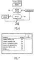
- Figure 6 is a flowchart that describes the steps in conditioning the present invention and its operation with the features that are displayed on the REGIONS SETUP SCREEN of Figure 5.
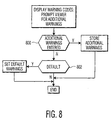
- Figure 7 shows a WARNINGS SET UP SCREEN useful in practicing the present invention.
- Figure 8 is a flowchart that describes the steps in conditioning the present invention and its operation with the features that are displayed on the WARNINGS SETUP SCREEN of Figure 7.
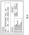
- Figure 9 represents typical information displayed by the ADVANCED SETUP SCREEN of Figure 3, the REGIONS SETUP SCREEN of Figure 5 and the WARNINGS SETUP SCREEN of Figure 7 that is associated with the region selected for warnings displays.
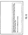
- Figure 10 is an example of a screen display of a warning.
- NWR SAME National Weather Radio Specific Area Message Encoding
- a SAME receiver is included in a geographically specific signal communication receiver constructed in accordance with the present invention to provide this geographically specific signal communication receiver with the capability of receiving and processing NWR SAME warning signal transmissions from which only those warning signals applicable to the region or regions of interest (i.e., the region in which the geographically specific signal communication receiver is located or a nearby region) are selected and conducted to a display unit to display the warnings.
- a geographically specific signal communication receiver constructed in accordance with the present invention, includes first receiving means for receiving a warning signal having information relating to a condition in a geographically specific region and a code component associated with the geographically specific region.
- Such means include, for the embodiment of the invention illustrated by Figure 1, an antenna 10 that can pick up both the warning signal and a television program signal having a video information component and an audio information component.
- Separate antennae one for receiving only the warning signal and one for receiving only the television program signal, can be used as an alternative to a single antenna that receives both signals.
- SAME MODULE 12 includes a SAME RECEIVER 14 that receives and demodulates the warning signal and creates tone signals representative of the information contained in the warning signal.
- the tone signals are conducted to a TONE TO DATA CONVERTER 16 that converts the tone signals to data signals, typically in binary form, that are conducted to a SECONDARY MICROPROCESSOR 18.
- SECONDARY MICROPROCESSOR 18 conducts the output data signals from TONE TO DATA CONVERTER 16 to a MAIN MICROPROCESSOR 20, the function of which will be explained below. Also included in the SAME MODULE 12 illustrated in Figure 1 is a MEMORY 20 that supports SECONDARY MICROPROCESSOR 18 in the same manner that other memory circuits support other microprocessors.
- a BACKUP POWER SUPPLY 22 provides power to SAME MODULE 12, namely to all the units in the SAME MODULE.
- BACKUP POWER SUPPLY 22 also provides power to other units in the receiver illustrated in Figure 1 in the event of a power failure, namely MAIN MICROPROCESSOR 20, a NON-VOLATILE MEMORY/DATABASE 24, a BUZZER 26, and a TUNER 28 each of which will be considered in greater detail below.
- a geographically specific signal communication receiver constructed in accordance with the present invention, also includes means for storing code information associated with a geographic region of interest and other information related to the region of interest.
- the region of interest can be the region in which the geographically specific signal communication receiver is located (i.e., the region in which the user of this receiver is located) or a nearby region (i.e., the region in which a family member or a friend is located or the location of a business or other residence of interest to the user).
- a geographically specific signal communication receiver, constructed in accordance with the present invention can store more than one code associated with a geographic region of interest and related information.
- Such code storage and information storage means include, for the embodiment of the present invention illustrated by Figure 1, NON-VOLATILE MEMORY/DATABASE 24.
- Figure 9 represents typical information related to the region of interest that is stored by NON-VOLATILE MEMORY/DATABASE 24 and that is displayed by the present invention.
- a given region includes a number of zip code areas.
- the region containing the identified zip code area is, in turn, identified by NON-VOLATILE MEMORY/DATABASE 24.
- the Figure 1 geographically specific signal communication receiver further includes means for comparing the stored code information and the code component of the warning signal.
- Such means for the embodiment of the present invention illustrated in Figure 1, are included in MAIN MICROPROCESSOR 20.
- MAIN MICROPROCESSOR 20 develops a control signal
- warning signals other than the one or more that might be of interest are conducted to MAIN MICROPROCESSOR 20 where all but the one or more of interest are eliminated or discarded because of a lack of a match with the stored code or codes.
- selection of the warning signal information of interest i.e., comparison of the codes carried by the warning signals with the stored code
- SECONDARY MICROPORCESSOR 18 scans all incoming warnings and only the one or ones of interest are conducted to MAIN MICROPROCESSOR 20.
- MAIN MICROPROCESSOR 20 also serves to control the nature of the warning signal information that is to be conducted to the MAIN MICROPROCESSOR 20 by SECONDARY MICROPOROCESSOR 18.
- MAIN MICROPROCESSOR 20 can program SECONDARY MICROPROCESSOR 18 to conduct, for example, only warning information about tornadoes.
- a geographically specific signal communication receiver constructed in accordance with the present invention, further includes second receiving means for receiving the warning signal and a television program signal having a video information component and an audio information component, conducting the video information component of the television program signal to a video display and the audio information component of the television program signal to a speaker, and selectively conducting, in response to the control signal developed by MAIN MICROPROCESSOR 20 , the information relating to a condition in the geographically specific region of the warning signal to the video display.
- Such means include, for the embodiment of the invention illustrated in Figure 1, a TUNER 28 that receives both the warning signal and the television program signal from antenna 10.
- TUNER 28 is designed to be frequency selective in passing both the warning signal and the video information component of the television program signal to a VIDEO PROCESSOR 30 and the audio information component of the television program signal to an AUDIO PROCESSOR 32.
- VIDEO PROCESSOR 30 serves to pass the video information component of the television program signal to a VIDEO DISPLAY 34 in the usual way where the video information component of the television program signal is displayed in the usual manner.
- AUDIO PROCESSOR 32 serves to pass the audio information component of the television program signal to a SPEAKER 36 in the usual way where the audio information component of the television program signal is broadcast in the usual manner.
- VIDEO PROCESSOR 30 In addition to processing the video information component of the television program signal, VIDEO PROCESSOR 30, in accordance with the present invention, serves two important functions in connection with the warning signal. First, VIDEO PROCESSOR 30, in response to the control signal developed by MAIN MICROPROCESSOR 20 when the code information included in the warning signal information is the same as the stored code information, permits passage of the video information of the warning signal to VIDEO DISPLAY 34. Second, VIDEO PROCESSOR 30 determines the manner in which the warning signal information is to be displayed by VIDEO DISPLAY 34, for example a footer, or a split-screen, or interruption of a television program, etc. The signals representative of the particular characters included in a video display of the warning are supplied from an OSD (ON SCREEN DISPLAY) MEMORY 38 that is controlled by MAIN MICROPROCESSOR 20.
- OSD ON SCREEN DISPLAY
- the warning signal can have information relating to a condition in the geographically specific region in audio form as well as video form.
- MAIN MICROPROCESSOR 20 controls AUDIO PROCESSOR 32 to pass the audio information relating to a condition in the geographically specific region of the warning signal to SPEAKER 36.
- a geographically specific signal communication receiver constructed in accordance with the present invention, is arranged to be in an "always ON” or “STANDBY” condition to receive warning signals.
- a digital television receiver is "always ON” monitoring information that is being transmitted continuously. Consequently, digital television receivers are ideally suited for the present invention.
- FIG. 2 which shows a BASIC SETUP SCREEN
- the user enters the zip code corresponding to the region of interest for which warnings are to be received and displayed.
- the zip code and other information entered in this screen, and other screens described below is entered by using a remote control unit.
- the user activates "YES” to be alerted for warnings.
- the user will activate "ADVANCED SETUP” to condition or customize the geographically specific signal communication receiver and its operation with certain features that are described below.
- Figure 3 shows an ADVANCED SETUP SCREEN used to condition the geographically specific signal communication receiver and its operation with certain features
- Figure 4 is a flowchart that describes the steps in conditioning the geographically specific signal communication receiver and its operation with the features that are displayed on the ADVANCED SETUP SCREEN.
- the user activates "YES” or “NO” for the first three entries on the ADVANCE SETUP SCREEN of Figure 3 depending on whether the three features are or are not desired.
- First is the option of using or not using BUZZER 26 as shown by step 400 BUZZER ENABLED in Figure 4.
- the next option is to silence BUZZER 26 for a period of time, such as twelve hours, once a warning is acknowledged, so that the user is not bothered constantly by warnings that are transmitted repeatedly.
- the warnings are not disabled permanently should the user forget that BUZZER 26 has been disabled.
- the suppress option is applicable only when BUZZER 26 is in use.
- the third option as shown by step 404 RESET ON-SCREEN MESSAGE, is to display or not display the warning message on DISPLAY 34.
- the next option on the ADVANCED SETUP SCREEN is to enter the television channel on which the user wishes to display the warnings.
- the user typically would enter the local weather channel or a news channel in this field.
- the geographically specific signal communication receiver automatically tunes to this channel upon reception of a warning for a region of interest to the user.
- the remaining entries on the ADVANCED SETUP SCREEN display include information derived from NON-VOLATILE MEMORY/DATABASE 24 when the zip code is entered in the Figure 2 BASIC SETUP SCREEN display. Examples of such information are shown in Figure 9.
- WEATHER FREQUENCY ENTERED the user can set the Weather Radio Frequency.
- step 410 ADDITIONAL WARNINGS the user can enter additional regions of interest.
- step 412 ADDITIONAL WARNINGS the user can enter additional types of warnings.
- Figure 5 shows a REGIONS SETUP SCREEN used to enter the region or regions of interest
- Figure 6 is a flowchart that describes the steps in conditioning the geographically specific signal communication receiver and its operation with the region or regions of interest that are displayed on the REGIONS SETUP SCREEN.
- the identification of a region is derived from NON-VOLATILE MEMORY/DATABASE 24 when the zip code is entered in the Figure 2 BASIC SETUP SCREEN display. Again, such information is shown in Figure 9.
- REGIONS ENTERED the user has the option of storing all the regions of interest or proceeding to step 602 DEFAULT and eliminate those regions that are not of interest.
- Figure 7 shows a WARNINGS SETUP SCREEN used to enter the warning or warnings of interest
- Figure 8 is a flowchart that describes the steps in conditioning the geographically specific signal communication receiver and its operation with the warning or warnings of interest that are displayed on the WARNINGS SETUP SCREEN.
- the identification of a warning is derived from NON-VOLATILE MEMORY/DATABASE 24 when the zip code is entered in the Figure 2 BASIC SETUP SCREEN display. Again, such information is shown in Figure 9.
- step 800 ADDITIONAL WARNINGS ENTERED
- the user has the option of storing all the warnings of interest or proceeding to step 602 DEFAULT and eliminate those warnings that are not of interest.
- Figure 9 represents typical information in NON-VOLATILE MEMORY/DATABASE 24 that corresponds to the zip code that has been entered in the Figure 2 BASIC SETUP SCREEN display. Once the zip code has been entered, this information is provided to the Figure 3 ADVANCED SETUP SCREEN, the Figure 7 REGIONS SETUP SCREEN, and the Figure 7 WARNINGS SETUP SCREEN.
- Figure 10 is an example of a screen display of a warning.
- the warning is displayed as a footer.
Abstract
Description
- The present invention relates, in general, to broadcasting warnings such as weather conditions and, in particular, to a warning system receiver for receiving warnings pertinent to the geographic area in which the warning system receiver is located.
- Several warning methods for alerting populations to weather, emergencies and civil disasters are in use at the present time. Shortcomings and deficiencies of those considered below are indicated.
- Television stations superimpose messages on normal programming or interrupt normal programming to advise their viewers of severe weather conditions. One major deficiency of this warning method is that the region of coverage of the typical local television station (i.e., the region over which the signals transmitted by the local television station are received) is so extensive that the severe weather condition warnings are received in areas within the region of coverage that are not exposed to and will not be affected by the severe weather conditions being reported by the local television station. At best, this is a nuisance to those individuals who hear the alerts but are not, and will not be, affected by the severe weather conditions being reported. Also, this warning method requires that the television receivers be turned on, actively watched, and tuned to a local television station that is broadcasting the severe weather condition warning for the warning to be received and viewed.
- Another example of a warning system currently in use many communities to warn residents of emergencies is a controlled siren, commonly referred to as a civil defense or air raid siren. Such systems are susceptible to mechanical breakdowns and must be taken out of service periodically for routine maintenance. Also, such systems are ineffective to give warnings to those located out of range of the sirens.
- Yet another example of a warning method currently in use in many communities is police and fire departments patrolling the streets and announcing warnings or emergencies over loudspeakers. This method is ineffective when the warning message from the loudspeaker is not heard by those located out of range of the loudspeaker or the warning message is drowned out by weather noise or interfering noise levels in the residences where the warnings are intended to be received by individuals situated in the residences.
- In a special purpose warning system, currently in use by the National Weather Service, continuing weather bulletins are broadcast on a VHF frequency from transmitters of the National Weather Service. Whenever severe weather threatens, an alert is broadcast that triggers an audible alarm in special receivers, such as the weather radio units available from Tandy Corporation. Because the coverage areas of the broadcast stations usually are quite large (i.e., a National Weather Service facility can cover and be responsible for as many as ten to twenty counties), it is possible, as with the broadcasting of severe weather condition warnings by local television stations, to receive alerts on a receiver in an area to which the alerts have no actual significance. Again, at best, this is a nuisance to those individuals who hear the alerts but are not, and will not be, affected by the severe weather conditions being reported. Additionally, when an alert is triggered in such a receiver, it must be muted manually by the user because the system does not have a broadcast "all clear" signal.
- U.S. 5,121,430 describes and illustrates a system designed to overcome the shortcomings identified above of the special purpose warning system described above. The system described in U.S. 5,121,430, however, requires extra, specially designed equipment dedicated to the single purpose of receiving and processing the transmitted warning signals.
- It is an objective of the present invention to provide a new an improved signal communication receiver for receiving warnings of conditions in the region in which the receiver is located.
- It is another objective of the present invention to provide a new and improved signal communication receiver that is geographically specific in receiving warnings of conditions in the region in which the receiver is located.
- A geographically specific signal communication receiver, constructed in accordance with the present invention, includes first receiving means for receiving a warning signal having information relating to a condition in a geographically specific region and a code component associated with the geographically specific region. This geographically specific signal communication receiver also includes means for storing code information associated with a geographic region of interest, means for comparing the stored code information and the code component of the warning signal and means for developing a control signal when the stored code information and the code component of the warning signal are the same. A geographically specific signal communication receiver, constructed in accordance with the present invention, further includes second receiving means for receiving the warning signal and a television program signal having a video information component and an audio information component, conducting the video information component of the television program signal to a video display and the audio information component of the television program signal to a speaker, and selectively conducting, in response to the control signal, the information relating to a condition in the geographically specific region of the warning signal to the video display.
- Although the present invention will be described in connection with the transmission and reception of severe weather condition reports issued by the National Weather Service, it will be apparent that the present invention has broader application and can be used to receive and display other types of messages or warnings that are transmitted with codes associated with geographic regions.
- Figure 1 is a block diagram of a geographically specific signal communication receiver, constructed in accordance with the present invention.
- Figure 2 shows a BASIC SETUP SCREEN useful in practicing the present invention.
- Figure 3 shows an ADVANCED SETUP SCREEN useful in practicing the present invention.
- Figure 4 is a flowchart that describes the steps in conditioning the present invention and its operation with the features that are displayed on the ADVANCED SETUP SCREEN of Figure 3.
- Figure 5 shows a REGIONS SETUP SCREEN useful in practicing the present invention.
- Figure 6 is a flowchart that describes the steps in conditioning the present invention and its operation with the features that are displayed on the REGIONS SETUP SCREEN of Figure 5.
- Figure 7 shows a WARNINGS SET UP SCREEN useful in practicing the present invention.
- Figure 8 is a flowchart that describes the steps in conditioning the present invention and its operation with the features that are displayed on the WARNINGS SETUP SCREEN of Figure 7.
- Figure 9 represents typical information displayed by the ADVANCED SETUP SCREEN of Figure 3, the REGIONS SETUP SCREEN of Figure 5 and the WARNINGS SETUP SCREEN of Figure 7 that is associated with the region selected for warnings displays.
- Figure 10 is an example of a screen display of a warning.
- Starting in 1985, the National Weather Service began experimenting with the insertion of special digital codes at the beginning and the end of messages about a life or property-threatening event. The intent was to ultimately transmit a code with the initial broadcast of National Weather Radio messages. This system evolved into what is known today as National Weather Radio Specific Area Message Encoding (NWR SAME). The technical specifications of NWR SAME have been published and widely circulated. As indicated by Figure 1, a SAME receiver is included in a geographically specific signal communication receiver constructed in accordance with the present invention to provide this geographically specific signal communication receiver with the capability of receiving and processing NWR SAME warning signal transmissions from which only those warning signals applicable to the region or regions of interest (i.e., the region in which the geographically specific signal communication receiver is located or a nearby region) are selected and conducted to a display unit to display the warnings.
- Referring to Figure 1, a geographically specific signal communication receiver, constructed in accordance with the present invention, includes first receiving means for receiving a warning signal having information relating to a condition in a geographically specific region and a code component associated with the geographically specific region. Such means include, for the embodiment of the invention illustrated by Figure 1, an
antenna 10 that can pick up both the warning signal and a television program signal having a video information component and an audio information component. Separate antennae, one for receiving only the warning signal and one for receiving only the television program signal, can be used as an alternative to a single antenna that receives both signals. - The warning signal picked up by
antenna 10 is conducted to and received by aSAME MODULE 12 as illustrated by Figure 1.SAME MODULE 12 includes aSAME RECEIVER 14 that receives and demodulates the warning signal and creates tone signals representative of the information contained in the warning signal. The tone signals are conducted to a TONE TODATA CONVERTER 16 that converts the tone signals to data signals, typically in binary form, that are conducted to aSECONDARY MICROPROCESSOR 18. - SECONDARY
MICROPROCESSOR 18 conducts the output data signals from TONE TO DATA CONVERTER 16 to aMAIN MICROPROCESSOR 20, the function of which will be explained below. Also included in theSAME MODULE 12 illustrated in Figure 1 is aMEMORY 20 that supports SECONDARYMICROPROCESSOR 18 in the same manner that other memory circuits support other microprocessors. - In the event of a power failure, a BACKUP POWER SUPPLY 22 provides power to
SAME MODULE 12, namely to all the units in the SAME MODULE. BACKUP POWER SUPPLY 22 also provides power to other units in the receiver illustrated in Figure 1 in the event of a power failure, namelyMAIN MICROPROCESSOR 20, a NON-VOLATILE MEMORY/DATABASE 24, aBUZZER 26, and aTUNER 28 each of which will be considered in greater detail below. - A geographically specific signal communication receiver, constructed in accordance with the present invention, also includes means for storing code information associated with a geographic region of interest and other information related to the region of interest. The region of interest can be the region in which the geographically specific signal communication receiver is located (i.e., the region in which the user of this receiver is located) or a nearby region (i.e., the region in which a family member or a friend is located or the location of a business or other residence of interest to the user). A geographically specific signal communication receiver, constructed in accordance with the present invention, can store more than one code associated with a geographic region of interest and related information. Such code storage and information storage means include, for the embodiment of the present invention illustrated by Figure 1, NON-VOLATILE MEMORY/
DATABASE 24. Figure 9 represents typical information related to the region of interest that is stored by NON-VOLATILE MEMORY/DATABASE 24 and that is displayed by the present invention. A given region includes a number of zip code areas. When a zip code of interest is identified by the user, the region containing the identified zip code area is, in turn, identified by NON-VOLATILE MEMORY/DATABASE 24. - The Figure 1 geographically specific signal communication receiver further includes means for comparing the stored code information and the code component of the warning signal. Such means, for the embodiment of the present invention illustrated in Figure 1, are included in MAIN MICROPROCESSOR 20. When the stored code information (i.e., the code associated with the region identified by NON-VOLATILE MEMORY/DATABASE 24) and the code component of the warning signal are the same, MAIN
MICROPROCESSOR 20 develops a control signal - It should be noted that, for the embodiment of the present invention illustrated by Figure 1, the information contained in warning signals other than the one or more that might be of interest (i.e., the region or regions corresponding to the code stored in NON-VOLATILE MEMORY/DATABASE 26) are conducted to
MAIN MICROPROCESSOR 20 where all but the one or more of interest are eliminated or discarded because of a lack of a match with the stored code or codes. It will be understood that such selection of the warning signal information of interest (i.e., comparison of the codes carried by the warning signals with the stored code) can be carried out earlier in the signal processing of the warning signal, for example inSECONDARY MICROPROCESSOR 18. In such an arrangement,SECONDARY MICROPORCESSOR 18 scans all incoming warnings and only the one or ones of interest are conducted toMAIN MICROPROCESSOR 20. -
MAIN MICROPROCESSOR 20 also serves to control the nature of the warning signal information that is to be conducted to theMAIN MICROPROCESSOR 20 bySECONDARY MICROPOROCESSOR 18.MAIN MICROPROCESSOR 20 can programSECONDARY MICROPROCESSOR 18 to conduct, for example, only warning information about tornadoes. - A geographically specific signal communication receiver, constructed in accordance with the present invention, further includes second receiving means for receiving the warning signal and a television program signal having a video information component and an audio information component, conducting the video information component of the television program signal to a video display and the audio information component of the television program signal to a speaker, and selectively conducting, in response to the control signal developed by
MAIN MICROPROCESSOR 20, the information relating to a condition in the geographically specific region of the warning signal to the video display. Such means include, for the embodiment of the invention illustrated in Figure 1, aTUNER 28 that receives both the warning signal and the television program signal fromantenna 10.TUNER 28 is designed to be frequency selective in passing both the warning signal and the video information component of the television program signal to aVIDEO PROCESSOR 30 and the audio information component of the television program signal to anAUDIO PROCESSOR 32. -
VIDEO PROCESSOR 30 serves to pass the video information component of the television program signal to aVIDEO DISPLAY 34 in the usual way where the video information component of the television program signal is displayed in the usual manner.AUDIO PROCESSOR 32 serves to pass the audio information component of the television program signal to aSPEAKER 36 in the usual way where the audio information component of the television program signal is broadcast in the usual manner. - In addition to processing the video information component of the television program signal,
VIDEO PROCESSOR 30, in accordance with the present invention, serves two important functions in connection with the warning signal. First,VIDEO PROCESSOR 30, in response to the control signal developed byMAIN MICROPROCESSOR 20 when the code information included in the warning signal information is the same as the stored code information, permits passage of the video information of the warning signal toVIDEO DISPLAY 34. Second,VIDEO PROCESSOR 30 determines the manner in which the warning signal information is to be displayed byVIDEO DISPLAY 34, for example a footer, or a split-screen, or interruption of a television program, etc. The signals representative of the particular characters included in a video display of the warning are supplied from an OSD (ON SCREEN DISPLAY)MEMORY 38 that is controlled byMAIN MICROPROCESSOR 20. - The control signal developed by
MAIN MICROPROCESSOR 20 when the code information included in the warning signal information matches the stored code information, along with an input fromSECONDARY MICROPROCESSOR 18, serve to actuateBUZZER 26 to provide an audible alarm that warning information, specific to the region or regions of interest has been received and the user can then turn his or her attention toVIDEO DISPLAY 34 to view the warning. - It should be noted that the warning signal can have information relating to a condition in the geographically specific region in audio form as well as video form. In such a case,
MAIN MICROPROCESSOR 20, controlsAUDIO PROCESSOR 32 to pass the audio information relating to a condition in the geographically specific region of the warning signal toSPEAKER 36. - Preferably, a geographically specific signal communication receiver, constructed in accordance with the present invention, is arranged to be in an "always ON" or "STANDBY" condition to receive warning signals. Typically, a digital television receiver is "always ON" monitoring information that is being transmitted continuously. Consequently, digital television receivers are ideally suited for the present invention.
- Referring to Figure 2, which shows a BASIC SETUP SCREEN, the user enters the zip code corresponding to the region of interest for which warnings are to be received and displayed. Preferably, the zip code and other information entered in this screen, and other screens described below, is entered by using a remote control unit. After entering the zip code, the user activates "YES" to be alerted for warnings. Then the user will activate "ADVANCED SETUP" to condition or customize the geographically specific signal communication receiver and its operation with certain features that are described below.
- Figure 3 shows an ADVANCED SETUP SCREEN used to condition the geographically specific signal communication receiver and its operation with certain features and Figure 4 is a flowchart that describes the steps in conditioning the geographically specific signal communication receiver and its operation with the features that are displayed on the ADVANCED SETUP SCREEN. The user activates "YES" or "NO" for the first three entries on the ADVANCE SETUP SCREEN of Figure 3 depending on whether the three features are or are not desired. First is the option of using or not using
BUZZER 26 as shown bystep 400 BUZZER ENABLED in Figure 4. The next option, as shown bystep 402 12 HOUR SUPPRESS, is to silenceBUZZER 26 for a period of time, such as twelve hours, once a warning is acknowledged, so that the user is not bothered constantly by warnings that are transmitted repeatedly. The warnings are not disabled permanently should the user forget thatBUZZER 26 has been disabled. The suppress option is applicable only whenBUZZER 26 is in use. The third option, as shown bystep 404 RESET ON-SCREEN MESSAGE, is to display or not display the warning message onDISPLAY 34. - The next option on the ADVANCED SETUP SCREEN, as shown by
step 406 TUNE CHANNEL ENTERED, is to enter the television channel on which the user wishes to display the warnings. The user typically would enter the local weather channel or a news channel in this field. The geographically specific signal communication receiver automatically tunes to this channel upon reception of a warning for a region of interest to the user. - The remaining entries on the ADVANCED SETUP SCREEN display, made at the option of the user, include information derived from NON-VOLATILE MEMORY/
DATABASE 24 when the zip code is entered in the Figure 2 BASIC SETUP SCREEN display. Examples of such information are shown in Figure 9. As shown bystep 408 WEATHER FREQUENCY ENTERED, the user can set the Weather Radio Frequency. As shown bystep 410 ADDITIONAL WARNINGS, the user can enter additional regions of interest. As shown bystep 412 ADDITIONAL WARNINGS, the user can enter additional types of warnings. - Figure 5 shows a REGIONS SETUP SCREEN used to enter the region or regions of interest and Figure 6 is a flowchart that describes the steps in conditioning the geographically specific signal communication receiver and its operation with the region or regions of interest that are displayed on the REGIONS SETUP SCREEN. The identification of a region is derived from NON-VOLATILE MEMORY/
DATABASE 24 when the zip code is entered in the Figure 2 BASIC SETUP SCREEN display. Again, such information is shown in Figure 9. Starting withstep 600 REGIONS ENTERED, the user has the option of storing all the regions of interest or proceeding to step 602 DEFAULT and eliminate those regions that are not of interest. - Figure 7 shows a WARNINGS SETUP SCREEN used to enter the warning or warnings of interest and Figure 8 is a flowchart that describes the steps in conditioning the geographically specific signal communication receiver and its operation with the warning or warnings of interest that are displayed on the WARNINGS SETUP SCREEN. The identification of a warning is derived from NON-VOLATILE MEMORY/
DATABASE 24 when the zip code is entered in the Figure 2 BASIC SETUP SCREEN display. Again, such information is shown in Figure 9. Starting withstep 800 ADDITIONAL WARNINGS ENTERED, the user has the option of storing all the warnings of interest or proceeding to step 602 DEFAULT and eliminate those warnings that are not of interest. - Figure 9 represents typical information in NON-VOLATILE MEMORY/
DATABASE 24 that corresponds to the zip code that has been entered in the Figure 2 BASIC SETUP SCREEN display. Once the zip code has been entered, this information is provided to the Figure 3 ADVANCED SETUP SCREEN, the Figure 7 REGIONS SETUP SCREEN, and the Figure 7 WARNINGS SETUP SCREEN. - Figure 10 is an example of a screen display of a warning. In this example, the warning is displayed as a footer.
- While in the foregoing there have been described preferred embodiments of the present invention, it should be understood by those skilled in the art that various modifications and changes can be made without departing from the true spirit and scope of the present invention.
Claims (13)
- A geographically specific signal communication receiver comprising:first receiving means for receiving a warning signal having:(a) information relating to a condition in a geographically specific region, and(b) a code component associated with the geographically specific region;means for storing code information associated with a geographic region of interest;means for comparing the stored code information and the code component of the warning signal;means for developing a control signal when the stored code information and the code component of the warning signal are the same; andsecond receiving means for:(a) receiving the warning signal and a television program signal having a video information component and an audio information component,(b) conducting the video information component of the television program signal to a video display and the audio information component of the television program signal to a speaker, and(c) selectively conducting, in response to the control signal, the information relating to a condition in the geographically specific region of the warning signal to the video display.
- A geographically specific signal communication receiver comprising:an antenna for receiving:(a) a television program signal having a video information component and an audio information component; and(b) a warning signal having:(1) information relating to a condition in a geographically specific region, and(2) a code component associated with the geographically specific region;first receiving means for receiving the warning signal;means for storing code information associated with a geographic region of interest;means for comparing the stored code information and the code component of the warning signal;means for developing a control signal when the stored code information and the code component of the warning signal are the same;second receiving means for:(a) receiving the warning signal and the television program signal,(b) conducting the video information component of the television program signal to a video display and the audio information component of the television program signal to a speaker, and(c) selectively conducting, in response to the control signal, the information relating to a condition in the geographically specific region of the warning signal to the video display;a video display for displaying the video content of the television program signal and the information relating to a condition in a geographically specific region of the warning signal; anda speaker for broadcasting the audio content of the television program signal.
- A geographically specific signal communications receiver according to claim 1 wherein:(a) said first receiving means include:(1) an antenna for receiving the warning signal, and(2) a Specific Area Message Encoding module responsive to the warning signal for developing data signals representative of:(i) the information of the warning signal relating to a condition in a geographically specific region, and(ii) the code component of the warning signal associated with the geographically specific region,(b) said comparing means include a microprocessor responsive to the stored code information and the data signals representative of the code component of the warning signal for developing the control signal when the stored code information and the code component of the warning signal are the same.
- A geographically specific signal communications receiver according to claim 3 wherein said microprocessor controls said Specific Area Message Encoding module to develop data signals representative of a selected condition.
- A geographically specific signal communications receiver according to claim 3 wherein said second receiving means include:(a) a tuner for receiving the warning signal and the television program signal,(b) a video processor for:(1) conducting the video information component of the television program signal to a video display, and(2) conducting the warning signal to a video display in response to the control signal developed by said microprocessor, and(c) an audio processor for conducting the audio information component of the television program signal to a speaker.
- A geographically specific signal communications receiver according to claim 5 wherein said video processor also determines the manner in which the warning signal information is displayed by a video display.
- A geographically specific signal communications receiver according to claim 5 further including audible alarm means responsive to said Specific Area Message Encoding module and said microprocessor for developing an audible alarm when a warning signal has been received.
- A geographically specific signal communications receiver according to claim 5 wherein the warning signal also includes information relating to a condition in a geographically specific region in audio form and said audio processor conducts the audio warning signal to a speaker in response to the control signal developed by said microprocessor.
- A geographically specific signal communications receiver according to claim 2 wherein the code component of the warning signal and the stored code information are a zip code.
- A geographically specific signal communications receiver according to claim 2 wherein a plurality of zip codes are stored as code information and the code component of the warning signal is a zip code.
- A method for setting a geographically specific signal communications receiver to receive and display warning signals comprising the steps:entering in said receiver a code corresponding to a geographic region of interest for which warning signals are to be received and displayed;conditioning an audible alarm in said receiver that indicates reception of a warning signal;conditioning a video display in said receiver to display a warning signal;setting said receiver to a television channel on which a warning signal is to be displayed;setting said receiver to display a selected type of warning signal; andsetting said receiver with a selected format for displaying a warning signal.
- The method of claim 11 wherein the code is a zip code.
- The method of claim 12 wherein the format for displaying a warning signal is selected from the group consisting of a footer display, a split-screen display, and an interruption of a television program.
Applications Claiming Priority (2)
| Application Number | Priority Date | Filing Date | Title |
|---|---|---|---|
| US541016 | 2000-03-31 | ||
| US09/541,016 US7114169B1 (en) | 2000-03-31 | 2000-03-31 | Geographically specific signal communications receiver |
Publications (3)
| Publication Number | Publication Date |
|---|---|
| EP1143394A2 true EP1143394A2 (en) | 2001-10-10 |
| EP1143394A3 EP1143394A3 (en) | 2002-08-14 |
| EP1143394B1 EP1143394B1 (en) | 2005-08-24 |
Family
ID=24157855
Family Applications (1)
| Application Number | Title | Priority Date | Filing Date |
|---|---|---|---|
| EP01104589A Expired - Lifetime EP1143394B1 (en) | 2000-03-31 | 2001-03-06 | Geographically specific signal communications receiver |
Country Status (5)
| Country | Link |
|---|---|
| US (1) | US7114169B1 (en) |
| EP (1) | EP1143394B1 (en) |
| JP (1) | JP2001339658A (en) |
| CN (1) | CN1191685C (en) |
| DE (1) | DE60112833T2 (en) |
Cited By (8)
| Publication number | Priority date | Publication date | Assignee | Title |
|---|---|---|---|---|
| WO2004047041A1 (en) * | 2002-11-15 | 2004-06-03 | Thomson Licensing S.A. | Method for detecting whether an apparatus having an emergency alert function has been relocated |
| EP1550305A2 (en) * | 2002-06-27 | 2005-07-06 | Thomson Licensing S.A. | Apparatus and method for providing user selectable alert modes for a television signal receiver |
| EP1597830A2 (en) * | 2002-11-15 | 2005-11-23 | Thomson Licensing | Methods for controlling apparatuses having an emergency alert function |
| EP1609309A2 (en) * | 2003-03-31 | 2005-12-28 | Thomson Licensing S.A. | Methods for controlling apparatuses having an emergency alert function |
| CH696048A5 (en) * | 2002-07-19 | 2006-11-30 | Barix Ag | Warning system. |
| WO2007001280A1 (en) * | 2005-06-21 | 2007-01-04 | Thomson Licensing | Apparatus having an emergency alert function capable of detecting redundant notifications |
| WO2007001269A1 (en) * | 2005-06-21 | 2007-01-04 | Thomson Licensing | Apparatus having an emergency alert function that facilitates location selection |
| EP2000999A1 (en) * | 2007-06-09 | 2008-12-10 | e* Message Wireless Information Services GmbH | System and method for transmitting a warning message via a wireless network |
Families Citing this family (24)
| Publication number | Priority date | Publication date | Assignee | Title |
|---|---|---|---|---|
| JP2003269969A (en) | 2002-03-13 | 2003-09-25 | Sony Corp | Navigation device, and spot information display method and program |
| US20050229206A1 (en) * | 2002-05-10 | 2005-10-13 | Pugel Michael A | Television signal receiver capable of receiving emergency alert signals |
| EP1530874A4 (en) * | 2002-05-10 | 2005-06-22 | Thomson Licensing Sa | Remote control device for television signal receiver capable of receiving emergency alert signals |
| WO2004045211A1 (en) * | 2002-11-12 | 2004-05-27 | Thomson Licensing S.A. | Conversion of alert messages for dissemination in a program distribution network |
| CN100352267C (en) * | 2002-11-15 | 2007-11-28 | 汤姆森许可贸易公司 | Apparatus and method for receiving emergency alert signals |
| US8050281B2 (en) | 2003-01-31 | 2011-11-01 | Qwest Communications International Inc. | Alert gateway, systems and methods |
| US8490129B2 (en) * | 2003-01-31 | 2013-07-16 | Qwest Communications International Inc. | Methods, systems and apparatus for selectively distributing urgent public information |
| US10142023B2 (en) | 2003-01-31 | 2018-11-27 | Centurylink Intellectual Property Llc | Antenna system and methods for wireless optical network termination |
| US20060130100A1 (en) * | 2004-10-12 | 2006-06-15 | Pentland Joseph D | Methods and apparatus for remotely displaying and distributing advertising and emergency information |
| US7358855B1 (en) * | 2005-06-06 | 2008-04-15 | Maxillis, Ltd. | Local area warning system (laws) |
| KR20080016834A (en) * | 2005-06-21 | 2008-02-22 | 톰슨 라이센싱 | Apparatus and method for interfacing different emergency alert systems |
| US8566887B2 (en) | 2005-12-09 | 2013-10-22 | Time Warner Cable Enterprises Llc | Caption data delivery apparatus and methods |
| US7592912B2 (en) | 2005-12-09 | 2009-09-22 | Time Warner Cable Inc. | Emergency alert data delivery apparatus and methods |
| US8362895B2 (en) * | 2007-02-22 | 2013-01-29 | Honeywell International Inc. | Systems and methods of information distribution |
| US8959545B2 (en) * | 2008-02-29 | 2015-02-17 | Sony Corporation | Reverse 911 using TV |
| US8095610B2 (en) | 2008-03-28 | 2012-01-10 | Time Warner Cable Inc. | Methods and apparatus for centralized and decentralized emergency alert messaging |
| US8813121B2 (en) * | 2008-12-02 | 2014-08-19 | At&T Intellectual Property I, L.P. | Delaying emergency alert system messages |
| DE102009038692A1 (en) * | 2009-08-24 | 2011-03-17 | Swissphone Telecom Ag | Terminal for a telecommunication network and method for operating such a terminal |
| US9392641B2 (en) | 2012-07-05 | 2016-07-12 | Centurylink Intellectual Property Llc | Multi-service provider wireless access point |
| US9497800B2 (en) | 2012-07-05 | 2016-11-15 | Centurylink Intellectual Property Llc | Multi-service provider wireless access point |
| KR102163893B1 (en) * | 2013-10-02 | 2020-10-12 | 엘지전자 주식회사 | Image display device and control method thereof |
| US9472091B2 (en) | 2013-10-21 | 2016-10-18 | Time Warner Cable Enterprises Llc | Systems and methods for providing emergency alerts |
| CN105833001B (en) * | 2016-05-11 | 2017-10-24 | 鲁南制药集团股份有限公司 | Purposes of the SHENQI JIANGTANG KELI in diabetic cardiomyopathy medicine is prepared |
| US10965899B1 (en) * | 2017-04-17 | 2021-03-30 | Alarm.Com Incorporated | System and method for integration of a television into a connected-home monitoring system |
Citations (2)
| Publication number | Priority date | Publication date | Assignee | Title |
|---|---|---|---|---|
| US5121430A (en) * | 1991-02-19 | 1992-06-09 | Ganzer Larry R | Storm alert for emergencies |
| US5701161A (en) * | 1994-12-14 | 1997-12-23 | Williams; Mark C. | Method and apparatus for providing real time data on a viewing screen concurrently with any programing in process |
Family Cites Families (16)
| Publication number | Priority date | Publication date | Assignee | Title |
|---|---|---|---|---|
| US3993955A (en) * | 1975-04-25 | 1976-11-23 | Tocom, Inc. | Method of and apparatus for establishing emergency communications in a two-way cable television system |
| JPH0437318A (en) * | 1990-06-01 | 1992-02-07 | Nec Corp | Radio signal receiver |
| US5565909A (en) * | 1992-08-31 | 1996-10-15 | Television Computer, Inc. | Method of identifying set-top receivers |
| JP3082820B2 (en) * | 1993-11-25 | 2000-08-28 | ソニー株式会社 | Receiving device and digital data reception processing method |
| JPH07336664A (en) * | 1994-06-10 | 1995-12-22 | Sanyo Electric Co Ltd | Pay television set |
| JP3473995B2 (en) * | 1994-08-02 | 2003-12-08 | 株式会社日立製作所 | Emergency information communication system |
| US6583825B1 (en) * | 1994-11-07 | 2003-06-24 | Index Systems, Inc. | Method and apparatus for transmitting and downloading setup information |
| US5848396A (en) * | 1996-04-26 | 1998-12-08 | Freedom Of Information, Inc. | Method and apparatus for determining behavioral profile of a computer user |
| US6052556A (en) * | 1996-09-27 | 2000-04-18 | Sharp Laboratories Of America | Interactivity enhancement apparatus for consumer electronics products |
| JPH10126357A (en) * | 1996-10-18 | 1998-05-15 | Komushisu:Kk | Fm teletext display device |
| US6177931B1 (en) * | 1996-12-19 | 2001-01-23 | Index Systems, Inc. | Systems and methods for displaying and recording control interface with television programs, video, advertising information and program scheduling information |
| JP3720986B2 (en) * | 1997-07-22 | 2005-11-30 | 株式会社東芝 | Digital broadcast receiver |
| EP0912053A1 (en) * | 1997-10-24 | 1999-04-28 | CANAL+ Société Anonyme | Multichannel digital television system |
| US5937329A (en) * | 1997-10-29 | 1999-08-10 | Northern Telecom Limited | System and method for displaying local messages over a satellite television picture |
| US6204761B1 (en) * | 1998-11-13 | 2001-03-20 | Jerome Vanderable | Weather alert system |
| US6177873B1 (en) * | 1999-02-08 | 2001-01-23 | International Business Machines Corporation | Weather warning apparatus and method |
-
2000
- 2000-03-31 US US09/541,016 patent/US7114169B1/en not_active Expired - Fee Related
-
2001
- 2001-03-06 DE DE60112833T patent/DE60112833T2/en not_active Expired - Lifetime
- 2001-03-06 EP EP01104589A patent/EP1143394B1/en not_active Expired - Lifetime
- 2001-03-30 CN CNB01109561XA patent/CN1191685C/en not_active Expired - Fee Related
- 2001-04-02 JP JP2001103943A patent/JP2001339658A/en active Pending
Patent Citations (4)
| Publication number | Priority date | Publication date | Assignee | Title |
|---|---|---|---|---|
| US5121430A (en) * | 1991-02-19 | 1992-06-09 | Ganzer Larry R | Storm alert for emergencies |
| US5121430B1 (en) * | 1991-02-19 | 1998-09-01 | Quad Dimension Inc | Storm alert for emergencies |
| US5121430C2 (en) * | 1991-02-19 | 2002-09-10 | Quad Dimension Inc | Storm alert for emergencies |
| US5701161A (en) * | 1994-12-14 | 1997-12-23 | Williams; Mark C. | Method and apparatus for providing real time data on a viewing screen concurrently with any programing in process |
Cited By (15)
| Publication number | Priority date | Publication date | Assignee | Title |
|---|---|---|---|---|
| EP1550305A2 (en) * | 2002-06-27 | 2005-07-06 | Thomson Licensing S.A. | Apparatus and method for providing user selectable alert modes for a television signal receiver |
| EP1550305A4 (en) * | 2002-06-27 | 2005-10-12 | Thomson Licensing | Apparatus and method for providing user selectable alert modes for a television signal receiver |
| CH696048A5 (en) * | 2002-07-19 | 2006-11-30 | Barix Ag | Warning system. |
| EP1597830A2 (en) * | 2002-11-15 | 2005-11-23 | Thomson Licensing | Methods for controlling apparatuses having an emergency alert function |
| WO2004047041A1 (en) * | 2002-11-15 | 2004-06-03 | Thomson Licensing S.A. | Method for detecting whether an apparatus having an emergency alert function has been relocated |
| EP1597830A4 (en) * | 2002-11-15 | 2007-03-07 | Thomson Licensing | Methods for controlling apparatuses having an emergency alert function |
| US7913274B2 (en) | 2002-11-15 | 2011-03-22 | Thomson Licensing | Method for detecting whether an apparatus having an emergency alert function has been relocated |
| EP1609309A2 (en) * | 2003-03-31 | 2005-12-28 | Thomson Licensing S.A. | Methods for controlling apparatuses having an emergency alert function |
| EP1609309A4 (en) * | 2003-03-31 | 2006-03-29 | Thomson Licensing | Methods for controlling apparatuses having an emergency alert function |
| WO2007001280A1 (en) * | 2005-06-21 | 2007-01-04 | Thomson Licensing | Apparatus having an emergency alert function capable of detecting redundant notifications |
| WO2007001269A1 (en) * | 2005-06-21 | 2007-01-04 | Thomson Licensing | Apparatus having an emergency alert function that facilitates location selection |
| EP2000999A1 (en) * | 2007-06-09 | 2008-12-10 | e* Message Wireless Information Services GmbH | System and method for transmitting a warning message via a wireless network |
| WO2008151975A1 (en) * | 2007-06-09 | 2008-12-18 | E*Message Wireless Information Services Deutschland Gmbh | System and method for transmitting a warning message via a radio network |
| US8213897B2 (en) | 2007-06-09 | 2012-07-03 | E*Message Wireless Information Services Deutschland Gmbh | System and method for transmitting a warning message via a radio network |
| KR101503090B1 (en) * | 2007-06-09 | 2015-03-16 | 이*메시지 와이어리스 인포메이션 서비스즈 도이칠란트 게엠베하 | System and method for transmitting a warning message via a radio network |
Also Published As
| Publication number | Publication date |
|---|---|
| CN1191685C (en) | 2005-03-02 |
| JP2001339658A (en) | 2001-12-07 |
| EP1143394B1 (en) | 2005-08-24 |
| US7114169B1 (en) | 2006-09-26 |
| CN1323104A (en) | 2001-11-21 |
| DE60112833T2 (en) | 2006-03-09 |
| EP1143394A3 (en) | 2002-08-14 |
| DE60112833D1 (en) | 2005-09-29 |
Similar Documents
| Publication | Publication Date | Title |
|---|---|---|
| US7114169B1 (en) | Geographically specific signal communications receiver | |
| US20060005219A1 (en) | Standby television warning system | |
| US20030093789A1 (en) | Systems for monitoring broadcast content and generating notification signals as a function of subscriber profiles and methods of operating the same | |
| US20090141173A1 (en) | Apparatus Having an Emergency Alert Function With Priority Override Feature | |
| KR20050086564A (en) | Weather/disaster alert system using a data network | |
| US20060184962A1 (en) | Methods for controlling apparatuses having an emergency alert function | |
| US20060271952A1 (en) | Apparatus having an emergency alert function with single button control | |
| KR20050074623A (en) | Apparatus and method for receiving emergency alert signals | |
| US20100218209A1 (en) | Apparatus having an emergency alert function that facilitates location selection | |
| EP1597830B1 (en) | Methods for controlling apparatuses having an emergency alert function | |
| US20070066366A1 (en) | Method and system for implementing an emergency alert receiver system in a cellular phone | |
| EP1561337A2 (en) | Apparatus and method for providing alert outputs | |
| KR101253159B1 (en) | Digital broadcast signal and apparatus and method of processing the signal | |
| WO2006065787A2 (en) | Multi-tuner apparatus for providing an emergency alert function | |
| US20090224880A1 (en) | Apparatus and Method for Providing an Emergency Alert Function with Adjustable Volume Control | |
| KR20050075401A (en) | Method for detecting whether an apparatus having an emergency alert function has been relocated | |
| WO2007001280A1 (en) | Apparatus having an emergency alert function capable of detecting redundant notifications | |
| US20060156333A1 (en) | Distance check for television signal receiver having an emergency alert function | |
| WO2004004305A2 (en) | Apparatus and method for providing user selectable alert modes for a television signal receiver | |
| KR20080032077A (en) | Apparatus having an emergency alert function with priority override feature |
Legal Events
| Date | Code | Title | Description |
|---|---|---|---|
| PUAI | Public reference made under article 153(3) epc to a published international application that has entered the european phase |
Free format text: ORIGINAL CODE: 0009012 |
|
| AK | Designated contracting states |
Kind code of ref document: A2 Designated state(s): AT BE CH CY DE DK ES FI FR GB GR IE IT LI LU MC NL PT SE TR |
|
| AX | Request for extension of the european patent |
Free format text: AL;LT;LV;MK;RO;SI |
|
| PUAL | Search report despatched |
Free format text: ORIGINAL CODE: 0009013 |
|
| AK | Designated contracting states |
Kind code of ref document: A3 Designated state(s): AT BE CH CY DE DK ES FI FR GB GR IE IT LI LU MC NL PT SE TR |
|
| AX | Request for extension of the european patent |
Free format text: AL;LT;LV;MK;RO;SI |
|
| RIC1 | Information provided on ipc code assigned before grant |
Free format text: 7G 08B 21/00 A, 7G 08B 25/08 B, 7G 08B 27/00 B |
|
| 17P | Request for examination filed |
Effective date: 20030214 |
|
| AKX | Designation fees paid |
Designated state(s): DE FR GB |
|
| 17Q | First examination report despatched |
Effective date: 20030526 |
|
| GRAP | Despatch of communication of intention to grant a patent |
Free format text: ORIGINAL CODE: EPIDOSNIGR1 |
|
| GRAS | Grant fee paid |
Free format text: ORIGINAL CODE: EPIDOSNIGR3 |
|
| GRAA | (expected) grant |
Free format text: ORIGINAL CODE: 0009210 |
|
| AK | Designated contracting states |
Kind code of ref document: B1 Designated state(s): DE FR GB |
|
| REG | Reference to a national code |
Ref country code: GB Ref legal event code: FG4D |
|
| REF | Corresponds to: |
Ref document number: 60112833 Country of ref document: DE Date of ref document: 20050929 Kind code of ref document: P |
|
| ET | Fr: translation filed | ||
| PLBE | No opposition filed within time limit |
Free format text: ORIGINAL CODE: 0009261 |
|
| STAA | Information on the status of an ep patent application or granted ep patent |
Free format text: STATUS: NO OPPOSITION FILED WITHIN TIME LIMIT |
|
| 26N | No opposition filed |
Effective date: 20060526 |
|
| REG | Reference to a national code |
Ref country code: DE Ref legal event code: R084 Ref document number: 60112833 Country of ref document: DE |
|
| REG | Reference to a national code |
Ref country code: GB Ref legal event code: 746 Effective date: 20130617 |
|
| REG | Reference to a national code |
Ref country code: DE Ref legal event code: R084 Ref document number: 60112833 Country of ref document: DE Effective date: 20130701 |
|
| REG | Reference to a national code |
Ref country code: FR Ref legal event code: PLFP Year of fee payment: 15 |
|
| PGFP | Annual fee paid to national office [announced via postgrant information from national office to epo] |
Ref country code: DE Payment date: 20150305 Year of fee payment: 15 |
|
| PGFP | Annual fee paid to national office [announced via postgrant information from national office to epo] |
Ref country code: FR Payment date: 20150309 Year of fee payment: 15 Ref country code: GB Payment date: 20150304 Year of fee payment: 15 |
|
| REG | Reference to a national code |
Ref country code: DE Ref legal event code: R119 Ref document number: 60112833 Country of ref document: DE |
|
| GBPC | Gb: european patent ceased through non-payment of renewal fee |
Effective date: 20160306 |
|
| REG | Reference to a national code |
Ref country code: FR Ref legal event code: ST Effective date: 20161130 |
|
| PG25 | Lapsed in a contracting state [announced via postgrant information from national office to epo] |
Ref country code: FR Free format text: LAPSE BECAUSE OF NON-PAYMENT OF DUE FEES Effective date: 20160331 Ref country code: GB Free format text: LAPSE BECAUSE OF NON-PAYMENT OF DUE FEES Effective date: 20160306 Ref country code: DE Free format text: LAPSE BECAUSE OF NON-PAYMENT OF DUE FEES Effective date: 20161001 |