EP1143167A2 - Toroidal continuously variable transmission - Google Patents
Toroidal continuously variable transmission Download PDFInfo
- Publication number
- EP1143167A2 EP1143167A2 EP01108420A EP01108420A EP1143167A2 EP 1143167 A2 EP1143167 A2 EP 1143167A2 EP 01108420 A EP01108420 A EP 01108420A EP 01108420 A EP01108420 A EP 01108420A EP 1143167 A2 EP1143167 A2 EP 1143167A2
- Authority
- EP
- European Patent Office
- Prior art keywords
- roller
- input
- output disks
- continuously variable
- power
- Prior art date
- Legal status (The legal status is an assumption and is not a legal conclusion. Google has not performed a legal analysis and makes no representation as to the accuracy of the status listed.)
- Granted
Links
- 230000005540 biological transmission Effects 0.000 title claims description 27
- 238000005461 lubrication Methods 0.000 claims description 36
- 230000006835 compression Effects 0.000 abstract description 2
- 238000007906 compression Methods 0.000 abstract description 2
- 230000007246 mechanism Effects 0.000 description 16
- 230000000694 effects Effects 0.000 description 3
- 238000003780 insertion Methods 0.000 description 3
- 230000037431 insertion Effects 0.000 description 3
- 230000004044 response Effects 0.000 description 3
- 238000003860 storage Methods 0.000 description 3
- 230000006866 deterioration Effects 0.000 description 1
- 238000006073 displacement reaction Methods 0.000 description 1
- 238000004519 manufacturing process Methods 0.000 description 1
- 238000012986 modification Methods 0.000 description 1
- 230000004048 modification Effects 0.000 description 1
- 230000036316 preload Effects 0.000 description 1
- 238000003825 pressing Methods 0.000 description 1
Images



Classifications
-
- F—MECHANICAL ENGINEERING; LIGHTING; HEATING; WEAPONS; BLASTING
- F16—ENGINEERING ELEMENTS AND UNITS; GENERAL MEASURES FOR PRODUCING AND MAINTAINING EFFECTIVE FUNCTIONING OF MACHINES OR INSTALLATIONS; THERMAL INSULATION IN GENERAL
- F16H—GEARING
- F16H57/00—General details of gearing
- F16H57/04—Features relating to lubrication or cooling or heating
- F16H57/042—Guidance of lubricant
- F16H57/0421—Guidance of lubricant on or within the casing, e.g. shields or baffles for collecting lubricant, tubes, pipes, grooves, channels or the like
-
- F—MECHANICAL ENGINEERING; LIGHTING; HEATING; WEAPONS; BLASTING
- F16—ENGINEERING ELEMENTS AND UNITS; GENERAL MEASURES FOR PRODUCING AND MAINTAINING EFFECTIVE FUNCTIONING OF MACHINES OR INSTALLATIONS; THERMAL INSULATION IN GENERAL
- F16H—GEARING
- F16H15/00—Gearings for conveying rotary motion with variable gear ratio, or for reversing rotary motion, by friction between rotary members
- F16H15/02—Gearings for conveying rotary motion with variable gear ratio, or for reversing rotary motion, by friction between rotary members without members having orbital motion
- F16H15/04—Gearings providing a continuous range of gear ratios
- F16H15/06—Gearings providing a continuous range of gear ratios in which a member A of uniform effective diameter mounted on a shaft may co-operate with different parts of a member B
- F16H15/32—Gearings providing a continuous range of gear ratios in which a member A of uniform effective diameter mounted on a shaft may co-operate with different parts of a member B in which the member B has a curved friction surface formed as a surface of a body of revolution generated by a curve which is neither a circular arc centered on its axis of revolution nor a straight line
- F16H15/36—Gearings providing a continuous range of gear ratios in which a member A of uniform effective diameter mounted on a shaft may co-operate with different parts of a member B in which the member B has a curved friction surface formed as a surface of a body of revolution generated by a curve which is neither a circular arc centered on its axis of revolution nor a straight line with concave friction surface, e.g. a hollow toroid surface
- F16H15/38—Gearings providing a continuous range of gear ratios in which a member A of uniform effective diameter mounted on a shaft may co-operate with different parts of a member B in which the member B has a curved friction surface formed as a surface of a body of revolution generated by a curve which is neither a circular arc centered on its axis of revolution nor a straight line with concave friction surface, e.g. a hollow toroid surface with two members B having hollow toroid surfaces opposite to each other, the member or members A being adjustably mounted between the surfaces
-
- F—MECHANICAL ENGINEERING; LIGHTING; HEATING; WEAPONS; BLASTING
- F16—ENGINEERING ELEMENTS AND UNITS; GENERAL MEASURES FOR PRODUCING AND MAINTAINING EFFECTIVE FUNCTIONING OF MACHINES OR INSTALLATIONS; THERMAL INSULATION IN GENERAL
- F16H—GEARING
- F16H57/00—General details of gearing
- F16H57/04—Features relating to lubrication or cooling or heating
- F16H57/048—Type of gearings to be lubricated, cooled or heated
- F16H57/0487—Friction gearings
- F16H57/049—Friction gearings of the toroid type
Definitions
- This invention relates to a toroidal continuously variable transmission for a vehicle, in particular relates to improvements in a power roller sandwiched between an input disk and an output disk.
- the power roller of a toroidal continuously variable transmission is sandwiched between an input disk and an output disk so as to transmit the rotations of the input disk to the output disk.
- the structure of such a power roller is disclosed in JP-A-7-229549 published by the Japanese Patent Office in 1995.
- the power roller comprises an inner roller which makes contact with the input and output disks and an outer roller which supports a load applied on the inner roller through a ball bearing.
- a through hole is provided on the central axis of the inner roller to allow insertion of pivot shaft of a trunnion. Therefore the problem has arisen that when a large load is applied by the input and output disks, the inner roller displays a tendency to undergo compression deformation inwardly.
- the present invention is proposed to solve the above problem and has the object of avoiding deformation of the inner roller of the power roller and maintaining smooth rotational motion.
- a further object of this invention is to increase the durability of the power roller.
- the invention provides a toroidal continuously variable transmission which comprises an input disk and output disk disposed co-axially in an opposed orientation, a power roller which is sandwiched in order to transmit drive force between the input and output disks, and a trunnion which supports the power roller to rotate freely on a pivot shaft.
- the power roller comprises an inner roller making frictional contact between the input and output disks and an outer roller supporting a contact load input from the input and output disks to the inner roller through a ball bearing, and an inner radial hole to support a pivot shaft is formed on a rotational center of the inner roller, the inner radial hole opens toward the outer roller and is covered by a bottom part on a side faced to the input and output disks.
- Fig. 1 is a schematic view of the overall structure of the toroidal continuously variable transmission of this invention.
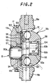
- Fig. 2 is a cross sectional view of a power roller according to an embodiment this invention.
- Fig. 3 is a cross sectional view of a power roller according to another embodiment of this invention.
- Fig. 4 is a cross sectional view of a power roller according to yet another embodiment of this invention.
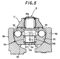
- Fig. 5 is a cross sectional view of a power roller according to yet another embodiment of this invention.
- Fig. 1 is a schematic vew of the overall structure of a toroidal continuously variable transmission.
- a rotational drive force from an engine is input through a torque converter 12 to the toroidal continuously variable transmission 10.
- the torque converter 12 comprises a pump impeller 12a, a turbine runner 12b, a stator 12c, a lock-up clutch 12d, an applying oil chamber 12e and a releasing oil chamber 12f.
- An impeller shaft 14 pierces a central part of the torque converter 12 and the rotations of the turbine runner 12b are transmitted to the impeller shaft 14.
- the impeller shaft 14 is connected to a forward/reverse switching mechanism 36.
- the forward/reverse switching mechanism 36 selectively switches the rotational direction of engine rotations which are transmitted to the continuously variable transmission 10.
- the forward/reverse switching mechanism 36 is provided with a planetary gear mechanism 42, a forward clutch 44 and a reverse clutch 46.
- the planetary gear mechanism 36 comprises a pinion carrier 42a which supports pinions, a ring gear 42b which meshes with respective pinions and is disposed on an outer side of the pinions and a sun gear 42c which is disposed on an inner side of the pinions.
- a rotation shaft 42d which is connected to the pinion carrier 42a of the planetary gear mechanism 42 acts as the output shaft of the forward/reverse switching mechanism 36 and is disposed coaxially to a torque transmission shaft 16 of the continuously variable transmission 10.
- a first continuously variable mechanism 18 and a second continuously variable mechanism 20 are disposed in tandem on the torque transmission shaft 16 inside the transmission case 22.
- the first continuously variable mechanism 18 comprises an input disk 18a and output disk 18b which have opposed toroidal faces and a pair of power rollers 18c, 18d which are sandwiched between the opposed faces of the input and output disks 18a, 18b.
- the power rollers 18c, 18d are supported to enable varying an angle of gyration due to support by a support member termed a trunnion which is described hereafter.
- the rotation speed transmitted to the output disk 18b from the input disk 18a is varied in response to the gyration angle.
- the second continuously variable mechanism 20 has a similar structure to the first continuously variable mechanism 18 and is provided with an input disk 20a, an output disk 20b and a pair of power rollers 20c, 20d sandwiched by the input and output disks 20a, 20b.
- the power rollers 18c, 18d and power rollers 20c, 20d are adapted to vary an angle of gyration synchronously by the displacement of the trunnions.
- the output disks 18b, 20b of both continuously variable mechanisms 18, 20 are supported to rotate freely coaxial to the torque transmission shaft 16.
- the output disks 18b, 20b are disposed to be mutually adjacent and opposed. Moreover the output disks 18b, 20b rotate together by being interconnected.
- the input disks 18a, 20a are separated in opposed directions and are supported on the torque transmission shaft 16 through ball splines 16, 26.
- the input disks 18a, 20a rotate together with the torque transmission shaft 16, they are capable of displacing in an axial direction.
- One input disk 18a is pressed from its rear face in an axial direction towards the right in the drawing by a loading cam device 34 which generates a pressing force which is input through the torque converter 12 in response to an input torque, according to this, power rollers 18c, 20c are gripped strongly between the input disks 18a, 20a and output disks 18b, 20b so that the power rollers do not slip even when the large torque is input between the input disks and the output disks.
- the other input disk 20a is pressed by a plate spring 40 to generate pre-load on the power rollers 18c, 20c to prevent a slip during no load.
- the loading cam device 34 has a loading cam 34a and is supported to rotate freely on a torque transmission shaft 16 through a slide bearing 38.
- the loading cam 34a of the loading cam device 34 which rotates together with the rotation shaft 42d presses the rear face of the input disk 18a and synchronizes the rotation of the input disk 18a. That rotation is transmitted to the opposite input disk 20a through a torque transmission shaft 16. In this manner, the input disks 18a, 20a of the first and second continuously variable mechanisms 18, 20 rotate in synchronization and the rotation is transmitted to the output disks 18b, 20b through the power rollers.
- the output disks 18b, 20b are spline jointed to an output gear 28 which is supported to rotate relative to and coaxial to the torque transmission shaft 16.
- the rotations of the output disks 18b, 20b are transmitted to a gear 30a which is connected to a counter shaft 30 through an output gear 28.
- These gears 28, 30a comprise a first rotation transmission mechanism 32.
- a gear 52 provided on the counter shaft 30 and a gear 56 provided on transmission output shaft 50 meshes via an idle gear 54 and thus comprise a second rotation transmission mechanism 48.
- the output shaft 50 transmits these rotations to the vehicle propeller shaft 60.
- the power roller 18c is taken to be representative of the power rollers 18c, 18d, 20c,20d and is described on the basis of Fig. 2.
- the other power rollers 18d, 20c, 20d have the same structure.
- Shafts 19a, 19b are provided on the top and bottom of a trunnion 17 which functions as a support member for the power roller 18c and a support part 17a is formed eccentrically to the shafts 19a, 19b.
- a power roller storage portion 91 is formed on the support member 17a.
- the power roller 18c is supported to rotate through a pivot shaft 15 in the power roller storage portion 91.
- the pivot shaft 15 is provided on the support part 17a of the trunnion 17 at right angles to the shafts 19a, 19b.
- the power roller 18c comprises an inner roller 93 making frictional contact with the input and output disks 18a, 18b and an outer roller 94 which supports a thrust force applied to the inner roller 94 through a ball bearing 92.
- a support plate 95 is fixed to a flat part of the power roller storage portion 91 on a rear face of the outer roller 94.
- a thrust bearing 96 is interposed between the support plate 95 and the outer roller 94.
- An inner radial hole 93a is formed in a central part of the inner roller 93 in order to allow insertion of a section of the pivot shaft 15.
- the inner radial hole 93a has an opening faced to the outer roller 94, however the bottom part 93b of the hole is covered, the inner radial hole 93a takes the form of a recessed hole. This structure creates high rigidity and mechanical strength in the inner roller 93 since the side supporting a large sandwiching load from the input and output disks 18a, 18b is connected by the bottom part 93b.
- the pivot shaft 15 comprises a trunnion shaft portion 90a and a power roller shaft portion 90b disposed eccentrically to the trunnion shaft portion 90a.
- the pivot shaft 15 is supported by a first roller bearing 97 at the trunnion shaft portion 90a to rotate with respect to the trunnion 17a.
- the inner roller 93 is supported free to rotate to the power roller shaft portion 90b through a second roller bearing 98 and outer roller 94 is also supported to the power roller shaft portion90b.
- a first lubrication oil passage 100 is formed in the trunnion 17 to introduce lubrication oil supplied by an oil pressure unit (not shown).
- Two branching oil passages 101, 102 are formed in order to supply a lubrication oil to the thrust bearing 96 from the first lubrication oil passage 100.
- a second lubrication oil passage 103 is formed on the outer roller 94 to supply further lubrication oil in the thrust bearing 96 to the ball bearing 92.
- a lubrication oil passage 104 is formed in the power roller shaft portion 90b of the pivot shaft 15 to introduce lubrication oil from the thrust bearing 96 through the branching oil passage 101 in an axial direction.
- Radial lubrication oil passages 105, 106 are formed which branch at right angles from the lubrication oil passage 104 and which supply lubrication oil respectively to the ball bearing 92 and the roller bearing 98.
- a large load is applied to the inner roller 93 in response to drive force transmitted between the inner roller 93 and the input and output disks 18a, 18b. This load tends to create an inward deformation in the inner roller 93.
- the inner radial hole 93a provided in an inner part of the inner roller 93 is covered by a bottom part 93b on the side to which the load is applied from the input and output disks 18a, 18b, therefore it is possible to increase component durability and to prevent deformation.
- the power roller 18c normally realizes smooth transmission of rotations while sandwiched between the input disk 18a and the output disk 18c.
- the inner rollers of the other power rollers 18d, 20c, 20d show the same effect.
- the inner radial hole 93a of the inner roller 93 is covered by a bottom part 93b and lubrication oil is effectively supplied to the second roller bearing 98 or the ball bearing 92 through the radial lubrication oil passage 105, 106 and the lubrication oil passage 104 of the pivot shaft 15 from the branching oil passage 101 and the first lubrication oil passage 100 of the trunnion 17.
- This arrangement allows for sufficient lubrication of the bearing of the inner roller 93 and it is possible to maintain smooth rotational motion. This increases durability of the bearings 92, 98 and the power roller 18c.
- the other power rollers 18d, 20c, 20d show the same effect.
- a washer or a snap ring is provided on parts in which the pivot shaft projects from the tip of the inner roller in order to prevent detachment of the inner roller.
- the inner radial hole 93a of the inner roller 93 has a bottom part 93b in this invention, it is possible to omit the snap ring or washer which thus reduces the number of components and also reduces processing steps as a snap ring groove need not be provided.
- the ball bearing 92 is set so that the position of contact with the inner roller 93 and outer roller 94 differs in a radial direction about the rotational center of the power roller 18c.
- a line L of application of the load on the ball bearing 92 is set to incline with respect to the rotational center of the power roller 18c so that the point of contact between the orbit 93c of the inner roller 93 and the ball bearing 92 diverges from the rotational center of the power roller 18c and the point of contact of the orbit 94a of the outer roller 94 and the ball bearing 92 converges towards the central axis of the power roller 18c.
- the inner radial hole 93a provided in an inner part of the inner roller 93 is also covered by a bottom part 93b on the side to which the load is applied from the input and output disks 18a, 18b, therefore it is possible to increase component durability and to prevent deformation.
- This embodiment differs from the second embodiment in that a lubrication oil passage 104 which is provided on the power roller shaft portion 90b is pierced in an axial direction in order to supply lubrication oil to the second roller bearing 98 disposed between the inner roller 93 and the pivot shaft 15.
- the pierced lubrication oil passage is designated by the reference numeral 104'.
- Lubrication oil from the lubrication oil passage 104' of the power roller shaft portion 90b reaches the bottom part 93b of the inner radial hole 93a and it is possible to supply sufficient lubrication oil to the second roller bearing 98.
- lubrication holes 107 which supply lubrication oil to the moving faces of the input and output disks 18a, 18b are provided at two positions on the bottom part 93b of the inner roller 93.
- the lubrication oil which is introduced to the inner radial hole 93a through the lubrication oil passage 104 of the inner part of the pivot shaft 15 is discharged outwardly from the lubrication oil holes 107 and is supplied to the moving faces of the input and output disks 18a, 18b.
- the lubrication oil passage 104 formed in the power roller shaft 90b may be provided as a pierced lubrication oil passage 104'.
Landscapes
- Engineering & Computer Science (AREA)
- General Engineering & Computer Science (AREA)
- Mechanical Engineering (AREA)
- Friction Gearing (AREA)
- Rolling Contact Bearings (AREA)
- General Details Of Gearings (AREA)
Abstract
Description
- This invention relates to a toroidal continuously variable transmission for a vehicle, in particular relates to improvements in a power roller sandwiched between an input disk and an output disk.
- The power roller of a toroidal continuously variable transmission is sandwiched between an input disk and an output disk so as to transmit the rotations of the input disk to the output disk. The structure of such a power roller is disclosed in JP-A-7-229549 published by the Japanese Patent Office in 1995.
- The power roller comprises an inner roller which makes contact with the input and output disks and an outer roller which supports a load applied on the inner roller through a ball bearing. A through hole is provided on the central axis of the inner roller to allow insertion of pivot shaft of a trunnion. Therefore the problem has arisen that when a large load is applied by the input and output disks, the inner roller displays a tendency to undergo compression deformation inwardly.
- This deformation results in a deterioration in component durability and hinders the smooth transmission of a rotation torque by the power roller.
- The present invention is proposed to solve the above problem and has the object of avoiding deformation of the inner roller of the power roller and maintaining smooth rotational motion.
- A further object of this invention is to increase the durability of the power roller.
- In order to achieve above the objects, the invention provides a toroidal continuously variable transmission which comprises an input disk and output disk disposed co-axially in an opposed orientation, a power roller which is sandwiched in order to transmit drive force between the input and output disks, and a trunnion which supports the power roller to rotate freely on a pivot shaft. The power roller comprises an inner roller making frictional contact between the input and output disks and an outer roller supporting a contact load input from the input and output disks to the inner roller through a ball bearing, and an inner radial hole to support a pivot shaft is formed on a rotational center of the inner roller, the inner radial hole opens toward the outer roller and is covered by a bottom part on a side faced to the input and output disks.
- The details as well as other features and advantages of the invention are set forth in the remainder of the specification and are shown in the accompanying drawings.
- Fig. 1 is a schematic view of the overall structure of the toroidal continuously variable transmission of this invention.
- Fig. 2 is a cross sectional view of a power roller according to an embodiment this invention.
- Fig. 3 is a cross sectional view of a power roller according to another embodiment of this invention.
- Fig. 4 is a cross sectional view of a power roller according to yet another embodiment of this invention.
- Fig. 5 is a cross sectional view of a power roller according to yet another embodiment of this invention.
- Fig. 1 is a schematic vew of the overall structure of a toroidal continuously variable transmission.
- A rotational drive force from an engine (not shown) is input through a
torque converter 12 to the toroidal continuouslyvariable transmission 10. Thetorque converter 12 comprises apump impeller 12a, aturbine runner 12b, astator 12c, a lock-up clutch 12d, an applyingoil chamber 12e and a releasingoil chamber 12f. - An
impeller shaft 14 pierces a central part of thetorque converter 12 and the rotations of theturbine runner 12b are transmitted to theimpeller shaft 14. - The
impeller shaft 14 is connected to a forward/reverse switching mechanism 36. The forward/reverse switching mechanism 36 selectively switches the rotational direction of engine rotations which are transmitted to the continuouslyvariable transmission 10. - For this purpose, the forward/
reverse switching mechanism 36 is provided with aplanetary gear mechanism 42, aforward clutch 44 and a reverse clutch 46. Theplanetary gear mechanism 36 comprises apinion carrier 42a which supports pinions, aring gear 42b which meshes with respective pinions and is disposed on an outer side of the pinions and a sun gear 42c which is disposed on an inner side of the pinions. - A
rotation shaft 42d which is connected to thepinion carrier 42a of theplanetary gear mechanism 42 acts as the output shaft of the forward/reverse switching mechanism 36 and is disposed coaxially to a torque transmission shaft 16 of the continuouslyvariable transmission 10. A first continuouslyvariable mechanism 18 and a second continuouslyvariable mechanism 20 are disposed in tandem on the torque transmission shaft 16 inside thetransmission case 22. - The first continuously
variable mechanism 18 comprises aninput disk 18a andoutput disk 18b which have opposed toroidal faces and a pair ofpower rollers 18c, 18d which are sandwiched between the opposed faces of the input andoutput disks - The
power rollers 18c, 18d are supported to enable varying an angle of gyration due to support by a support member termed a trunnion which is described hereafter. The rotation speed transmitted to theoutput disk 18b from theinput disk 18a is varied in response to the gyration angle. - The second continuously
variable mechanism 20 has a similar structure to the first continuouslyvariable mechanism 18 and is provided with aninput disk 20a, anoutput disk 20b and a pair ofpower rollers 20c, 20d sandwiched by the input andoutput disks - The
power rollers 18c, 18d andpower rollers 20c, 20d are adapted to vary an angle of gyration synchronously by the displacement of the trunnions. - The
output disks variable mechanisms output disks output disks - In contrast, the
input disks input disks - One
input disk 18a is pressed from its rear face in an axial direction towards the right in the drawing by aloading cam device 34 which generates a pressing force which is input through thetorque converter 12 in response to an input torque, according to this,power rollers input disks output disks - The
other input disk 20a is pressed by aplate spring 40 to generate pre-load on thepower rollers - The
loading cam device 34 has a loading cam 34a and is supported to rotate freely on a torque transmission shaft 16 through a slide bearing 38. - The loading cam 34a of the
loading cam device 34 which rotates together with therotation shaft 42d presses the rear face of theinput disk 18a and synchronizes the rotation of theinput disk 18a. That rotation is transmitted to theopposite input disk 20a through a torque transmission shaft 16. In this manner, theinput disks variable mechanisms output disks - The
output disks output gear 28 which is supported to rotate relative to and coaxial to the torque transmission shaft 16. The rotations of theoutput disks output gear 28. Thesegears 28, 30a comprise a first rotation transmission mechanism 32. Furthermore agear 52 provided on the counter shaft 30 and agear 56 provided ontransmission output shaft 50 meshes via anidle gear 54 and thus comprise a secondrotation transmission mechanism 48. Theoutput shaft 50 transmits these rotations to thevehicle propeller shaft 60. - The
power roller 18c is taken to be representative of thepower rollers other power rollers 18d, 20c, 20d have the same structure. - Shafts 19a, 19b are provided on the top and bottom of a
trunnion 17 which functions as a support member for thepower roller 18c and asupport part 17a is formed eccentrically to theshafts roller storage portion 91 is formed on thesupport member 17a. Thepower roller 18c is supported to rotate through apivot shaft 15 in the powerroller storage portion 91. Thepivot shaft 15 is provided on thesupport part 17a of thetrunnion 17 at right angles to theshafts - When the
trunnion 17 is displaced vertically by a hydraulic cylinder (not shown), a gyration force is generated at the contact point between thepower roller 18c and input andoutput disks 18c, 18d according to the deviation of the center axis of the input and output disks18c, 18d and thepivot shaft 15, so that the angle of gyration of thepower roller 18c is varied by a fluctuating motion of thetrunnion 17 about theshaft input disk 18a to theoutput disk 18b is varied. - The
power roller 18c comprises aninner roller 93 making frictional contact with the input andoutput disks outer roller 94 which supports a thrust force applied to theinner roller 94 through a ball bearing 92. Asupport plate 95 is fixed to a flat part of the powerroller storage portion 91 on a rear face of theouter roller 94. A thrust bearing 96 is interposed between thesupport plate 95 and theouter roller 94. - An inclined sandwiching load is applied in a direction shown by the arrow in Fig. 5 as for reference to the
inner roller 93 which is gripped by the input andoutput disks outer roller 94 through a ball bearing 92. At the same time, the thrust force is transmitted from theouter roller 96 to thesupport part 17a through athrust bearing 96, lastly this thrust load is supported by thetrunnion 17. - An inner
radial hole 93a is formed in a central part of theinner roller 93 in order to allow insertion of a section of thepivot shaft 15. The innerradial hole 93a has an opening faced to theouter roller 94, however thebottom part 93b of the hole is covered, the innerradial hole 93a takes the form of a recessed hole. This structure creates high rigidity and mechanical strength in theinner roller 93 since the side supporting a large sandwiching load from the input andoutput disks bottom part 93b. - Since the inner
radial hole 93a allows insertion a part of thepivot shaft 15, the provision of a recessed hole prevents inward deformation of the inner roller even with respect to loads which would not be supported by a through hole as employed in the prior art. - The
pivot shaft 15 comprises atrunnion shaft portion 90a and a powerroller shaft portion 90b disposed eccentrically to thetrunnion shaft portion 90a. Thepivot shaft 15 is supported by afirst roller bearing 97 at thetrunnion shaft portion 90a to rotate with respect to thetrunnion 17a. Theinner roller 93 is supported free to rotate to the powerroller shaft portion 90b through asecond roller bearing 98 andouter roller 94 is also supported to the power roller shaft portion90b. - Lubrication of the bearing will be described below.
- A first
lubrication oil passage 100 is formed in thetrunnion 17 to introduce lubrication oil supplied by an oil pressure unit (not shown). Two branchingoil passages lubrication oil passage 100. A secondlubrication oil passage 103 is formed on theouter roller 94 to supply further lubrication oil in the thrust bearing 96 to theball bearing 92. - A
lubrication oil passage 104 is formed in the powerroller shaft portion 90b of thepivot shaft 15 to introduce lubrication oil from the thrust bearing 96 through the branchingoil passage 101 in an axial direction. Radiallubrication oil passages lubrication oil passage 104 and which supply lubrication oil respectively to theball bearing 92 and theroller bearing 98. - The effect of the invention will be described below.
- A large load is applied to the
inner roller 93 in response to drive force transmitted between theinner roller 93 and the input andoutput disks inner roller 93. However the innerradial hole 93a provided in an inner part of theinner roller 93 is covered by abottom part 93b on the side to which the load is applied from the input andoutput disks - As a result, since the
inner roller 93 does not deform, thepower roller 18c normally realizes smooth transmission of rotations while sandwiched between theinput disk 18a and theoutput disk 18c. - The inner rollers of the
other power rollers 18d, 20c, 20d show the same effect. - The inner
radial hole 93a of theinner roller 93 is covered by abottom part 93b and lubrication oil is effectively supplied to thesecond roller bearing 98 or theball bearing 92 through the radiallubrication oil passage lubrication oil passage 104 of thepivot shaft 15 from the branchingoil passage 101 and the firstlubrication oil passage 100 of thetrunnion 17. This arrangement allows for sufficient lubrication of the bearing of theinner roller 93 and it is possible to maintain smooth rotational motion. This increases durability of thebearings power roller 18c. - The
other power rollers 18d, 20c, 20d show the same effect. - During manufacture of prior art devices, a washer or a snap ring is provided on parts in which the pivot shaft projects from the tip of the inner roller in order to prevent detachment of the inner roller. However since the inner
radial hole 93a of theinner roller 93 has abottom part 93b in this invention, it is possible to omit the snap ring or washer which thus reduces the number of components and also reduces processing steps as a snap ring groove need not be provided. - Another embodiment of this invention will be described below.
- In the embodiment as shown in Fig. 3, the
ball bearing 92 is set so that the position of contact with theinner roller 93 andouter roller 94 differs in a radial direction about the rotational center of thepower roller 18c. - A line L of application of the load on the
ball bearing 92 is set to incline with respect to the rotational center of thepower roller 18c so that the point of contact between theorbit 93c of theinner roller 93 and theball bearing 92 diverges from the rotational center of thepower roller 18c and the point of contact of theorbit 94a of theouter roller 94 and theball bearing 92 converges towards the central axis of thepower roller 18c. - As a result, since a radial load applied on the
inner roller 93 is supported by theball bearing 92 provided at an inclined contact angle, theinner roller 93 does not tend to displace in a radial direction which thus increases the supporting rigidity of that component. - The inner
radial hole 93a provided in an inner part of theinner roller 93 is also covered by abottom part 93b on the side to which the load is applied from the input andoutput disks - A further embodiment of this invention will be described below with reference to Fig. 4.
- This embodiment differs from the second embodiment in that a
lubrication oil passage 104 which is provided on the powerroller shaft portion 90b is pierced in an axial direction in order to supply lubrication oil to thesecond roller bearing 98 disposed between theinner roller 93 and thepivot shaft 15. - That is to say, the pierced lubrication oil passage is designated by the reference numeral 104'. Lubrication oil from the lubrication oil passage 104' of the power
roller shaft portion 90b reaches thebottom part 93b of the innerradial hole 93a and it is possible to supply sufficient lubrication oil to thesecond roller bearing 98. - Yet another embodiment of the invention will be described below.
- As shown in Fig. 5, lubrication holes 107 which supply lubrication oil to the moving faces of the input and
output disks bottom part 93b of theinner roller 93. - The lubrication oil which is introduced to the inner
radial hole 93a through thelubrication oil passage 104 of the inner part of thepivot shaft 15 is discharged outwardly from the lubrication oil holes 107 and is supplied to the moving faces of the input andoutput disks - In this manner, lubrication of the moving faces of the input and
output disks power roller 18c is effectively performed and thus it is possible to improve the durability of the moving faces of the input and output disks with respect to fatigue. - In this case, the
lubrication oil passage 104 formed in thepower roller shaft 90b may be provided as a pierced lubrication oil passage 104'. - The entire content of Japanese Patent Application P2000-100668 (filed April 3, 2000) is incorporated herein by reference.
- This invention is not limited to the above embodiments and various changes and modifications may be made in the invention without departing from the spirit and scope thereof.
Claims (4)
- A toroidal continuously variable transmission comprising:an input disk (18a, 20a) and an output disk (18b, 20b) disposed co-axially in an opposed orientation,a power roller (18c, 18d, 20c, 20d) which is sandwiched in order to transmit drive force between the input and output disks (18a,20a)(18b,20b), anda trunnion (17) which supports the power roller (18c, 18d, 20c, 20d) rotatively on a pivot shaft (15),wherein:
the power roller (18c, 18d, 20c, 20d) comprises an inner roller (93) making frictional contact between the input and output disks (18a, 20a), (18b, 20b) and an outer roller (94) supporting a contact load input from the input and output disks (18a, 20a), (18b, 20b) to the inner roller (93) through a ball bearing (92), and an inner radial hole (93a) to support the pivot shaft (15) is formed on a rotational center of the inner roller (93), the inner radial hole (93a) opens toward the outer roller (94) and is covered by a bottom part (93b) on a side faced to the input and output disks (18a,20a)(18b,20b). - The toroidal continuously variable transmission as defined by Claim 1, wherein a point of contact between an orbit (93c) of the inner roller (93) and the ball bearing (92) diverges from the rotational center of the power roller and a point of contact between an orbit (94a) of the outer roller (94) and the ball bearing (92) converges towards the central axis of the power roller, the line of application of a load with respect to a ball bearing (92) is inclined with respect to a rotational center of the power roller.
- The toroidal continuously variable transmission as defined in Claim 1, wherein a roller bearing (98) is provided between an inner radial hole (93a) of the inner roller (93) and the pivot shaft (15), and lubrication oil is supplied to the roller bearing (98) from a lubrication oil passage (104) pierced in the axial direction on an inner part of the pivot shaft (15).
- The toroidal continuously variable transmission as defined in Claim 3, wherein a lubrication hole (107) piercing the bottom part (93b) of the inner radial hole (93a) is provided , and lubrication oil is supplied to respect to moving faces of the input and output disks (18a, 20a), (18b, 20b) from the lubrication hole (107).
Applications Claiming Priority (2)
| Application Number | Priority Date | Filing Date | Title |
|---|---|---|---|
| JP2000100668 | 2000-04-03 | ||
| JP2000100668A JP3506230B2 (en) | 2000-04-03 | 2000-04-03 | Toroidal type continuously variable transmission |
Publications (3)
| Publication Number | Publication Date |
|---|---|
| EP1143167A2 true EP1143167A2 (en) | 2001-10-10 |
| EP1143167A3 EP1143167A3 (en) | 2002-04-03 |
| EP1143167B1 EP1143167B1 (en) | 2003-10-08 |
Family
ID=18614835
Family Applications (1)
| Application Number | Title | Priority Date | Filing Date |
|---|---|---|---|
| EP01108420A Expired - Lifetime EP1143167B1 (en) | 2000-04-03 | 2001-04-03 | Toroidal continuously variable transmission |
Country Status (4)
| Country | Link |
|---|---|
| US (1) | US6524213B2 (en) |
| EP (1) | EP1143167B1 (en) |
| JP (1) | JP3506230B2 (en) |
| DE (1) | DE60100916T2 (en) |
Cited By (3)
| Publication number | Priority date | Publication date | Assignee | Title |
|---|---|---|---|---|
| WO2005080825A1 (en) | 2004-02-24 | 2005-09-01 | Daimlerchrysler Ag | Infinitely variable variator for a toroidal drive of a motor vehicle |
| US10145387B2 (en) | 2015-05-19 | 2018-12-04 | Rolls-Royce Plc | Compressor tip injector |
| US10371059B2 (en) | 2014-12-11 | 2019-08-06 | Rolls-Royce Plc | Cabin blower system |
Families Citing this family (8)
| Publication number | Priority date | Publication date | Assignee | Title |
|---|---|---|---|---|
| JP2003176862A (en) * | 2001-12-11 | 2003-06-27 | Jatco Ltd | Power transmission device |
| CN1333185C (en) * | 2003-07-28 | 2007-08-22 | 崔光彩 | Roller spherical face arc dish stepless speed variator |
| JP4968522B2 (en) * | 2007-05-13 | 2012-07-04 | 日本精工株式会社 | Toroidal continuously variable transmission |
| WO2014117167A1 (en) | 2013-01-28 | 2014-07-31 | Robert Hornblower Meyer | Continuously variable drive mechanism |
| JP2018537632A (en) * | 2015-12-10 | 2018-12-20 | トランスミッション・シーヴイティーコープ・インコーポレーテッド | Roller cooling device for toroidal CVT |
| JP7089354B2 (en) * | 2017-10-27 | 2022-06-22 | 川崎重工業株式会社 | Toroidal continuously variable transmission |
| JP7560284B2 (en) | 2020-07-20 | 2024-10-02 | 日本精工株式会社 | Toroidal type continuously variable transmission |
| JP2023032562A (en) * | 2021-08-27 | 2023-03-09 | 日本精工株式会社 | toroidal type continuously variable transmission |
Citations (2)
| Publication number | Priority date | Publication date | Assignee | Title |
|---|---|---|---|---|
| JPH07229549A (en) | 1994-02-18 | 1995-08-29 | Nippon Seiko Kk | Thrust ball bearings for power rollers |
| JP2000100668A (en) | 1998-09-22 | 2000-04-07 | Okamura Kenkyusho:Kk | Manufacturing method of electric double layer capacitor |
Family Cites Families (17)
| Publication number | Priority date | Publication date | Assignee | Title |
|---|---|---|---|---|
| US4126052A (en) | 1975-12-11 | 1978-11-21 | Jackman Charles W | Friction transmission |
| US4464946A (en) | 1983-01-26 | 1984-08-14 | Excelermatic Inc. | Control arrangement for the supply of lubricant to the bearings of an infinitely variable traction roller transmission |
| US4718294A (en) | 1985-02-28 | 1988-01-12 | Nippon Seiko Kabushiki Kaisha | Ratio control spool valve for a toroidal type infinitely variable traction roller transmission |
| US4694704A (en) | 1986-08-04 | 1987-09-22 | Excelermatic Inc. | Infinitely variable traction roller transmission |
| US5536091A (en) * | 1994-02-18 | 1996-07-16 | Nsk Ltd. | Thrust ball bearing for use with power rollers |
| US5720689A (en) * | 1995-03-03 | 1998-02-24 | Nsk Ltd. | Trunnion arrangement for a toroidal type continuously variable transmission |
| JP3508391B2 (en) * | 1996-05-29 | 2004-03-22 | 日本精工株式会社 | Toroidal type continuously variable transmission |
| JP3237573B2 (en) * | 1997-06-05 | 2001-12-10 | 日産自動車株式会社 | Friction wheel type continuously variable transmission |
| US6174257B1 (en) * | 1997-07-04 | 2001-01-16 | Nsk Ltd. | Toroidal type continuously variable transmission |
| US6238318B1 (en) * | 1997-11-21 | 2001-05-29 | Nsk Ltd. | Power roller unit and output disc unit for torodial type continuously variable transmission |
| JP3791172B2 (en) * | 1998-02-10 | 2006-06-28 | 日本精工株式会社 | Synchronous cable for toroidal continuously variable transmission |
| JP3496513B2 (en) * | 1998-05-13 | 2004-02-16 | 日産自動車株式会社 | Toroidal type continuously variable transmission |
| JP3521747B2 (en) * | 1998-07-08 | 2004-04-19 | 日産自動車株式会社 | Friction wheel type continuously variable transmission |
| JP2000046135A (en) * | 1998-07-28 | 2000-02-18 | Nissan Motor Co Ltd | Transmission control device for toroidal type continuously variable transmission |
| JP3592093B2 (en) * | 1998-08-10 | 2004-11-24 | ジヤトコ株式会社 | Lubrication structure of toroidal type continuously variable automatic transmission |
| US6261203B1 (en) * | 1998-12-28 | 2001-07-17 | Nsk Ltd. | Toroidal type continuously variable transmission |
| JP3870592B2 (en) * | 1999-01-11 | 2007-01-17 | 日本精工株式会社 | Half toroidal continuously variable transmission |
-
2000
- 2000-04-03 JP JP2000100668A patent/JP3506230B2/en not_active Expired - Fee Related
-
2001
- 2001-03-30 US US09/821,088 patent/US6524213B2/en not_active Expired - Fee Related
- 2001-04-03 DE DE60100916T patent/DE60100916T2/en not_active Expired - Fee Related
- 2001-04-03 EP EP01108420A patent/EP1143167B1/en not_active Expired - Lifetime
Patent Citations (2)
| Publication number | Priority date | Publication date | Assignee | Title |
|---|---|---|---|---|
| JPH07229549A (en) | 1994-02-18 | 1995-08-29 | Nippon Seiko Kk | Thrust ball bearings for power rollers |
| JP2000100668A (en) | 1998-09-22 | 2000-04-07 | Okamura Kenkyusho:Kk | Manufacturing method of electric double layer capacitor |
Cited By (4)
| Publication number | Priority date | Publication date | Assignee | Title |
|---|---|---|---|---|
| WO2005080825A1 (en) | 2004-02-24 | 2005-09-01 | Daimlerchrysler Ag | Infinitely variable variator for a toroidal drive of a motor vehicle |
| US7476175B2 (en) | 2004-02-24 | 2009-01-13 | Daimler Ag | Variator for an infinitely variable toroidal drive of a motor vehicle |
| US10371059B2 (en) | 2014-12-11 | 2019-08-06 | Rolls-Royce Plc | Cabin blower system |
| US10145387B2 (en) | 2015-05-19 | 2018-12-04 | Rolls-Royce Plc | Compressor tip injector |
Also Published As
| Publication number | Publication date |
|---|---|
| DE60100916D1 (en) | 2003-11-13 |
| JP2001289297A (en) | 2001-10-19 |
| JP3506230B2 (en) | 2004-03-15 |
| EP1143167A3 (en) | 2002-04-03 |
| US6524213B2 (en) | 2003-02-25 |
| EP1143167B1 (en) | 2003-10-08 |
| DE60100916T2 (en) | 2004-05-13 |
| US20010027145A1 (en) | 2001-10-04 |
Similar Documents
| Publication | Publication Date | Title |
|---|---|---|
| JP4254051B2 (en) | Toroidal continuously variable transmission | |
| US6524213B2 (en) | Toroidal continuously variable transmission | |
| JPH02261950A (en) | Loading cam device of toroidal continuous variable transmission | |
| US6517461B2 (en) | Infinitely variable transmission | |
| JP2002106667A (en) | Toroidal type continuously variable transmission | |
| US7326146B2 (en) | Toroidal-type continuously variable transmission and continuously variable transmission apparatus | |
| EP1106868A1 (en) | Toroidal continuously variable transmission | |
| US6616564B2 (en) | Infinitely variable transmission | |
| JP2000291759A (en) | Continuously variable transmission | |
| JP3752587B2 (en) | Toroidal continuously variable transmission | |
| JP3211970B2 (en) | Toroidal continuously variable transmission | |
| JPH09310745A (en) | Friction car type continuously variable transmission | |
| JPH11280867A (en) | Continuously variable transmission | |
| JPH07122452B2 (en) | V-belt type continuously variable transmission | |
| JP3506225B2 (en) | Toroidal type continuously variable transmission | |
| JP3674264B2 (en) | Continuously variable transmission | |
| US20020058563A1 (en) | Frictional variable transmission for vehicle | |
| US6514171B2 (en) | Toroidal continuously variable transmission | |
| JPH0721947Y2 (en) | Belt type continuously variable transmission | |
| JP2003090403A (en) | Toroidal type continuously variable transmission | |
| JPH0536124U (en) | Thrust bearing structure of planetary gear in automatic transmission | |
| JP2002031205A (en) | Toroidal type continuously variable transmission | |
| JPH02129441A (en) | Shaft support structure in automatic transmission | |
| JP2002349660A (en) | Toroidal type continuously variable transmission | |
| JP2003090406A (en) | Toroidal type continuously variable transmission |
Legal Events
| Date | Code | Title | Description |
|---|---|---|---|
| PUAI | Public reference made under article 153(3) epc to a published international application that has entered the european phase |
Free format text: ORIGINAL CODE: 0009012 |
|
| 17P | Request for examination filed |
Effective date: 20010403 |
|
| AK | Designated contracting states |
Kind code of ref document: A2 Designated state(s): AT BE CH CY DE DK ES FI FR GB GR IE IT LI LU MC NL PT SE TR Kind code of ref document: A2 Designated state(s): DE FR GB |
|
| AX | Request for extension of the european patent |
Free format text: AL;LT;LV;MK;RO;SI |
|
| PUAL | Search report despatched |
Free format text: ORIGINAL CODE: 0009013 |
|
| AK | Designated contracting states |
Kind code of ref document: A3 Designated state(s): AT BE CH CY DE DK ES FI FR GB GR IE IT LI LU MC NL PT SE TR |
|
| AX | Request for extension of the european patent |
Free format text: AL;LT;LV;MK;RO;SI |
|
| 17Q | First examination report despatched |
Effective date: 20020712 |
|
| AKX | Designation fees paid |
Free format text: DE FR GB |
|
| GRAH | Despatch of communication of intention to grant a patent |
Free format text: ORIGINAL CODE: EPIDOS IGRA |
|
| GRAS | Grant fee paid |
Free format text: ORIGINAL CODE: EPIDOSNIGR3 |
|
| GRAA | (expected) grant |
Free format text: ORIGINAL CODE: 0009210 |
|
| AK | Designated contracting states |
Kind code of ref document: B1 Designated state(s): DE FR GB |
|
| REG | Reference to a national code |
Ref country code: GB Ref legal event code: FG4D |
|
| REG | Reference to a national code |
Ref country code: IE Ref legal event code: FG4D |
|
| REF | Corresponds to: |
Ref document number: 60100916 Country of ref document: DE Date of ref document: 20031113 Kind code of ref document: P |
|
| ET | Fr: translation filed | ||
| PLBE | No opposition filed within time limit |
Free format text: ORIGINAL CODE: 0009261 |
|
| STAA | Information on the status of an ep patent application or granted ep patent |
Free format text: STATUS: NO OPPOSITION FILED WITHIN TIME LIMIT |
|
| 26N | No opposition filed |
Effective date: 20040709 |
|
| REG | Reference to a national code |
Ref country code: IE Ref legal event code: MM4A |
|
| PGFP | Annual fee paid to national office [announced via postgrant information from national office to epo] |
Ref country code: DE Payment date: 20090327 Year of fee payment: 9 Ref country code: FR Payment date: 20090417 Year of fee payment: 9 |
|
| PGFP | Annual fee paid to national office [announced via postgrant information from national office to epo] |
Ref country code: GB Payment date: 20090401 Year of fee payment: 9 |
|
| GBPC | Gb: european patent ceased through non-payment of renewal fee |
Effective date: 20100403 |
|
| REG | Reference to a national code |
Ref country code: FR Ref legal event code: ST Effective date: 20101230 |
|
| PG25 | Lapsed in a contracting state [announced via postgrant information from national office to epo] |
Ref country code: DE Free format text: LAPSE BECAUSE OF NON-PAYMENT OF DUE FEES Effective date: 20101103 |
|
| PG25 | Lapsed in a contracting state [announced via postgrant information from national office to epo] |
Ref country code: GB Free format text: LAPSE BECAUSE OF NON-PAYMENT OF DUE FEES Effective date: 20100403 |
|
| PG25 | Lapsed in a contracting state [announced via postgrant information from national office to epo] |
Ref country code: FR Free format text: LAPSE BECAUSE OF NON-PAYMENT OF DUE FEES Effective date: 20100430 |