EP1142603A1 - Indwelling needle assembly - Google Patents
Indwelling needle assembly Download PDFInfo
- Publication number
- EP1142603A1 EP1142603A1 EP01107449A EP01107449A EP1142603A1 EP 1142603 A1 EP1142603 A1 EP 1142603A1 EP 01107449 A EP01107449 A EP 01107449A EP 01107449 A EP01107449 A EP 01107449A EP 1142603 A1 EP1142603 A1 EP 1142603A1
- Authority
- EP
- European Patent Office
- Prior art keywords
- needle
- tube
- distal end
- hub
- guard
- Prior art date
- Legal status (The legal status is an assumption and is not a legal conclusion. Google has not performed a legal analysis and makes no representation as to the accuracy of the status listed.)
- Granted
Links
Images


Classifications
-
- A—HUMAN NECESSITIES
- A61—MEDICAL OR VETERINARY SCIENCE; HYGIENE
- A61M—DEVICES FOR INTRODUCING MEDIA INTO, OR ONTO, THE BODY; DEVICES FOR TRANSDUCING BODY MEDIA OR FOR TAKING MEDIA FROM THE BODY; DEVICES FOR PRODUCING OR ENDING SLEEP OR STUPOR
- A61M5/00—Devices for bringing media into the body in a subcutaneous, intra-vascular or intramuscular way; Accessories therefor, e.g. filling or cleaning devices, arm-rests
- A61M5/14—Infusion devices, e.g. infusing by gravity; Blood infusion; Accessories therefor
- A61M5/158—Needles for infusions; Accessories therefor, e.g. for inserting infusion needles, or for holding them on the body
Definitions
- the present invention relates to an indwelling needle assembly including an indwelling needle to be detained temporarily in a blood vessel for an infusion or the like. More specifically, the present invention relates to an indwelling needle assembly in which after an inner needle and an outer needle are pierced simultaneously in a tissue of a living body and the inner needle is removed from the outer needle while detaining the outer needle, the inner needle can be stored within a needle guard safely and easily.
- An indwelling needle used for an infusion or the like generally has a double-needle structure comprising an outer needle and an inner needle inserted in a lumen of the outer needle, and when used, the assembly is pierced into a blood vessel with the inner needle.
- the inner needle is removed from the lumen of the outer needle, and then an infusion line or the like is connected to a proximal end portion of the outer needle to allow an infusion, a liquid medicament or the like to flow into the blood vessel. Therefore, a soft resin product that has less possibility of giving a damage to an inner wall of the blood vessel is used for the outer needle, and a metal product that can be easily pierced into the blood vessel is used for the inner needle.
- an inner needle used for a patient suffering from a blood-borne disease such as acquired immune deficiency syndrome (AIDS) or hepatitis can be an infection vehicle that transmits these diseases not only through the tip but also through the needle itself.
- AIDS acquired immune deficiency syndrome
- Each of these indwelling needle assemblies comprises a tubular housing having an inner needle hub connected to the inner needle therein, and a needle guard slidably disposed between the housing and the inner needle hub and having a catheter connected to a distal end portion thereof, wherein after an outer needle of the indwelling needle assembly pierced into a patient is retained in the patient and the inner needle is removed, the inner needle is stored in the needle guard by sliding the needle guard toward the distal end of the housing.
- an indwelling needle assembly comprising a spring disposed between an inner needle hub and a proximal end portion of a needle guard
- Japanese Patent Laid-Open No.8-215315 Japanese Patent Laid-Open No. 9-103492.
- releasing a push-button locking mechanism allows the spring to urge the inner needle hub toward the proximal end of the needle guard.
- the needle assembly comprising such a push-button locking mechanism, it cannot be restored and thus the needle assembly may be put out of use in a case where a user releases the lock inadvertently by pushing the push-button.
- an object of the present invention to provide an indwelling needle assembly having such a structure that medical personnel can take the inner needle easily into the needle guard using one hand even when a long indwelling needle is used or even when it is used by a person who has small hands, and that cannot be put out of use by erroneous operation.
- the present inventors found that the sliding distance of the needle guard required to store the inner needle can be reduced to about half that of the conventional indwelling needle assemblies by making the needle guard a double-tube structure including an inner tube and an outer tube, and providing a connector for connecting the inner tube and the inner needle hub in the needle guard via the proximal side of the outer tube, and thus the present invention is realized.
- the present invention provides an indwelling needle assembly comprising an outer needle hub having an outer needle to be pierced into a tissue of a living body and retained therein fixed to the distal end portion of the hub, an inner needle hub having an inner needle being insertable into the lumen of the outer needle and having a sharp blade edge at the distal end fixed to the distal end portion of the hub, and a needle guard for accommodating the inner needle and the inner needle hub, characterized in that the needle guard has a double-tube structure including an inner tube and an outer tube, that the needle guard is provided with a connector for connecting the inner needle hub and the inner tube via the proximal side of the needle guard, in that the whole length of the needle guard can be extended by sliding the outer tube toward the proximal end of the inner tube, and in that as the whole length of the needle guard is extended, the inner needle hub is slid within the needle guard toward the proximal end of the needle guard by the connector.
- an indwelling needle assembly of the present invention will hereinafter be further described.
- the present invention is not limited thereto.
- Fig. 1 is a cross sectional view of the indwelling needle assembly according to an embodiment of the present invention showing a state before the inner needle is protected as seen from the side.
- Fig. 2 is a cross sectional view of the indwelling needle assembly shown in Fig. 1 as seen from the top.
- Fig. 3 is a side view of the indwelling needle assembly shown in Fig. 1.
- Fig. 4 is a cross sectional view of the indwelling needle assembly according to an embodiment of the present invention showing a state after the inner needle is protected as seen from the side.
- Fig. 5 is a cross sectional view of the indwelling needle assembly shown in Fig. 4 as seen from the top.
- Fig. 6 is an enlarged cross sectional view of the inner needle hub of the indwelling needle assembly shown in Fig. 1 as seen from the top.
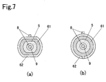
- Figs. 7(a) and (b) are alternative cross sectional views of the indwelling needle assembly shown in Fig. 1 taken along the line A-A.
- Fig. 8 is a cross sectional view of the indwelling needle assembly shown in Fig. 1 taken along the line B-B.
- Fig. 9 is a side view of the connector of the indwelling needle assembly shown in Fig. 1.
- Fig. 10 is a cross sectional view of the indwelling needle assembly according to another embodiment of the present invention showing a state before the inner needle is protected as seen from the side.
- Fig. 11 is a cross sectional view of the indwelling needle assembly according to another embodiment of the present invention in a state after the inner needle is protected as seen from the side.
- Fig. 12 is a cross sectional view of the indwelling needle assembly of the present invention showing embodiments of the proximal end portion of the needle guard.
- the indwelling needle assembly 1 of the present invention comprises an outer needle hub 3 having an outer needle 2 fixed to the distal end portion thereof, an inner needle hub 5 having an inner needle 4 which is insertable into the lumen of the outer needle 2 and having a sharp blade edge 41 at the distal end portion of the inner needle 4 and fixed to the distal end portion of the inner needle hub 5, and a needle guard 6 for accommodating the inner needle 4 and inner needle hub 5 therein.
- the distal end designates the end which is to be pierced into the patient (left side in the figures)
- the proximal end designates the end opposite the distal end (right side in the figures).
- the outer needle 2 is a hollow tube, and the distal end portion is preferably formed in a tapered shape in which the outer diameter is gradually reduced toward the distal end so as to reduce the piercing resistance.
- the outer needle 2, which is inserted into a patient's body and detained for some time therein, is preferably formed of a soft resin that has less possibility of injuring the patient, and more specifically, is an ethylene-tetrafluoroethylene copolymer, a polyurethane, a polyether nylon resin, or the like.
- the outer needle 2 may be broken for example when a patient moves while the outer needle 2 is retained in the patient's body. In order to detect a fragment of the outer needle 2 in such a case, it is also possible to add an X-ray contrast medium such as barium sulfate or the like to the material for the outer needle 2 to provide a contrast medium function to the outer needle 2.
- an X-ray contrast medium such as barium sulfate or the like
- An outer needle hub 3 is fixed to the proximal end portion of the outer needle 2.
- a method of fixing caulking with a caulking pin 31, adhesion by means of an adhesive or fusion bonding by heat can be employed.
- the outer needle hub 3 has a hollow tubular body and is formed in a tapered shape in which the inner diameter increases toward the proximal end. This shape ensures connection of a tube of an infusion set or the like.
- a projection 32 for connecting a luer tapered part of a locking type syringe or tube for an infusion set.
- a hard resin such as polyethylene, polypropylene, a polyolefin such as ethylene-vinyl acetate copolymer, polyvinyl chloride, polybutadiene, polyamide, polyester or the like is employed.
- the inner needle 4 is a hollow tube insertable into the lumen of the outer needle 2, and the outside diameter thereof is slightly smaller than the inner diameter of the outer needle 2.
- the outer needle 2 is held by the inner needle 4 and thus there is no risk that the outer needle 2 will be detached unless a force is applied from the outside.
- the blade edge 41 has a bevel so as to reduce a piercing resistance.
- the inner needle 4 is pierced into a patient while being held in the outer needle 2, but it is required to have a length such that the blade edge 41 projects from the distal end of the outer needle 2 when the inner needle 4 is pierced into the patient.
- a metal material such as stainless steel, aluminum, titanium, or an alloy of these metals is employed.
- An inner needle hub 5 is fixed to the proximal end portion of the inner needle 4.
- adhesion by means of an adhesive or fusion bonding by heat can be employed similar to fixing of the outer needle 2 and the outer needle hub 3.
- the inner needle hub 5 has a hollow tubular body, and comprises three portions each having a different outer diameter; a distal end portion 52, an intermediate portion 53, and a proximal end portion 54.
- the outer diameter of the distal end portion 52 is smaller than the inner diameter of the proximal end portion of the outer needle hub 3, the outer diameter of the intermediate portion 53 is larger than the inner diameter of the proximal end portion of the outer needle hub 3 and slightly smaller than the inner diameter of a jutting portion 613 provided on the inner tube 61 (described below) , and the outer diameter of the proximal end portion 54 is larger than the inner diameter of the jutting portion 613 and slightly smaller than the inner diameter of the inner tube 61.
- the proximal end portion 54 has a configuration in cross section such that an upper part and a lower part of a circle are cut away (as shown in Fig. 7 (a) and Fig. 8).
- a shoulder portion 51 is formed by the difference of the outer diameters of the distal end portion 52 and the intermediate portion 53.
- the shoulder portion 51 serves in such a manner that when the outer needle 2 and the inner needle 4 are pierced into the patient, the inner needle 4 is positioned in the lumen of the outer needle 2 such that the proximal end portion of the outer needle hub 3 contacts the shoulder portion 51 of the inner needle hub 5, so that the inner needle 4 is used in a state of being positioned in the outer needle 2. At this time, the blade edge 41 of the inner needle 4 projects from the distal end of the outer needle 2 as described above.
- a transparent or translucent hard material such as polycarbonate, acrylonitrile-butadiene-styrene copolymer, polystyrene, polyethylene, polypropylene, or the like is preferably employed. Such materials allow the user to verify a backflow of blood when the inner needle 4 is pierced into the patient.
- the distal end portion 52 of the inner needle hub 5 has a plurality of ribs 56 formed around the circumference thereof.
- the ribs 56 join the inner periphery of the proximal end portion of the outer needle hub 3, so that the inner needle hub 5 does not move unstably in the outer needle hub 3.
- a groove 57 is formed on the outer periphery of the intermediate portion 53 of the inner needle hub 5, and thus the outer diameter of the intermediate portion 53 is correspondingly reduced.
- the groove 57 is used to fit an inner needle hub locking means 7 (described below) and to lock the inner needle hub 5 while the inner needle 4 is projected from the distal end of the outer needle 2, in other words, in a state before the inner needle 4 is stored in the needle guard 6.
- a jutting portion 55 is formed on the inner periphery of the proximal end portion 54 of the inner needle hub 5.
- the jutting portion 55 serves to fix a connector 8 (described below) when a connecting portion 81 of the connector 8 is inserted into the inner needle hub 5 by fitting in a groove 83 formed on the connector 8.
- the lumen of the inner needle hub 5 is in communication with the outside of the indwelling needle assembly 1 only via a filter 9 provided in the intermediate portion 53 and the proximal end portion 54 as shown in Fig. 1.
- the filter 9 is formed of a material which allows air to pass through but not blood. More specifically, a sintered filter formed of a synthetic resin such as polypropylene, polystyrene, poly-methyl methacrylate or the like or a nonwoven fabric or the like is preferably employed.
- the needle guard 6 has a double-tube structure comprising an inner tube 61 and an outer tube 62.
- the outer diameter of the inner tube 61 is slightly smaller than the inner diameter of the outer tube 62, so that the inner tube 61 is able to slide with respect to the outer tube 62.
- the inner tube 61 and the outer tube 62 preferably have configurations in cross section such that a part of a circle is cut away as shown in Fig. 7(a) or they may be fitted together at a projection formed on the inner tube 61 with a depression formed on the outer tube 62 so as not to rotate with respect to each other about the co-axis as shown in Fig. 7 (b).
- the inner needle hub 5 has the same configuration as the inner tube 61 and the outer tube 62 as shown in Fig. 7(a) so as not to rotate with respect to each other.
- a transparent or translucent hard material such as polycarbonate, acrylonitrile-butadiene-styrene copolymer, polystyrene, polyethylene, polypropylene, or the like is preferably employed.
- the inner tube 61 includes a hole 611 in the vicinity of the distal end portion formed through in the vertical direction as shown in Fig. 1.
- the hole 611 is used for insertion of an inner needle hub locking means 7 (described below) therethrough to lock the inner needle hub 5 in the inner tube 61 in a state before the inner needle 4 is stored in the needle guard 6.
- the inner tube 61 is provided with jutting portion 612 projecting outwardly on its proximal end portion and with jutting portion 613 projecting inwardly on its distal end portion as shown in Fig. 2.
- the jutting portion 612 engages an inner engaging projection 621 formed on the distal end portion of the outer tube 62 and serves as a part of an engaging means for fixing the needle guard 6 in a state that the outer tube 62 is slid toward the proximal end of the inner tube 61 until the needle guard 6 is extended to a maximum length.
- the jutting portion 613 is formed in such a manner that the inner diameter thereof is smaller than the outer diameter of the proximal end portion 54 of the inner needle hub 5 to be inserted in the inner tube 61, so that the inner needle hub 5 is prevented from being detached from the distal side of the inner tube 61.
- the outer tube 62 is provided on the distal end thereof with an engaging projection 621 as a part of the engaging means described above.
- the engaging projection 621 is formed to project inwardly until it comes into contact with the inner tube 61, and the outer tube 62 is slid toward the proximal end of the inner tube 61 until the engaging projection 621 engages the jutting portion 612 of the inner tube 61.
- a grip part 622 having a curved portion to which the finger tip of the user touches inwardly, or with a stopper 623 or the like so as to prevent the user's finger from slipping.
- the stopper 623 may be configured to engage a protection cap (not shown) for protecting the outer needle 2 and the inner needle 4 of the indwelling needle assembly 1 before use.
- the outer tube 62 may be provided with an engaging plate 624 projecting inwardly until a part of the outer tube 62 comes into contact with the inner tube 61 and having a configuration shown in Fig. 3 for example.
- the jutting portion 612 of the inner tube 61 will slid toward the distal end of the outer tube 62 and will urge the engaging plate 624 outwardly, and will subsequently engage between the engaging projection 621 and the engaging plate 624 as shown in Fig. 5.
- the engaging plate 624 is returned to the state before being urged outwardly to prevent the jutting portion 612 from returning toward the proximal end of the outer tube 62.
- the engaging plate 624 By providing the engaging plate 624 on the grip part 622 and forming the plate in such a thickness as to project upwardly from the grip part 622 when being urged outwardly by the jutting portion 612, the user can feel when the jutting portion 612 of the inner tube 61 is engaged between the engaging projection 621 and the engaging plate 624 of the outer tube 62 since the urged engaging plate 624 is in contact with the user's fingertip. Consequently, the needle guard 6 is stably fixed and thus there is no possibility that the outer tube 62 can slide toward the distal end of the inner tube 61 and that the blade edge 41 of the inner needle 4 will project again from the distal end portion of the needle guard 6 due to insufficient fixation.
- the inner needle hub locking means 7 to be inserted into the hole 611 formed in the inner tube 61 has hole sections 71 and 72 in the lower portion as shown in Fig. 8.
- the hole section 71 has a semicircular shape having the upper half cut away and having a diameter slightly larger than the outer diameter of the groove 57 of the inner needle hub 5 and smaller than the outer diameter of the intermediate portion 53 (other than the diameter of groove 57) of the inner needle hub 5.
- the hole section 72 has a shape of a combination of a semicircle having the lower half cut away and a rectangle, and having a size through which the intermediate portion 53 of the inner needle hub 5 can pass.
- the inner needle hub locking means 7 is inserted into the hole 611 formed in the inner tube 61, and the inner needle hub 5 is secured on the distal end of the inner tube 61 by engagement of the hole section 71 with the groove 57 of the inner needle hub 5.
- the inner needle hub locking means 7 is pushed downward with a finger.
- the hole section 71 that has been engaged with the inner needle hub 5 is displaced downward and the intermediate portion 53 of the inner needle hub 5 is positioned in the hole section 72, and then the inner needle hub 5 can move in the inner tube 61 toward the proximal end. Therefore, the inner needle 4 can be slid together with the inner needle hub 5 in the inner tube 61 toward the proximal end and stored in the needle guard 6.
- the outer tube 62 is locked by the inner needle hub locking means 7 so as not to slide toward the distal end of the inner tube 61.
- the inner needle hub locking means 7 may be provided with an engaging projection 73 or the like for engaging the rim of the hole 611 to ensure insertion to a position to lock the inner needle hub 5 in the distal end of the inner tube 61 before the use of indwelling needle assembly 1. It is also possible to provide an engaging projection 74 or the like so that the inner needle hub locking means 7 can be pressed down to a position where the inner needle hub 5 can move in the inner tube 61 toward the proximal end when storing the inner needle 4 and the inner needle hub 5 in the needle guard 6.
- a groove 75 having an inner width slightly larger than the outer width of a connector 8 (described below) but too small for an engagement hook 82 to pass through so that the engagement hook 82 of the connector 8 can be engaged with the groove 75.
- a hard material such as polyacetal, polycarbonate, acrylonitrile-butadiene-styrene copolymer, polystyrene, polyethylene, polypropylene or the like is preferably employed.
- the present invention is characterized in that the needle guard 6 of the indwelling needle assembly 1 is provided with the connector 8.
- the connector 8 is a string made of soft thermoplastic resin.
- the connector 8 does not change in length largely when it is pulled along its length, and more specifically, is preferably made of polyethylene, polypropylene or the like.
- the connector 8 serves to connect the inner needle hub 5 and the inner tube 61 via the proximal end of the needle guard 6.
- the connecting method may be any of a rib fit, pressure adhesion, heat welding or the like, and is not specially limited unless it is easily detached when using the indwelling needle assembly 1.
- the connector 8 shown in Fig. 9 includes a connecting portion 81 to be connected with the inner needle hub 5.
- the connecting portion 81 is in a shape of a cylinder having a lumen 85, and the outer diameter of the connecting portion 81 is slightly smaller than the inner diameter of the proximal end portion 54 of the inner needle hub 5 so that the connecting portion 81 can be inserted into the inner needle hub 5.
- the inner diameter of the connecting portion 81 is formed in a size through which the filter 9 can be inserted therein.
- the outer periphery of the connecting portion 81 of the connector 8 is provided with a groove 83 for fitting the jutting portion 55 (Fig. 6) provided in the inner needle hub 5 described above.
- the connector 8 is connected to the inner needle hub 5 in such a manner that a filter 9 is first inserted in the lumen 85, then the connector 8 is inserted into the inner needle hub 5 in the state as-is, and then the jutting portion 55 in the inner needle hub 5 engages the groove 83. Since the connector 8 is made of a soft thermoplastic resin and the filter 9 has resiliency, the outer diameter of the connecting portion 81 is reduced by the jutting portion 55 and the connector 8 is inserted into the inner needle hub 5. After insertion, blood flowing back into the inner needle hub 5 is blocked by the filter 9.
- a hole 84 is provided on the proximal side in the connecting portion 81 of the connector 8 in which the filter 9 is inserted. The hole 84 prevents the lumen of the inner needle hub 5 from being hermetically closed when the connector 8 is inserted into the inner needle hub 5.
- the hole 84 may be formed either in a vertical direction as shown in Fig. 9 or in a horizontal direction (not shown).
- an engaging hook 82 is provided on the opposite end of the connecting portion 81 of the connector 8.
- the connector 8 and the inner tube 61 can be connected indirectly by fitting the connector 8 in the groove 75 (Fig. 8) formed in the inner needle hub locking means 7 and engaging the engaging hook 82 with the distal end of the inner needle hub engaging means 7.
- the connector 8 is connected for example to an intermediate portion 53 and a proximal end portion 54 of the inner needle hub 5 at one end, and arranged in the proximal end of the inner needle hub 5 through the inside of the needle guard 6.
- the connector 8 is also arranged outside of the needle guard 6 via the proximal end of the needle guard 6, and engaged with the inner needle hub locking means 7 inserted into the distal end of the inner tube 61 via the engaging hook 82, and thus is indirectly connected to the inner tube 61 as shown in Fig. 1.
- the inner needle hub locking means 7 inserted into the hole 611 of the inner tube 61 is pressed down and the outer tube 62 is slid toward the proximal end of the inner tube 61, so that the inner needle 4 and the inner needle hub 5 are pulled by the connector 8 and stored in the needle guard 6.
- the connector 8 is always arranged on the proximal side of the outer tube 62, the distance of movement of the outer tube 62 toward the proximal end of the inner tube 61 is about half the distance of movement of the inner needle hub 5 in the needle guard 6 toward the proximal end. Therefore, in order to bring the indwelling needle assembly 1 into the state shown in Fig.
- the outer tube 62 is moved toward the proximal end of the inner tube 61 by a distance corresponding to approximately half the length between the distal end of the inner needle 4 and the inner needle hub 5, and thus medical personnel can protect the inner needle 4 easily using one hand even when the inner needle 4 is long or even when it is used by medical personnel whose hands are small.
- the length of the connector 8 of the present invention is preferably such that it does not prevent the needle guard 6 from being extended to its maximum length, as well as does not sag at the proximal end of the outer tube 62.
- FIG. 10 and Fig. 11 another embodiment of the indwelling needle assembly 1 according to the present invention is illustrated.
- the connector 8 is connected at one end to the intermediate portion 53 and the proximal end portion 54 of the inner needle hub 5, arranged in the proximal end of the inner needle hub 5 through the inside of the needle guard 6.
- the connector 8 is then arranged outside of the needle guard 6 via the proximal end of the needle guard 6, passed through a hole 625 formed in the outer tube 62 of the needle guard 6 and arranged in the clearance between the outer tube 62 and the inner tube 61. Further, it is engaged with the inner needle hub locking means 7 inserted into the distal end of the inner tube 61 by the engaging hook 82, and thus indirectly connected to the inner tube 61.
- the indwelling needle assembly 1 shown in Fig. 10 and Fig. 11 the same effect as the indwelling needle assembly 1 shown in Fig. 1 to Fig. 5 can be expected.
- the indwelling needle assembly 1 requires another step to arrange the connector 8 in the clearance between the inner tube 61 and the outer tube 62 in comparison with the indwelling needle assembly 1 shown in Figs. 1 to 5, it eliminates the possibility that the fingers of the user will become entangled with the connector 8 arranged outside the outer tube 62.
- the configuration of the clearance between the inner tube 61 and the outer tube 62 in which the connector 8 is arranged is not limited as far as it does not interfere with the operation of the indwelling needle assembly 1.
- the configuration of the indwelling needle assembly 1 of the present invention is not limited to the configurations shown in Fig. 1 to Fig. 11, but may be any configuration as far as the connector 8 connects the inner needle hub 5 and the inner tube 61 via the proximal end of the outer tube 62.
- the connector 8 does not necessarily have to be disposed on the proximal side of the outer tube 62, but it may be disposed at different positions within a range in which the effect of the present invention is not impaired. For example, it may engage the proximal end of the outer tube 62 through a hole formed at the proximal end of the outer tube 62. Therefore the present invention includes various configurations of the indwelling needle assembly 1 according to the arrangement of the connector 8.
- the indwelling needle assembly 1 of the present invention may be provided with a cap 10 at the proximal end of the needle guard 6 as shown in Figs. 12(a) and (b) for preventing blood attached to the inner needle 4 and the inner needle hub 5 stored in the needle guard 6 from leakage, or for preventing the user of the indwelling needle assembly 1 from coming into contact with blood adhered to the inner needle 4 and the inner needle hub 5.
- the configuration of the cap 10 may be formed in a preferred configuration depending on the arrangement of the connector 8. For example, in case of the indwelling needle assembly 1 shown in Fig. 1, the cap 10 having a configuration shown in Fig. 12(a) is preferably used, and in case of the indwelling needle assembly 1 shown in Fig. 10, the cap 10 having a configuration shown in Fig. 12(b) is preferably used.
- a connector for connecting the inner needle hub and the inner tube via the proximal end of the outer tube can reduce the distance of movement of the needle guard to about half that in a conventional indwelling needle assembly, so that the inner needle can be protected using one hand even when it is used by medical personnel having small hands.
- a long indwelling needle for detaining in a femoral vein in a inguinal region when emergently dialyzing can not be used in a conventional indwelling needle assembly, but can be used in the indwelling needle assembly of the present invention.
Landscapes
- Health & Medical Sciences (AREA)
- Vascular Medicine (AREA)
- Engineering & Computer Science (AREA)
- Anesthesiology (AREA)
- Biomedical Technology (AREA)
- Heart & Thoracic Surgery (AREA)
- Hematology (AREA)
- Life Sciences & Earth Sciences (AREA)
- Animal Behavior & Ethology (AREA)
- General Health & Medical Sciences (AREA)
- Public Health (AREA)
- Veterinary Medicine (AREA)
- Infusion, Injection, And Reservoir Apparatuses (AREA)
- Media Introduction/Drainage Providing Device (AREA)
Abstract
Description
Claims (7)
- An indwelling needle assembly (1), comprisingan outer needle hub (3) having a distal end portion and a proximal end portion;an outer needle (2) to be pierced into tissue of a living body and retained in the body fixed to the distal end portion of said outer needle hub (3);an inner needle hub (5) fitted in the proximal end of the outer needle hub (3) and having a distal end portion (52), an intermediate portion (53) and a proximal end portion (54);an inner needle (4) slidably inserted in a lumen of said outer needle (2), said inner needle (4) having a sharp blade edge (41) at a distal end portion thereof and being fixed to the distal end portion (52) of said inner needle hub (5); anda needle guard (6) detachably connected to said inner needle hub (5) for accommodating said inner needle (4) and said inner needle hub (5) after use; said needle guard (6) having a distal end and a proximal end and comprising a double-tube structure of an inner tube (61) and an outer tube (62) slidably positioned over said inner tube (61), each of said inner tube (61) and said outer tube (62) having a distal end and a proximal end, a flexible elongated connector (8) having a first end connected to said inner needle hub (5), a second end connected to the distal end of the inner tube (61) and an intermediate portion connecting said first end of the connector (8) and said second end of the connector (8) via the proximal end of said needle guard (6), wherein the whole length of said needle guard (6) can be extended by sliding said outer tube (62) toward the proximal end of said inner tube (61) such that as a whole length of said needle guard (6) is extended, said inner needle hub (5) and inner needle (4) is slid within said needle guard (6) toward the proximal end of said needle guard (6) by said connector (8).
- The indwelling needle assembly (1) claimed in claim 1, wherein said connector (8) extends from the proximal side of the inner needle hub (5) along the inside of the needle guard (6) and the proximal side of the needle guard (6) to the outside of the needle guard (6), and connects the proximal end of the inner needle hub (5) and the distal end of the inner tube (61).
- The indwelling needle assembly (1) claimed in claim 1, wherein said connector (8) extends from the proximal side of the inner needle hub (5) along the inside of the needle guard (6) and the proximal side of the needle guard (6) through the inside of a hole formed on the proximal end portion of the outer tube (62) of the needle guard (6) and between a clearance between the outer tube (62) and the inner tube (61) of the needle guard (6), and connects the proximal end of the inner needle hub (5) and the distal end of the inner tube (61).
- The indwelling needle (1) assembly claimed in claim 3, wherein the clearance between the outer tube (62) and the inner tube (61) of said needle guard (6) is a groove formed within the outer tube (62) along the length of the outer tube (62).
- The indwelling needle assembly (1) claimed in anyone of claims 1-4, wherein an inner needle hub locking means (7) for maintaining the inner needle hub (5) in a position where said inner needle (4) is projected from the distal end of the outer needle (2) is provided on the distal end portion of said inner tube (61), and engaging means (612, 613, 621, 624) for fixing said inner tube (61) and said outer tube (62) in a relative position when said needle guard (6) is extended are provided on the inner tube (61) and the outer tube (62) so that said inner needle (4) can be stored in the needle guard (6).
- The indwelling needle assembly (1) claimed in claim 5, wherein said engaging means comprises a jutting portion (612) provided on the proximal end portion of the inner tube (61) and projecting outwardly; an engaging projection (621) provided on the distal end portion of the outer tube (62) and projecting inwardly; and an engaging plate (624) provided on the distal end portion of the outer tube (62) on the proximal side of said engaging projection (621) and projecting inwardly to contact the inner tube (61), said engaging plate (624) being spaced apart from said engaging projection (621) a distance for engaging the jutting portion (612) of said inner tube (61) between said engaging plate (624) and said engaging projection (621) and having a thickness so as to project from the outer tube (62) when urged outwardly by the jutting portion (612) of said inner tube (61) as the needle guard (6) is extended.
- An indwelling needle assembly (1) claimed in anyone of claims 1-6, characterized in that said connector (8) is formed of a string made of thermoplastic resin.
Applications Claiming Priority (2)
| Application Number | Priority Date | Filing Date | Title |
|---|---|---|---|
| JP2000101700 | 2000-04-04 | ||
| JP2000101700 | 2000-04-04 |
Publications (2)
| Publication Number | Publication Date |
|---|---|
| EP1142603A1 true EP1142603A1 (en) | 2001-10-10 |
| EP1142603B1 EP1142603B1 (en) | 2004-07-28 |
Family
ID=18615694
Family Applications (1)
| Application Number | Title | Priority Date | Filing Date |
|---|---|---|---|
| EP01107449A Expired - Lifetime EP1142603B1 (en) | 2000-04-04 | 2001-03-27 | Indwelling needle assembly |
Country Status (3)
| Country | Link |
|---|---|
| US (1) | US6475191B2 (en) |
| EP (1) | EP1142603B1 (en) |
| DE (1) | DE60104466T2 (en) |
Cited By (3)
| Publication number | Priority date | Publication date | Assignee | Title |
|---|---|---|---|---|
| WO2006111731A2 (en) * | 2005-04-19 | 2006-10-26 | Kadiyali Madhava Srivatsa | Cannula with introducer, needle protecting guard and blood collecting system |
| CN103830802A (en) * | 2012-11-21 | 2014-06-04 | 黄水莲 | Disposable secure transfusion remaining needle |
| CN104759000A (en) * | 2015-03-26 | 2015-07-08 | 仲炳华 | Liquid column soft needle head |
Families Citing this family (21)
| Publication number | Priority date | Publication date | Assignee | Title |
|---|---|---|---|---|
| JP4013239B2 (en) * | 2000-10-23 | 2007-11-28 | ニプロ株式会社 | Indwelling needle assembly |
| DE20107674U1 (en) * | 2001-05-07 | 2001-09-13 | Seibold Eugen | Piercing plug and intermediate product for the manufacture of a piercing plug |
| US7892205B2 (en) * | 2003-06-06 | 2011-02-22 | Boston Scientific Scimed, Inc. | Device and method for delivering micronized therapeutic agents in the body |
| DE602005016820D1 (en) | 2004-09-03 | 2009-11-05 | Terumo Corp | indwelling |
| US7682341B2 (en) * | 2005-11-09 | 2010-03-23 | Medikit Co., Ltd | Indwelling needle |
| WO2007083770A1 (en) * | 2006-01-20 | 2007-07-26 | Jms Co., Ltd. | Medical needle device |
| US8057431B2 (en) | 2006-12-21 | 2011-11-15 | B. Braun Melsungen Ag | Hinged cap for needle device |
| US10085680B2 (en) | 2007-03-07 | 2018-10-02 | Becton, Dickinson And Company | Safety blood collection assembly with indicator |
| US8888713B2 (en) | 2007-03-07 | 2014-11-18 | Becton, Dickinson And Company | Safety blood collection assembly with indicator |
| EP1985324A1 (en) * | 2007-04-24 | 2008-10-29 | Nipro Corporation | Indwelling needle with protective sleeve |
| GB2448885A (en) * | 2007-05-01 | 2008-11-05 | Iden Shams | Needle-piercing assembly |
| US8603009B2 (en) | 2008-03-07 | 2013-12-10 | Becton, Dickinson And Company | Flashback blood collection needle |
| US8795198B2 (en) * | 2008-03-07 | 2014-08-05 | Becton, Dickinson And Company | Flashback blood collection needle |
| US8348938B2 (en) | 2008-05-06 | 2013-01-08 | Old Dominian University Research Foundation | Apparatus, systems and methods for treating a human tissue condition |
| WO2013070789A2 (en) | 2011-11-07 | 2013-05-16 | Safety Syringes, Inc. | Contact trigger release needle guard |
| WO2013140982A1 (en) | 2012-03-21 | 2013-09-26 | テルモ株式会社 | Medical needle |
| CN104203311B (en) * | 2012-03-22 | 2016-07-06 | 泰尔茂株式会社 | Sting device and doser |
| CN103143080B (en) * | 2013-01-11 | 2016-05-11 | 英属维尔京群岛圣采科技投资有限公司 | High-safety needle staying on vein |
| JP7134410B2 (en) * | 2016-04-19 | 2022-09-12 | ニプロ株式会社 | Indwelling needle and indwelling needle assembly |
| CN107596509B (en) * | 2017-09-19 | 2022-07-08 | 李奇元 | Needle head device for safety syringe |
| CN110368184B (en) * | 2019-08-08 | 2021-05-04 | 哈尔滨工业大学 | Retinal vessel medicine injector for ophthalmic surgery robot and injection method thereof |
Citations (9)
| Publication number | Priority date | Publication date | Assignee | Title |
|---|---|---|---|---|
| JPH0363066A (en) | 1989-04-10 | 1991-03-19 | Critikon Inc | Catheter with needle guide |
| JPH0678999A (en) | 1992-06-26 | 1994-03-22 | Critikon Inc | Catheter having expandable and two-partly constituted needle guard |
| JPH0686821A (en) | 1990-03-22 | 1994-03-29 | Critikon Inc | Bites-preventing catheter provided with mutually connecting nose tip |
| US5356387A (en) * | 1992-04-13 | 1994-10-18 | Michael Sirbola | Needle guard assembly with drawstring for a syringe |
| US5447501A (en) * | 1991-04-11 | 1995-09-05 | Boc Ohmeda Aktiebolag | Needle protection device |
| US5531713A (en) * | 1991-10-31 | 1996-07-02 | Industria Prodotti Medicinali I.Pm. S.R.L. | Needle catheter with safety device |
| JPH08215315A (en) | 1994-12-27 | 1996-08-27 | Becton Dickinson & Co | Safe medical apparatus with safe stop pushbutton |
| JPH09103492A (en) | 1995-09-18 | 1997-04-22 | Becton Dickinson & Co | Needle shielding body |
| JPH1157002A (en) | 1997-08-22 | 1999-03-02 | Terumo Corp | Indwelling needle assembly |
Family Cites Families (9)
| Publication number | Priority date | Publication date | Assignee | Title |
|---|---|---|---|---|
| US3943932A (en) * | 1975-01-17 | 1976-03-16 | Yen Kong Woo | Acupuncture needles and holder |
| US4609370A (en) * | 1983-06-20 | 1986-09-02 | Morrison Peter C | Surgical needle assembly and apparatus for attachment on a surgical needle assembly |
| US5769827A (en) * | 1994-08-25 | 1998-06-23 | Safeguard Needle International, Inc. | Safety needle apparatus and method |
| US5584812A (en) * | 1994-12-16 | 1996-12-17 | Stonefield Medical Products, Inc. | Closed intravenous system |
| CA2168615A1 (en) * | 1995-03-07 | 1996-09-08 | Timothy J. Erskine | Catheter-advancement actuated needle retraction system |
| US5879337A (en) * | 1997-02-27 | 1999-03-09 | Injectimed, Inc. | Needle tip guard for hypodermic needles |
| CN1083706C (en) * | 1997-09-16 | 2002-05-01 | 陈隆雄 | Human engineering safe vacuumatic hemospat |
| US6221047B1 (en) * | 1998-07-31 | 2001-04-24 | Albany Medical College | Safety intravenous catheter assembly and method for use with a needle |
| US6322537B1 (en) * | 1999-12-30 | 2001-11-27 | Ethicon, Inc. | Safety intravenous catheter |
-
2001
- 2001-03-27 EP EP01107449A patent/EP1142603B1/en not_active Expired - Lifetime
- 2001-03-27 DE DE60104466T patent/DE60104466T2/en not_active Expired - Fee Related
- 2001-03-29 US US09/819,976 patent/US6475191B2/en not_active Expired - Fee Related
Patent Citations (10)
| Publication number | Priority date | Publication date | Assignee | Title |
|---|---|---|---|---|
| JPH0363066A (en) | 1989-04-10 | 1991-03-19 | Critikon Inc | Catheter with needle guide |
| JPH0686821A (en) | 1990-03-22 | 1994-03-29 | Critikon Inc | Bites-preventing catheter provided with mutually connecting nose tip |
| US5447501A (en) * | 1991-04-11 | 1995-09-05 | Boc Ohmeda Aktiebolag | Needle protection device |
| US5531713A (en) * | 1991-10-31 | 1996-07-02 | Industria Prodotti Medicinali I.Pm. S.R.L. | Needle catheter with safety device |
| US5356387A (en) * | 1992-04-13 | 1994-10-18 | Michael Sirbola | Needle guard assembly with drawstring for a syringe |
| JPH0678999A (en) | 1992-06-26 | 1994-03-22 | Critikon Inc | Catheter having expandable and two-partly constituted needle guard |
| JPH08215315A (en) | 1994-12-27 | 1996-08-27 | Becton Dickinson & Co | Safe medical apparatus with safe stop pushbutton |
| JPH09103492A (en) | 1995-09-18 | 1997-04-22 | Becton Dickinson & Co | Needle shielding body |
| US5695474A (en) * | 1995-09-18 | 1997-12-09 | Becton Dickinson And Company | Needle shield with collapsible cover |
| JPH1157002A (en) | 1997-08-22 | 1999-03-02 | Terumo Corp | Indwelling needle assembly |
Cited By (7)
| Publication number | Priority date | Publication date | Assignee | Title |
|---|---|---|---|---|
| WO2006111731A2 (en) * | 2005-04-19 | 2006-10-26 | Kadiyali Madhava Srivatsa | Cannula with introducer, needle protecting guard and blood collecting system |
| WO2006111731A3 (en) * | 2005-04-19 | 2007-02-22 | Kadiyali Madhava Srivatsa | Cannula with introducer, needle protecting guard and blood collecting system |
| US8465441B2 (en) | 2005-04-19 | 2013-06-18 | Kadiyali Madhava Srivatsa | Cannula with introducer, needle protecting guard and blood collecting system |
| CN103830802A (en) * | 2012-11-21 | 2014-06-04 | 黄水莲 | Disposable secure transfusion remaining needle |
| CN103830802B (en) * | 2012-11-21 | 2016-01-27 | 黄水莲 | Single use safety transfusion remaining needle |
| CN104759000A (en) * | 2015-03-26 | 2015-07-08 | 仲炳华 | Liquid column soft needle head |
| CN104759000B (en) * | 2015-03-26 | 2017-12-12 | 张新全 | Fluid column matter soft needle |
Also Published As
| Publication number | Publication date |
|---|---|
| US20010027292A1 (en) | 2001-10-04 |
| DE60104466D1 (en) | 2004-09-02 |
| US6475191B2 (en) | 2002-11-05 |
| DE60104466T2 (en) | 2005-08-04 |
| EP1142603B1 (en) | 2004-07-28 |
Similar Documents
| Publication | Publication Date | Title |
|---|---|---|
| EP1142603B1 (en) | Indwelling needle assembly | |
| EP1201261B1 (en) | Indwelling needle assembly | |
| JP4906508B2 (en) | Indwelling needle assembly | |
| JP5033636B2 (en) | Indwelling needle assembly | |
| JP4252799B2 (en) | Protector and indwelling needle assembly | |
| JP5033635B2 (en) | Indwelling needle assembly | |
| JP5253385B2 (en) | Indwelling needle assembly | |
| JP5033637B2 (en) | Indwelling needle assembly | |
| SG173383A1 (en) | Catheter and introducer needle assembly with safety device | |
| JP2004073403A (en) | Indwelling needle assembly | |
| JP2002248168A (en) | Placed needle constructed body | |
| JP2001190683A (en) | Needling tool | |
| JP4404571B2 (en) | Indwelling needle assembly | |
| JP2001190682A (en) | Needling tool and indwelling needle assembly | |
| JP3576765B2 (en) | Indwelling needle assembly | |
| JP2001321439A (en) | Piercing tool and indwelling needle assembly | |
| JP3719392B2 (en) | Indwelling needle assembly | |
| JP4966860B2 (en) | Indwelling needle assembly | |
| JP2004267323A (en) | Indwelling needle assembly | |
| JP2001218852A (en) | Indwelling needle assembly | |
| JP7097019B2 (en) | Indwelling needle device | |
| JP2005237639A (en) | Safe indwelling needle | |
| JP2001112872A (en) | Tap implement | |
| JP2001252355A (en) | Puncturing appliance and indwelling needle assembly |
Legal Events
| Date | Code | Title | Description |
|---|---|---|---|
| PUAI | Public reference made under article 153(3) epc to a published international application that has entered the european phase |
Free format text: ORIGINAL CODE: 0009012 |
|
| AK | Designated contracting states |
Kind code of ref document: A1 Designated state(s): AT BE CH CY DE DK ES FI FR GB GR IE IT LI LU MC NL PT SE TR Kind code of ref document: A1 Designated state(s): DE FR GB IT |
|
| AX | Request for extension of the european patent |
Free format text: AL;LT;LV;MK;RO;SI |
|
| 17P | Request for examination filed |
Effective date: 20011106 |
|
| AKX | Designation fees paid |
Free format text: DE FR GB IT |
|
| GRAP | Despatch of communication of intention to grant a patent |
Free format text: ORIGINAL CODE: EPIDOSNIGR1 |
|
| GRAS | Grant fee paid |
Free format text: ORIGINAL CODE: EPIDOSNIGR3 |
|
| GRAA | (expected) grant |
Free format text: ORIGINAL CODE: 0009210 |
|
| AK | Designated contracting states |
Kind code of ref document: B1 Designated state(s): DE FR GB IT |
|
| REG | Reference to a national code |
Ref country code: GB Ref legal event code: FG4D |
|
| REF | Corresponds to: |
Ref document number: 60104466 Country of ref document: DE Date of ref document: 20040902 Kind code of ref document: P |
|
| ET | Fr: translation filed | ||
| PLBE | No opposition filed within time limit |
Free format text: ORIGINAL CODE: 0009261 |
|
| STAA | Information on the status of an ep patent application or granted ep patent |
Free format text: STATUS: NO OPPOSITION FILED WITHIN TIME LIMIT |
|
| 26N | No opposition filed |
Effective date: 20050429 |
|
| PGFP | Annual fee paid to national office [announced via postgrant information from national office to epo] |
Ref country code: GB Payment date: 20090325 Year of fee payment: 9 |
|
| PGFP | Annual fee paid to national office [announced via postgrant information from national office to epo] |
Ref country code: DE Payment date: 20090319 Year of fee payment: 9 Ref country code: IT Payment date: 20090317 Year of fee payment: 9 |
|
| PGFP | Annual fee paid to national office [announced via postgrant information from national office to epo] |
Ref country code: FR Payment date: 20090316 Year of fee payment: 9 |
|
| GBPC | Gb: european patent ceased through non-payment of renewal fee |
Effective date: 20100327 |
|
| REG | Reference to a national code |
Ref country code: FR Ref legal event code: ST Effective date: 20101130 |
|
| PG25 | Lapsed in a contracting state [announced via postgrant information from national office to epo] |
Ref country code: FR Free format text: LAPSE BECAUSE OF NON-PAYMENT OF DUE FEES Effective date: 20100331 |
|
| PG25 | Lapsed in a contracting state [announced via postgrant information from national office to epo] |
Ref country code: DE Free format text: LAPSE BECAUSE OF NON-PAYMENT OF DUE FEES Effective date: 20101001 |
|
| PG25 | Lapsed in a contracting state [announced via postgrant information from national office to epo] |
Ref country code: IT Free format text: LAPSE BECAUSE OF NON-PAYMENT OF DUE FEES Effective date: 20100327 Ref country code: GB Free format text: LAPSE BECAUSE OF NON-PAYMENT OF DUE FEES Effective date: 20100327 |